Technology (IJRASET)
Design of Low Pass Fir Filter Using Parzen And
Nuttall Window Technique
Bharat Lal Sahu1, Pritesh Kumar Patel2, Dhananjay Kumar Das3, Pranay Kumar Rahi4 1,2,3
BE Scholar, 4Asst. Professor
1,2,3,4
Department of Electrical & Electronics EngineeringInstitute of Technology College Korba, Chhattisgarh, India
Abstract: Since from the beginning in the field of dsp the research and development has led to the enormous success. Basically the main role of the filter is to improvise the quality of the signal. In this research paper the efficient design of low pass fir filter is to be discussed. According to the nuttall & parzen window technique are used for the analysis of magnitude and phase response. The following result from the nuttall & parzen provide the better result in respect of magnitude and phase response of low pass fir filter of order 30.
Keywords: DSP, LPF, DIGITAL FILTER, FIR FILTER, PARZEN WINDOW, NUTTALL WINDOW.
I. INTRODUCTION
Signals play a major role in our life. In general, a signal can be function of time, distance, position, temperature, pressure, etc., and it represents some variable of interest associated with a system. For example, in an electrical system the associated signals are electric current and voltage. In a mechanical system, the associated signals may be force, speed, torque etc. In addition to these, some examples of signals that we encounter in our daily life are speech, music, picture and video signals.
A signal can be represented in a number of ways. Most of the signals that we come across are generated naturally. However, there are some signals that are generated synthetically. In general, a signal carries information, and the objective of signal processing is to extract this information.
Signal processing is a method of extracting information from the signal which in turn depends on the type of signal and the nature of information it carries. Thus signal processing is concerned with representing signals in mathematical terms and extracting the information by carrying out the algorithmic operation on the signal. Mathematically, a signal can be represented in terms of basic functions in the domain of the original independent variable or it can be represented in terms of basic function in a transformed domain. Similarly, the information contained in the signal can also be extracted either in the original domain or in the transformed domain.
A system may be defined as an integrated unit composed of diverse, interacting structures to perform a desired task. The task may very such as filtering of noise in a communication receiver, detection of range of target in a radar system, or monitoring the steam pressure in a boiler. The function of a system is to process a given input sequence to generate an output sequence.
DSP
Digital signal processing (DSP) is the process of analyzing and modifying a signal to optimize or improve its efficiency or performance. It involves applying various mathematical and computational algorithms to analog and digital signals to produce a signal that's of higher quality than the original signal.
A. Advantages
1) Better control of accuracy in digital system compared to analog system.
2) Digital systems are independent of temperature, ageing and other external parameter.
3) Digital signal processed off line, i.e., these are easily transported.
4) Digital circuits are less sensitive to tolerances of component values.
5) Digital circuits can be reproduced easily in large quantities at comparatively lower cost.
Technology (IJRASET)
B. Disadvantages
1) Higher power consumption and size of a DSP implementation can make it unsuitable for simple very low-power or small size
applications.
2) For reconstructing a signal from its sample, the sampling frequency must be at least twice the highest frequency component present in the signal.
3) The active devices are less reliable than passive components.
C. Application
1) Military Radar signal processing, sonar signal processing, navigation, secure communications and missile guidance.
2) Seismology DSP techniques are employed in geophysical exploration for oil and gas, detection of underground nuclear explosion and earthquake monitoring.
3) Telecommunication Echo cancellation in telephone networks, modems, line repeaters, channel multiplexing, data
communication, data encryption, video conferencing, cellular phone and FAX.
4) Consumer electronics Digital Audio/TV, electronic music synthesizer, educational toys, FM stereo application and sound recording application.
5) It is used for analysis and control of industrial processes, medical imaging such as CAT scans and MRI.
D. Digital Filter
A digital filter is a system that performs mathematical operations on a discrete and sampled time signal, so as to enhance or reduce certain aspects of that particular signal as may be necessary. It is largely used in signal processing and differs from an analog filter, which is an electronic circuit working with continuous signals. Digital filters are expensive compared to analog ones, but they can turn many impractical or impossible designs into possibilities. In everyday life, they can be found in devices like cell phones, radios and audio/video receivers.
In Digital Signal Processing (DSP), an essential part is Filter. For different purposes Different types of filters are used i.e.
Table 1. Type of Filter and Purpose
There are two types of filters i.e.
1) FIR filter: Finite impulse response (FIR) filter is the basic elements in a digital signal processing system, and it can assurance a firm linear phase frequency characteristic with any kind of amplitude frequency characteristic. The unit impulse response is finite; so FIR filters are stable system.
2) IIR filter: The infinite impulse response (IIR) filter has a feedback loop and is recursive structure, and it. IIR filters are not linear phase and the precision of amplitude frequency characteristic is very high.
II. FIR FILTER DESIGN METHOD
FIR filter design consists of Approximation problem and Realization problem. The approximation stage gives transfer function. Realization part deals with choosing the structure to implement the transfer function which may be in the form of circuit diagram or in the form of a program. There are various methods to design FIR filter i.e. Equiripple, least-squares, Window, Least-squares, Complex Equiripple, Maximally flat Least Pth- norm, Constrained Equiripple, Generalized Equiripple, Constr. Band Equiripple and
SN FILTER PURPOSE
1. Low pass filter Passes low frequency
band
2. High pass filter Pass high frequency band
3. Band pass filter Passes selected range of
frequency band
4. Band stop filter Stops selected range of
Technology (IJRASET)
Interpolated FIR.
III. WINDOW TECHNIQUE
The desired frequency response of any digital filter is periodic in frequency and can be fix expanded in a fourier series, i.e
Hd(ejω) =∑ hd (n)e-jω ….….(1)
Where,
h(n) = ∫ H(ejω)ejωndω……(2)
The fourier coefficients of the series h(n) are identical to the impulse response of a digital filter. There are two difficulties with the implementation of eq(1) for designing a digital filter. First, the impulse response is of infinite duration and second, the filter is non-causal and
unrealisable. No finite amount of delay can make the impulse response realizable. Hence the filter resulting from a fourier series representation of H(ejω) is an unrealisable IIR filter.
The windowing method requires minimum amount of computational effort, so window method is simple to implement. For the given window, the maximum amplitude of ripple in the filter response is fixed. Thus the stop band attenuation is fixed in the given window, but there is some drawback also of this method. The design of FIR filter is not flexible. The frequency response of FIR filter show the convolution of spectrum of window function and desired frequency response because of this; the pass band & stop band edge frequency cannot be precisely specified.
Some of window commonly used are Barlett Window, Barlett-Hanning window, Blackman window, Blackman-Haris window, Bohman window, Chebyshew, flat Top window, Hamming window, Hanning window, Nuttall, Parzen window, Rectangular window and the Kaiser window. In this paper we use Nuttall and Parzen window method to design filter.
A. Nuttall Window
The Nuttall window has the widest main lobe and lowest maximum side lobe level among the Blackman, exact for the Nuttall window.
ω(n)= a0-a1cos 2π +a2cos 4π - a3cos 6π ……….(3)
where, n=0,1,2,3…….N-1
The equation for the periodic Nuttall
ω(n) = a0-a1cos 2π +a2cos 4π –a3cos 6π ………(4)
where, n=0,1,2,3…….N-1. The periodic window is N periodic. The coefficients for this window are given in table. Table 2. Coefficient of Nuttall window
a0 0.3635819
a1 0.4891775
a2 0.1365995
a3 0.0106411
B. Parzen Window
The following equations defines the N point Parzen window over the interval
( )≤n≤( )
ω(n)= ⎩ ⎪ ⎨ ⎪ ⎧
1−6 | | + 6 | | 0≤|n|≤(N−1)/4
2 1− | |
Technology (IJRASET)
……….…(4)
In above equation we can calculate Parzen window technique with magnitude and phase response with other math work in matlab[5].
IV. DESIGN SIMULATION
[image:5.612.198.413.167.415.2]To design the low pass FIR filter using MATLAB Nuttall Window and Parzen Window technique the parameter specifications are given in table 3. As
Table 3. Parameter specification
[image:5.612.195.415.440.541.2]Fig.1 Magnitude Response of Nuttall Window Technique
Fig.2 Phase Response of Nuttall Window Technique
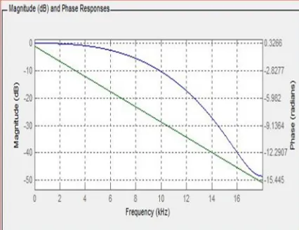
Fig.3 Magnitude [dB] and Phase [rad]of Nuttall Window Technique
PARAMETER VALUES
Sampling Frequency(Fs) 36000Hz
Cut off Frequency(Fc) 8200Hz
[image:5.612.196.415.569.703.2]Technology (IJRASET)
Fig. 4 Filter coefficient on Nuttall Window Technique
Fig. 1 shows the magnitude response of Nuttall window and Fig. 2 shows phase response of Nuttall window. The magnitude response contains ripples in stop band and good pass band response.
[image:6.612.197.415.239.337.2]Fig.5 Magnitude Response of Parzen Window Technique
Fig.6 Phase Response of Parzen Window Technique
[image:6.612.197.417.368.503.2] [image:6.612.198.411.533.697.2]Technology (IJRASET)
Fig.8 Filter coefficients of Parzen Window Technique
Magnitude and phase response of Parzen window is shown in Fig. 5 and 6. In this method magnitude response contains negligible ripples in stop band and it is also having good pass band response.
V. COMPARATIVE
ANALYSIS:-Fig.9 Magnitude and Frequency plot of Nuttall Window
Fig.10 Magnitude and Frequency plot of Parzen Window
VI. RESULT
Window Technique
Mainlobe width
(-3dB)
Relative Sidelobe attenuation
Nuttall 0.125 -88.3dB
Parzen 0.11719 -53dB
Technology (IJRASET)
Frequency
(in kHz)
Magnitude (in dB)
Nuttall window Parzen
window
1 -0.87204 -0.87820
2 -1.76407 -1.76024
3 -2.68446 -2.69213
4 -3.53774 -3.51089
5 -4.36801 -4.43127
6 -5.28072 -5.26538
7 -6.14551 -6.18577
8 -6.99495 -7.04480
Table:(5)-Magnitude & Frequency Result in Nuttall & Parzen Window
VII. CONCLUSION
From this research paper the low pass FIR filter has been designed like Nuttall and Parzen window techniques. The differential analysis of magnitude of filter has been performed the same frequency.
REFERENCES
[1] S Salivahanan, C Gnanapriya, A Vallavaraj, “Digital signal processing” Tata McGraw-Hill, 2nd Edition, pp.3, 443-448.
[2] Keshab.K.Parhi, “VLSI Digital Signal Processing Systems Design and Implementation”. First edition, A Wiley-Interscience Publication, pp. 10-50, 1999.\ [3] Emmanuel C. Ifeacher, Barrie W.Jervis, “Digital Signal Processing”, Second Edition, Pearson Publication, pp. 02-40, 2004
[4] NUTTALL, Albert H. “Some windows with very Good Side lobe Behavior.” IEEE Transactions on Acoustic, Speech and Signal Processing, pp.01-03, February 1981.
[5] G. Rama Marthy, “Finite Impulse Response FIR filter Model of Synapses: Associated Neural Network”, Proceeding of the Fourth Annual IEEE International Confidences on Natural Computation, pp. 3304-3309, 2008.
AUTHORS
Bharat Lal Sahu pursuing bachelor of engineering in electrical & electronics engineering in 4th semester, from Institute of Technology Korba, Chhattisgarh Swami Vivekananda Technical University, Durg, Chhattisgarh, India.
Technology (IJRASET)
Dhananjay Kumar Das pursuing bachelor of engineering in electrical & electronics engineering in 4th semester, from Institute of Technology Korba, Chhattisgarh Swami Vivekananda Technical University, Durg, Chhattisgarh, India.
![Fig.3 Magnitude [dB] and Phase [rad]of Nuttall Window Technique](https://thumb-us.123doks.com/thumbv2/123dok_us/8571180.858055/5.612.198.413.167.415/fig-magnitude-db-phase-rad-nuttall-window-technique.webp)