Design and Optimization of Crankpin - A Review
B.N.Parejiya1, D.B.Morabiya2, Amit Solanki31
P.G Student, Mechanical Engg. Dept. C.U. Shah College of Engineering & Technology, Gujarat, India.
2
Asst. Prof. Mechanical Engg. Dept. C.U. Shah College of Engineering & Technology Gujarat India.
3
Asst. Prof. Mechanical Engg. Dept. C.U. Shah College of Engineering & Technology Gujarat, India.
Abstract -The performance of any automobile largely depends on its size and working in dynamic conditions. The design of the crankpin considers the dynamic loading and the optimization can lead to a pin diameter satisfying the requirements of automobile specifications with cost and size effectiveness. The review of existing literature on crankpin design and optimization is presented. Three-dimension models of crankshaft and crankpin forces were created using Pro/ENGINEER software and software ANSYS was used to analyze the stress status on the crankpin. The maximum deformation, maximum stress point and dangerous areas are found by the stress analysis. The materials, manufacturing process, failure analysis, design consideration etc. of the crankpin are reviewed here.
Keywords—crankpin, optimization, dynamic loading, FEA, ANSYS,crankshaft design.
I. INTRODUCTION
Crankshaft of Internal Combustion Engine is a well known phenomenon. The problem of their premature failure has attracted several investigators for over a century. Forces acting on the crankpin are complex in nature. The piston and the connecting rod transmit gas pressure from the cylinder to the crankpin. It also exerts forces on the crankpin, which is time varying.
Crankshaft consists of the parts which revolve in the main bearings, the crankpin to which the big ends of the connecting rod is connected, the crank arms or webs (also called cheeks) which connect the crankpins and the shaft parts. The crankpin is like a build in beam with a distributed load along its length that varies with crank position.
Crankshaft assembly is shown in fig.1.1 To reduce the friction, roller bearing is used between the connecting rod and the pin. The roller bearings have non-conformal contact surfaces (line or point contact called hertzian contacts), which support the moving parts of the crankshaft assembly with rolling action at the interface . An oil film between the interfaces prevents metal-to-metal contact [5].
Fig:-1.1 Assembly of crankshaft
I N T E R N A T IO N A L J O U R N A L F O R R E S E A R C H I N A P P L I E D S C I E N C E AN
D E N G I N E E R I N G T E C H N O L O G Y (I J R A S E T)
Fig:-1.3 Model of crankpin
II. TYPES OF CRANKPIN
1) Cross hole type crank pin
2) Straight hole type crank pin
Fig:-1.4 Cross hole type crank pin
In Cross hole type crankpin have two hole in cross way for lubrication purpose.
In Straight hole type crank pin have two hole in straight way for lubrication purpose.
III. FORCES ON CRANKPIN
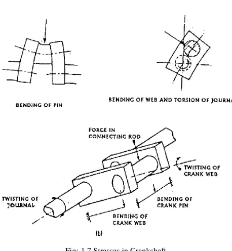
In the process of converting the linear reciprocating motion of the pistons into a rotational output, the crankshaft undergoes both bending and torsion. As these forces are transmitted through the crankshaft, it becomes highly stressed, particularly so at the crankpin/web and the journal/web intersections of the cranked shaft. As a consequence, fillet radii are used in these areas to reduce the stresses, but if the shaft is not carefully designed, these stresses can still reach unacceptably high levels with regard to material strength and fatigue life.
Fig:-1.6 Force acting on crankpin
Radial force, Tangential force, Inertia force STRESSES DUE TO FORCES ON CRANKPIN Bending stress and Shear stress.
IV. STRESSES IN CRANKSHAFT
Since the crankshaft experiences a large number of load cycles during its services life, fatigue performance and durability of this component has to be considered in the design process. In converting the linear motion of the piston into rotational motion, crankshafts operate under high loads and require high strength.
The stresses which arise in a crankshaft are mainly due to bending and torsion. Due to the high dynamic load the crankpin is subjected to bending, each web is subjected to bending and twisting and journal is mainly subjected to twisting.
(3) Due to shrinkage of the web onto the journals, compressive stresses are set up in journals & tensile hoop stresses in the webs.
Fig:-1.7 Stresses in Crankshaft
V. FAILURE OF CRANKSHAFT ASSEMBLY AND CRANKPIN
Reasons for Failure of crankshaft assembly and crankpin
A) Shaft misalignment
B) Vibration cause by bearings application
C) Incorrect geometry(stress concentration)
D) Improper lubrication
E) High engine temperature
F) Overloading
G) Crankpin material & its chemical composition
H) Pressure acting on piston
Fatigue spalling initiates in the depth of material by subsurface stress field close to the contacting surface . It then grows to the surface in the form of micro-spall or crack .When these localized inelastic subsurface deformations such a cracks interact, the material break up, disrupt the oil film in the region of highest load and lowest oil film thickness .
[image:4.612.317.561.210.346.2]Surface defects like burr, surface mark, pit mark, dents have observed on crankpin. shows damage marks on crankpin surface which acts as a stress concentration location. Similarly burr and deep machine tool mark near oil hole . This can act as a stress raiser during rolling contact phenomenon [5].
Fig:-1.8 crankpin spalling
These observation suggests that external contaminants like hard particles, wear debris, and flakes that might have entered into the sliding zone. The hard particles abrasive contaminants cause indentation or cutting wear damage to the softer material. The average depth of the cavities measured at the contact
surfaces was about 25 µm. It is nearly impossible to observe
these kinds of failures during the engine running condition.
Fig 1.9 Surface damage on the crankpin
VI. MATERIALS AND MANUFACTURING PROCESSES
Crankpin meet the demands for high performance engines, lightweight design, component reliability and low through cost manufacturing.
The crankpin are subjected to shock and fatigue loads. Thus material of the crankpin should be tough and fatigue resistant. The crankpin are generally made of carbon steel, forged steel and alloy steel. It also improve the strength of component.
[image:4.612.313.555.470.564.2]I N T E R N A T IO N A L J O U R N A L F O R R E S E A R C H I N A P P L I E D S C I E N C E AN
D E N G I N E E R I N G T E C H N O L O G Y (I J R A S E T)
Induction hardening is generally carried out to make outer surface of steel component hard and to increase wear resistance of material without loosing its original toughness and ductility
of the material. It’s main application is in manufacturing of automobile components viz. Crank Pin, gears crank shaft, crank pins, axles etc.
VII. FAILURE ANAYLSIS OF CRANKSHAFT
Osman Asi [9] performed failure analysis of a diesel engine crankshaft used in a truck, which is made from ductile cast iron. The crankshaft was found to break into two pieces at the crankpin portion before completion of warranty period. The crankshaft was induction hardened. An evaluation of the failed crankshaft was undertaken to assess its integrity that included a visual examination, photo documentation, chemical analysis, micro-hardness measurement, tensile testing, and metallographic examination. The failure zones were examined with the help of a scanning electron microscope equipped with EDX facility. Results indicate that fatigue is the dominant mechanism of failure of the crankshaft.
Another crack detection method is a modified version of the gel electrode technique. This technique could identify both the primary fatigue cracks and a distribution of secondary sites of less severe fatigue damage. The most useful aspect of this study is that the ELPO film can be applied before or after the fatigue test, and in both cases, the gel electrode technique is successful at detecting fatigue damage.. As can be seen, a fatigue crack of length 2.2 cm exists along the edge of the fillet, which the markings from this technique clearly identify.
VIII. DESIGN CONSIDERATIONS
Jaimin Brahmbhatt, Prof. Abhishek choubey [4].Crankshaft is one of the critical components for the effective and precise working of the internal combustion engine. In this paper a dynamic simulation is conducted on a crankshaft from a single cylinder 4- stroke diesel engine. A three-dimension model of diesel engine crankshaft is created using SOLID WORKS software. Finite element analysis (FEA) is performed to obtain the variation of stress magnitude at critical locations of crankshaft. Simulation inputs are taken from the engine specification chart. The dynamic analysis is done using FEA Software ANSYS which resulted in the load spectrum applied to crank pin bearing. This load is applied to the FE model in ANSYS, and boundary conditions are applied according to the engine mounting conditions. The analysis is done for finding critical location in crankshaft. Stress variation over the engine cycle and the effect of torsion and bending load in the analysis
theoretically and FEA software ANSYS. The relationship between the frequency and the vibration modal is explained by the modal and harmonic analysis of crankshaft using FEA software ANSYS.
The Value of Von-Misses Stresses that comes out from the analysis is far less than material yield stress so our design is safe and we should go for optimization to reduce the material and cost.
After Performing Static Analysis Performed Dynamic analysis of the crankshaft which results shows more realistic whereas static analysis provides an overestimate results. Accurate stresses and deformation are critical input to fatigue analysis and optimization of the crankshaft. So we can Say that Dynamic FEA is a good tool to reduce Costly experimental work.
IX. DYNAMIC LOAD ANALYSIS
Dr. K.H. Jatkar, Mr. Sunil S. Dhanwe [3] In this study a dynamic analysis of single cylinder petrol engine was conducted. Finite element analysis was performed to obtain the variation of the stress magnitude at critical locations of connecting rod and crankshaft. The dynamic analysis resulted in the development of the load on piston. This load is calculated from MATLAB. This load was then applied to the FE model and boundary conditions were applied according to the engine assembly. It is observed that maximum stress is developed at crank pin of crank shaft. The maximum stresses are developed at the fillet section of the big and the small end of connecting rod. Hence, the project deals with the stress analysis of connecting rod and crankshaft by Finite Element Method using ANSYS WORKBENCH 11.0 Software. Also Results obtained from the analysis were then compared with analytical method.
The performance of any automobile largely depends on its size and working in dynamic conditions. The design of the crankshaft considers the dynamic loading and the optimization can lead to a shaft diameter satisfying the requirements of automobile specifications with cost and size effectiveness. The review of existing literature on crankshaft design and optimization is presented. The materials, manufacturing process, failure analysis, design consideration etc. of the crankshaft are reviewed here.
X. COMPUTER AIDED ANAYLSIS OF CRANKSHAFT
Development of an engine crankshaft in a framework of computer-aided innovation by A. Albers et al.[7] describes the conceptual framework of a general strategy for developing an engine crankshaft based on computer-aided innovation, together with an introduction to the methodologies from which our strategy evolves. It begins with a description of two already popular disciplines, which have their roots in computer science and natural evolution: evolutionary design (ED) and genetic algorithms (GAs). A description of some optimization processes in the field of mechanical design is also presented. The main premise is the possibility to optimize the imbalance of a crankshaft using tools developed in this methodology. This study brings together techniques that have their origins in the fields of optimization and new tools for innovation.
A review of Crankshaft Lightweight Design and Evaluation based on Simulation Technology is presented by Sheng Su, et al .[10] In order to reduce fuel consumption and emission and improve efficiency, it is essential to take lightweight design into consideration in concept design phase and layout design phase. Crankshaft is one of the most important components in gasoline engine, and it is related to durability, torsional vibration, bearing design and friction loss, therefore lightweight crankshaft must meet the needs to see to it that the final design is satisfactory.
XI. COST REDUCTION
The automotive crankshaft, one of the more metal intensive components in the engine, provides an attractive opportunity for the use of alternate materials and processing routes. A systematic cost estimation of crankshafts is provided in the work of Nallicheri et al. [11]. Dividing the cost of crankshafts into variable and fixed cost, they evaluate and compare the production cost of crankshafts made of nodular cast iron, austempered ductile iron, forged steel, and micro alloyed forged steel. The common variable cost elements are named as the costs of material, direct labor, and energy. The common elements of fixed cost are named as the costs of main machine, auxiliary equipment, tooling, building, overhead labor, and maintenance.
A study was performed to examine the cost reduction opportunities to offset the penalties associated with forged steel, with raw material and mach inability being the primary factors evaluated by Hoffmann et al.[8] Materials evaluated in their study included medium carbon steel SAE 1050 (CS), and medium carbon alloy steel SAE 4140 (AS); these same grades at a sulfur level of 0.10%, (CS-HS and AS-HS); and two micro-alloy grades (MA1 and MA2). The micro-micro-alloy grades
evaluated offered cost reduction opportunities over the original design materials. The micro-alloy grade could reduce the finished cost by 11% to 19% compared to a quenched and tempered alloy steel.
XII. OPTIMIZATION
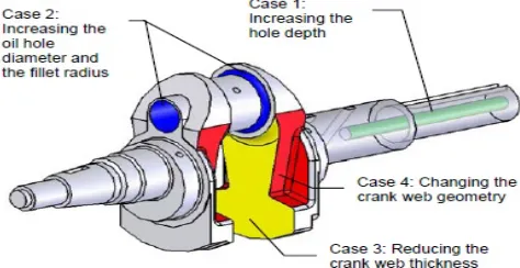
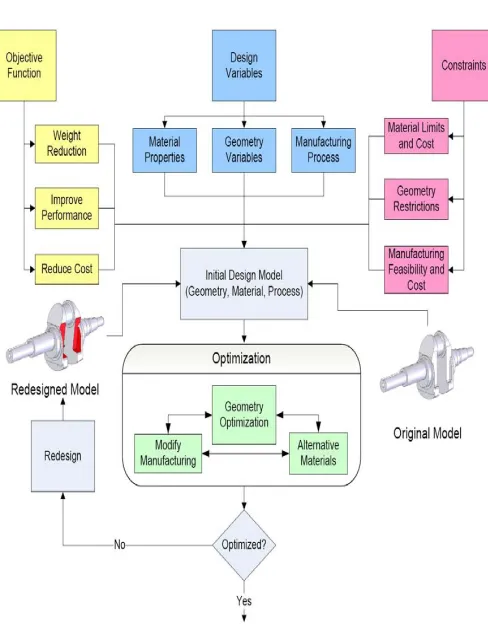
[image:6.612.319.556.490.612.2]Farzin H. Montazersadgh, Ali Fatemi [6] In this study a dynamic simulation was conducted on a forged steel crankshaft from a single cylinder four stroke engine. Finite element analysis was performed to obtain the variation of the stress magnitude at critical locations. The dynamic analysis resulted in the development of the load spectrum applied to the crankpin bearing. This load was then applied to the FE model and boundary conditions were applied according to the engine mounting conditions. Results obtained from the aforementioned analysis were then used in optimization of the forged steel crankshaft. Geometry, material, and manufacturing processes were optimized using different geometric constraints, manufacturing feasibility, and cost. The first step in the optimization process was weight reduction of the component considering dynamic loading. This required the stress range under dynamic loading not to exceed the magnitude of the stress range in the original crankshaft. Possible weight reduction options and their combinations were considered. The optimization and weight reduction were considered in an interactive manner and evaluated by manufacturing feasibility and cost. The optimization process resulted in an 18% weight reduction, increased fatigue strength, and a reduced cost of the crankshaft.
I N T E R N A T IO N A L J O U R N A L F O R R E S E A R C H I N A P P L I E D S C I E N C E AN
D E N G I N E E R I N G T E C H N O L O G Y (I J R A S E T)
Fig 1.11 General flow chart of forged steel crankshaft optimization procedure
Fig 1.12 Stress distribution under critical loading condition at the crank angle of 5 degrees after TDC.
An optimization study was performed on a forged steel crankshaft that considered the geometry, performance, manufacturing process, and cost. A major constraint of this optimization was for the optimized crankshaft to replace the
geometry included local changes at different locations on the crankshaft, which were then combined to obtain the final optimized geometry.
CONCLUSIONS
1) In the crankshaft, the crack grows faster on the free surface while the central part of the crack front becomes straighter.
2) Fatigue is the dominant mechanism of failure of the crankshaft.
3) Comparative study needs to be applied for the selection of material and manufacturing process so as to have cost effectiveness and shape with fewer defects respectively.
4) Static analysis provides over estimated results. Accurate stresses are input to optimization of the crankpin.
5) There are two different load sources in an engine; inertia and combustion. These two load source cause both bending and torsional load on the crankshaft. The maximum load occurs at the crank is at dead centre. At this, only bending load is applied to the crankshaft. 6) Accurate stresses are critical input to fatigue analysis
and optimization of the crankpin.
7) Design developments have always been an important issue in the crankpin production industry, in order to manufacture a less expensive component with the minimum weight possible and proper fatigue strength and other functional requirements. These improvements result in lighter and smaller engines with better fuel efficiency and higher power output. 8) The maximum deformation appears at the center of
crankpin neck surface.
9) Analysis Results. So we can Say that Dynamic FEA is a good tool to reduce Costly experimental work.
REFERENCES
[1] S.M.Sorte, S.M.Sheikh: Stress Analysis and Design Optimization Of Crankpin. International Journal of Science and Modern Engineering (IJISME) ISSN: 2319-6386, Volume-1, Issue-4, March 2013
[2] Amit Solanki, Ketan Tamboli, M.J.Zinjuwadia, “Crankshaft Design and Optimization- A Review”. National Conference on Recent Trends in Engineering & Technology 13-14 May 2011
[3] Dr. K.H. Jatkar, Mr. Sunil S. Dhanwe : Dynamic Analysis of Single Cylinder Petrol Engine. Applications (IJERA) ISSN: 2248-9622 Vol. 3, Issue 3, May-Jun 2013, pp.1177-1183
[image:7.612.41.286.464.614.2][6] Farzin H. Montazersadgh, Ali Fatemi : Optimization of a Forged Steel Crankshaft Subject to Dynamic Loading. SAE Technical Paper No. 2007-01-0258, Society of Automotive Engineers, Warrendale, PA, USA.
[7] A. Albers, N. Leon-Rovira, H. Aguayo, T. Maier“Development of an engine crankshaft in a framework of computer-aided innovation“.Institute of Product Development (IPEK), Universita¨t Karlsruhe (TH), Center for Innovation in Design & Technology (CIDT), ITESM, Monterrey Campus, Mexico, SAE Technical Paper No. (2009) 604–612.
[8] Hoffmann, J. H. and Turonek, R. J., 1992, “High Performance Forged Steel Crankshafts - Cost Reduction Opportunities,” SAE Technical Paper No.
920784, Society of Automotive Engineers, Warrendale, PA,USA. 0258, Society of Automotive Engineers, Warrendale, PA, USA.
[9] Osman Asi ,”Failure analysis of a crankshaft made from ductile cast
iron”,Department of Mechanical Engineering, Usak Engineering Faculty, Afyon
Kocatepe University, 64300 Usak, Turkey,Received 3 November 2005; accepted 3 November 2005.Available online 7 February 2006,13 (2006) 1260– 1267
[10] Sheng Su, Fuquan Zhao, Yi You, Huijun Li, Jingyan Hu, Feng-kai Wu,
“Crankshaft Lightweight Design and Evaluation Based on Simulation Technology” Chen Yang Zhejiang Geely Automobile Institute CO. LT.
[11] Nallicheri, N. V., Clark, J. P., and Field, F. R., 1991, “Material Alternatives for the Automotive Crankshaft; A CompetitiveAssessment Based
on Manufacturing Economics,” SAE Technical Paper No. 910139, Society of