224
RESEARCH AND APPLICATION THE MEASURING AND
CONTROLLING INSTRUMENT OF MOUNTAIN
GREENHOUSES
1
MA JIWEI, 2LUN CUIFEN, 3LIN ZHIPENG, 4ZHUANG CHENG, 5LU WEINA, 6LIN
HONGJU
1 Assoc. Prof.,1-6 theCollege of Mechanical and Electrical Engineering, Hebei Normal University of Science
and Technology, Qinhuangdao China
Email:[email protected]
ABSTRACT
This system uses a new single-chip computer extends MAX485 serial communication module and wireless transceiver chip nRF905. According to the scale of greenhouse and wiring, the instrument communication mode can flexibly set -- a wired or wireless communication. The PC communication interface design enables PC to communicate with the network relay node and manage the system by wired communications and also by wireless communications. This system has been successfully applied to parameters measurement and control of our experimental base and the surrounding greenhouses.The results showed that the system is facilitate to expand, it has flexible network, low construction cost, which laid foundation for the modernization management of large agricultural facilities.
Keywords: Mountain Greenhouses, Environmental Parameter, Local Area Network, Means Of Communication
1. INTRODUCTION
China is a large agricultural country, the mountainous area is big and it is widely distributed. Due to the development of the modern greenhouse agriculture in mountainous areas, automated environmental monitoring system is in urgent need. Traditional monitoring methods lead to low measuring precision, control untimely, large workload and work intensity, poor system reliability, which results in low levels of modern management of agricultural production, low quality of agricultural products. In recent years, there have been successful examples of application of computer remote monitoring in agricultural production both at home and abroad, Especially, the rapid development of networking technology and applications has made modern agriculture obtain considerable development. But these introduced modern facilities have problems of high price, high running costs and so on, they can only be applied to the management of science and technology demonstration area, farmers can’t afford them. Especially in mountain greenhouse, the distribution is scattered and the size is small, they are difficult to promote[1]. To further resolve the problem in measurement and control of agricultural facilities
group, achieve the localization process of measurement and control of the facility, the smallest measurement and control system which takes new single chip computer with high speed as the core is further developed on the basis of successful experience of the research group, this system has both wired and wireless communication function. This portable single-version instrument can be
applied to small single shed greenhouse
independently. At the same time, the detecting and controlling instrument can also be used as the measurement and control terminal or relay nodes to realize the flexible networking in wire or wireless form. PC is responsible for the centralized management of large greenhouse system, the automation degree of management is improved for different scale of agricultural facilities.
2. HARDWARE DESIGN OF THE
MEASURING AND CONTROLLING SYSTEM OF LARGE GREEN HOUSE
set the communication means of corresponding primary measurement and control instrument according to user's actual need and facilities cabling.
2.1 System Composition And Network Structure
Local measurement and control networks of greenhouse environment parameters can takes communication means combined of wired and wireless means, that is: it consists of several master instrument nodes connected to RS485 bus and several slave instrument nodes placed around the master instrument nodes within a certain range, the master and slave instrument are connected via wireless communication, this constitutes a star topology structure in which the master instrument is as the core. The second proposal of network composition can also be used, that is: by using serial port RS232 and conversion interface nRF905, the PC host communicates with the master instrument in a wireless way, the star network topology structure is still adopted to realize the wireless communication between the master and the slave instrument[3]. The environment information processing system of greenhouse is established to realize data upload and historical storage, data printing, historical data queries, issuing control commands and so on, management of measurement and control system in large greenhouse is realized.
2.2 Hardware Design Of Measurement And Control Instrument And Working Principle
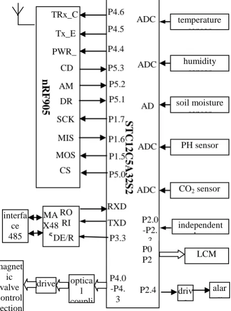
The detecting and controlling instrument is made up of CPU module, LCM monitor, sensors, communication module, as well as non-contact control information output modules. This system takes high speed, low power consumption, strong anti-jamming of new type single chip computer STC12C5A32S2 as the core, which keeps the system to the minimum, achieves benefits of a large quantity of information storage, information transmission and testing. It has both wired and wireless communication capabilities. Hardware structure diagram is as shown in Figure 1.
STC12C5A32S2 has dual-serial, SPI serial port, 8-channel 10-bit high-speed a/d converters, E2PROM of 28KB, 1280B on-chip SRAM and 44-bit I/O port and online programming features. Compared to other 16-bit high-performance MCU, DSP system, it has advantage of low power consumption, small size and high reliability, which is the first choice of intelligent instrument design.
The instrument takes the portable structure, according to the testing parameter requirements; it can connect different sensors, make real-time
collection of temperature, humidity, soil moisture, carbon dioxide content and other environmental parameters in the greenhouse. Place one instrument in one greenhouse, users can use the function keys on the table to enter the features setting interface, set the minimum and maximum values for different parameters. The instrument compares the acquisition parameter value with the set value, displays the collection data and parameter out-of-limit on large-screen LCM. The instrument
makes overall evaluation of greenhouse
environment, controls factors such as heating, spray, ventilation devices, and simultaneously sends out sound signals of parameters out-of-limit. The slave instrument packages data, such as the meter number, gathered data and communication matching address, transmit to the wireless transmitter, the wireless transmitter launches the data to the corresponding master instrument; The master instrument transfers data collected from itself and uploaded by all the slave instrument around it to the monitoring center by wired (or wireless) means. PC sets the communication mode of wired or wireless communication depending on whether the master instrument is attached to the RS485 bus; Parameter settings for each instrument, the start-stop control of
humidity sensor
PH sensor
CO2 sensor
[image:2.612.314.543.410.719.2]ADC ADC ADC ADC soil moisture sensor AD LCM optica l coupli drive magnet ic valve control section independent k P2.0 -P2. 3 driv e alar m SCK MIS MOS CS P1.7 P1.6 P4.0 -P4. 3 P1.5 P5.0 P3.3 P0 P2
226 the corresponding devices can also be controlled and set by PC downloading commands or data.
2.3 THE BASIC OPERATING PRINCIPLE AND CONNECTION METHODS OF TRANSCEIVER Nrf905
nRF905 adopts VLSI ShockBurst technology of Company Nordic, it is a real single chip, low-power wireless transceiver working on 433/868/915MHz ISM band. ShockBurst TX work mode can automatically generate a preamble and CRC code, can easily be programmed and configured via SPI interface, which shorten the software development time. It can be very easy to implement energy-saving in power-down modes, its operating frequency is stable and reliable, it is the ideal choice for low-power and wireless transmission. Communication interface has been used to extend wireless transceiver module nRF905. The wireless communication distance this system designs is 200m, the field test results are very reliable.
This system uses serial port to extend MAX485. Design of communication module with both wired and wireless data transceiver function solves the problem that the master measurement and control instrument not only makes wireless transceiver with the measurement instrument, but also makes wired communication with PC, the communication modes can be flexibly set which make the instrument more flexible.
2.4 Design Of Communication Interface Between Pc And Master Instrument Node
PC for monitoring has only serial port RS-232, so this system designed serial port by using two serial ports and SPI interface of STC12C5A32S2. The serial port of single-chip computer is connected to the interface RS-232 of PC; the same as the communication module of master instrument, serial port 2 is connected to MAX-485, PC for monitoring is connected to RS-485 bus, by this simple master-slave bus structure, only 2 communication lines are needed to achieve wired communication between PC and the master instrument node. SPI interface of single-chip computer is connected to SPI interface of wireless transceiver module nRF905, distributed control system for a point-to-multipoint wireless communication is realized.
3. DESIGM OF SYSTEM SOFTWARE
System software is made up of running programs (including communications subprograms) of the measurement and control instrument and PC running programs.
3.1 Design Of Programs For Measurement And Control Instrument
The application program for the measurement and control instrument is composed by the main program, subroutine of data acquisition (including alarm), display subprogram, keyboard scan interrupt routines, PID adjusting as well as data transceiver subroutine.
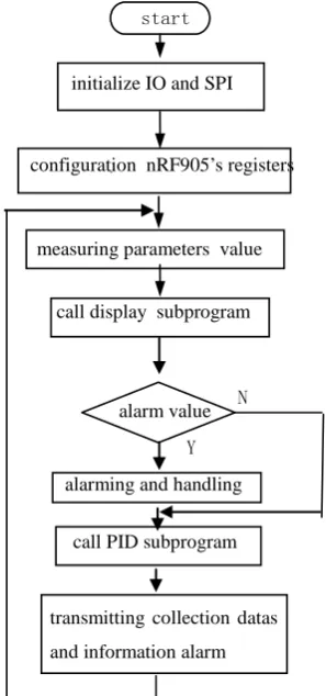
The main program is for system initialization, the master key, A/D enabling setting, SPI command words writing, nRF905 configuration register writing. In order to improve the accuracy of test
data, for each measured parameter, read A/D converted data 100 times in a row, calculate the average value as the collection result each time. The main program tests and shows the various parameter circularly, analyzes data according to the set value, calls the PID control program to control the output, alarms when the parameter is out of limit, starts nRF905 to send the collection data and alarm message. The software process is as shown in Figure 2. System software of the master instrument
、 start
initialize IO and SPI
measuring parameters value configuration nRF905’s registers
call display subprogram
alarm value
call PID subprogram
transmitting collection datas
and information alarm alarming and handling
[image:3.612.339.488.269.587.2]Y N
should add function of wireless transceiver with the measurement instrument and wired (or wireless) communication with the monitoring center.
3.2 Design Of Transceiver Subprogram
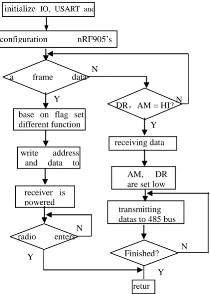
For system wireless communication, a complete package includes: preamble, communication address, number of slave instrument, collection data (temperature, humidity, CO2 concentrations, soil moisture, etc) the CRC check code. nRF905 automatically adds the preamble and CRC check code; length of communication address is 4 bytes, only when the addresses of both sides of the communication match on, can communicate carries on, which ensures the reliability of communication; number length of the slave instrument is 1 byte, which is for judging data sources; The parameter data is defined as a 4-byte float type, a total of 16 bytes.
After collecting real-time data of several parameters, nRF905 determines whether they are out of limit one by one, if one of them is out of limit, alarm is issued. At the same time, pins TRX_CE and TX_EN are set to high, nRF905 ShockBurst TX is started. By single-chip computer, the data to be transmitted are packaged and sent to nRF905. nRF905 adds preamble and CRC codes to the data, then a complete frame of data is formed for wireless transmitter. After transmitting, pin DR is set to high. Corresponding master instruments test air information, when nRF905 receives valid address, AM is set to high, nRF905 unpacks data automatically, pin DR is set to high. When the master instrument has test pin DR is high, pin TRX_CE is reset, then nRF905 enters idle mode, single-chip computer reads the received data from nRF905 by SPI interface, transmits them to PC by serial RS485 bus(or wireless communication). Subprogram of wireless communication transceiver is as shown in Figure 3.
3.3 Feature Of Pc Management Software
PC is responsible for receiving, displaying, storing the parameters values uploaded by each measurement and control instrument. It has function of displaying the greenhouse number, showing measured parameters, data reports, graphics generation, data storage, report printing. PC is as the master for setting communication mode of the master measurement and control instrument, initiating communication; more on-site monitoring instruments are as the slave machines, and they must wait for allowing signals from the host before data transmission. PC sends and receives information from the communication chain from the slave machine at regular time, the slave machine
will always be in a passive state, and ready all the times to respond to communication requests from the hosts. Users access to real-time data interface of the management system, view real-time data in different greenhouse for all networking according to the tree diagram of greenhouse management that system generated systems, know the setting of parameters in different greenhouse and real-time parameter changes, and generates data reports periodically.
4. FIELD SIMULATION TEST RESULTS
AND ANALYSIS
The test system consists of a PC, 2 master
measurement and control instruments, 6 slave instruments placed in 8 green houses for field test. The test results showed that the technical performance such as the designed 1000m wired
communication distance, 150m wireless
communications distance (no obstacles), response time <15s are fully realized.
This measurement and control instrument with both wired and wireless communication module further reduced the cost for the setting up of
initialize IO, USART and
configuration nRF905’s
Y
N a frame data
base on flag set different function
write address and data to
receiver is powered
radio enters
DR,AM = HI?
receiving data
AM, DR are set low
transmitting datas to 485 bus
Finished? Y
N
N
N
Y
Figure 3 Subprogram Flow Chart Communication Of Master Y
[image:4.612.316.530.269.569.2]228
greenhouse group control system, it is especially suited for the setting up of mountain greenhouse measurement and control system.
①select wired or wireless communication
according to the actual need when setting up the greenhouse measurement and control system. For example, wired communication is used in places easy to lay lines or in relatively fixed greenhouse, while wireless communication is used in places difficult to lay lines or in less fixed greenhouse, which shorten the early construction period, reduced system investment, made the later upgrading easy. Development and promotion of this practical greenhouse group control system with flexible networking and low cost is speeded up.
②Carrier detection of NRF905, address matching, and automatic retransmission technology is the important guarantee for effectively receiving data, which savd software development time and also allows wireless communication system with high reliability. By use of electrical isolation control technologies, digital filtering, communication anti-collision, CRC check technology and so on, problem of stability and reliability in single-chip computer monitoring system is solved.
③Detection parameters is not very strict for time, in the designed sampling cycle, the time is redundant, the selected quick micro-controller further guarantees the stability and reliability of the system.
REFERENCES:
[1] Du Shangfeng, Li Yingxia, Ma Chengwei, “Current situation on greenhouse environment control system modes in China”, Transactions of the Chinese Society of Agricultural Engineering, 2004, vol 20, no 1,pp.7-12.
[2] Qi Wenxin, Zhou Xuewen, ” Design and application of distributed intelligent greenhouse computerized control system”, Transactions of the Chinese Society of Agricultural Engineering, 2004, vol 20, no 1,pp.246-249.
[3] Liu Shiguang, Liu Jianmin, Ma Jiwei1, ” Design of Long-distance Measuring-controlling System Based on Topological Structure for Agricultural Facilities”, Transactions of the Chinese
Society for Agricultural Machinery, 2006, vol 37, no 1,pp.101-103,117.