PARIS RESEARCH LABORATORY
d i g i t a l
July 1991 G ´erard Berry
A Hardware Implementation
of Pure Esterel
G ´erard Berry
Author’s address:
G´erard Berry Ecole des Mines Sophia-Antipolis 06565 Valbonne, France
e-mail: [email protected], [email protected]
Paper presented at the 1991 International Workshop on Formal Methods in VLSI Design, Miami, Florida, January 1991.
c
Digital Equipment Corporation 1991
Esterel is a synchronous concurrent programming language dedicated to reactive systems (controllers, protocols, man-machine interfaces, etc.). Esterel has an efficient standard software implementation based on well-defined mathematical semantics. We present a new hardware implementation of the pure synchronization subset of the language. Each program generates a specific circuit that responds to any input in one clock cycle. When the source program satisfies some statically checkable dynamic properties, the circuit is shown to be semantically equivalent to the source program. The hardware translation has been effectively implemented on the programmable active memory Perle developed by J. Vuillemin and his group at Digital Equipment Paris Research Laboratory.
R ´esum ´e
Circuits, logic synthesis, synchronous programming, Esterel.
Acknowledgements
2 Pure Esterel 3 2.1 Signals and Events
: : : : : : : : : : : : : : : : : : : : : : : : : : : :
3 2.2 Modules: : : : : : : : : : : : : : : : : : : : : : : : : : : : : : : : : :
4 2.3 Kernel Statements: : : : : : : : : : : : : : : : : : : : : : : : : : : : :
4 2.4 The Intuitive Semantics: : : : : : : : : : : : : : : : : : : : : : : : : :
5 2.5 Examples: : : : : : : : : : : : : : : : : : : : : : : : : : : : : : : : : :
7 2.6 Full Esterel: : : : : : : : : : : : : : : : : : : : : : : : : : : : : : : : :
83 The Behavioral Semantics 10
3.1 Form of the Rules
: : : : : : : : : : : : : : : : : : : : : : : : : : : : :
10 3.2 Inductive Rules: : : : : : : : : : : : : : : : : : : : : : : : : : : : : :
11 3.3 Correct Programs: : : : : : : : : : : : : : : : : : : : : : : : : : : : :
144 The Haltset Coding of States 15
4.1 Haltsets
: : : : : : : : : : : : : : : : : : : : : : : : : : : : : : : : : : :
16 4.2 Recovering derivative from haltsets: : : : : : : : : : : : : : : : : : :
185 Principle of the Hardware Implementation 20 5.1 A First Example
: : : : : : : : : : : : : : : : : : : : : : : : : : : : : :
21 5.2 Translating Parallel and Exceptions: : : : : : : : : : : : : : : : : : :
24 5.3 Summary of the Translation: : : : : : : : : : : : : : : : : : : : : : : :
27 5.4 Optimization: : : : : : : : : : : : : : : : : : : : : : : : : : : : : : : :
28 5.5 The Translation is Sometimes Incorrect: : : : : : : : : : : : : : : : :
286 The Formal Translation to Hardware 29
6.1 Circuits
: : : : : : : : : : : : : : : : : : : : : : : : : : : : : : : : : : :
29 6.2 The Translation Environment: : : : : : : : : : : : : : : : : : : : : : :
30 6.3 The Translation Rules: : : : : : : : : : : : : : : : : : : : : : : : : : :
317 Correctness of the translation 33
8 Implementation 36
8.1 Actual Implementation on Perle0
: : : : : : : : : : : : : : : : : : : : :
36 8.2 Simulation and Correctness Proofs: : : : : : : : : : : : : : : : : : :
379 Conclusion 37
1 Introduction
Esterel
[3, 4, 5, 10] is a synchronous programming language devoted to reactive systems, that is to systems that maintain a continuous interaction with their environment by handling hardware or software events. Its software implementation is currently used in industry and education to program software objects such as real-time controllers, communication protocols [6, 23], man-machine interfaces [14], systems drivers, etc. In this paper, we present a hardware implementation of the pure synchronization subset of the language that builds a specific circuit for each program. We prove the correctness of this implementation with respect to the mathematical semantics of the language under some conditions to be satisfied by the source program. We describe the experiments made so far and the possible uses of the hardware implementation.The Perfect Synchrony Hypothesis
Esterel
is an imperative concurrent language with very high-level control and event manipulation constructs. It is based on a perfect synchrony hypothesis [2], which states that control transmission, communication, and elementary computation actions take no time, or, in other words, that the program is conceptually executed on an infinitely fast machine. The control structures include sequencing, testing, looping, concurrency, and a powerful exception mechanism which is fully compatible with concurrency, unlike in asynchronous concurrent programming languages [1]. The primitive communication device between concurrent statements is instantaneous broadcasting of signals.The perfect synchrony hypothesis is shared by the synchronous data-flow languages
Lustre
[12, 20] andSignal
[17, 19]. It makes programming very modular and flexible, and it makes it possible to reconcile input-output determinism and concurrency. This is a great benefit over classical asynchronous languages such asOccam
orAda
that are inherently non-deterministic, a characteristic that makes reactive programming and debugging needlessly difficult, as explained in [1].Esterel
is rigorously defined by well-analyzed mathematical semantics, given in both denotational and operational styles [5, 18].Esterel in Software
Esterel in Hardware
Since many CAD systems directly support automata-like specifications,
Esterel
programs can be implemented in hardware by first translating them into automata using the standard compiler. However, this indirect translation looses most of the source concurrent structure. This is usually a good idea in software, where run-time concurrency is in fact expensive, but not in hardware, where concurrency is free and should be used as much as possible. Furthermore, there is no simple relation between the source program size and the size of the generated automaton. In the worst case, the automaton size can be exponential in the source program size, and square factors are not rare. Again, this is much more acceptable in software than in hardware.The direct hardware implementation we present here is conceptually much better; it is based on on Gonthier’s semantic analysis of
Esterel
[18]. It transforms each program into a digital circuit that exactly reflects the source concurrency and communication structure. The circuit computes the response to any input within exactly one clock cycle, however complex the program is. The translation is purely structural (compositional) and linear in size. However, it is at present limited to the pure synchronization subset of the language, which we callPure
Esterel
, and it works only under some restrictive conditions to be satisfied by the source program.The translation is completely formalized and proved correct with respect to the mathematical semantics under the above restrictive conditions. Correctness relies on the fact that perfect synchrony does not depart very much from digital circuit synchrony: zero-time is simply replaced by one cycle.
Actual Implementation and Applications
The translation from programs to circuits has been implemented within the existing
Esterel
compiler. We have run very successful experiments using theXilinx
TM
-basedPerle0
programmable coprocessor developed at DEC Paris Research Laboratory by J. Vuillemin et.al. [8, 25].
We are currently investigating two kinds of applications:
Implementing existing
Esterel
programs in hardware to match high performanceconstraints. For example, we have directly implemented the kernel of a fast local area network protocol that was developed in Esterel at INRIA [22].
Programming hardware controllers in
Esterel
. The language turns out to bewell-adapted to programming the control part of a circuit, which is known to be difficult and error-prone with usual techniques. We show a toy example in Appendix A.
verify the programs; one can experiment various trade-offs between hardware and software without changing the source code.
Esterel and Lustre
The
Lustre
synchronous language has also been implemented on hardware at DEC PRL, and the implementations ofEsterel
andLustre
are fully compatible1. It has to be noted that both languages differ from most existing hardware description languages by the fact that they deal only with behaviors and not with hardware objects, and also by the care with which they were mathematically defined and studied. To describe circuits,Lustre
andEsterel
are complementary:Lustre
is well-adapted to data path description,Esterel
is well adapted to control automata.Structure of the Paper
Section 2 presents the pure
Esterel
language and its intuitive semantics. We give enough material for the paper to be self-contained, but not to fully understand theEsterel
programming style, referring to [4, 5] and to theEsterel
documentation for these aspects. The mathematical semantics ofPure Esterel
is given in Section 3. Section 4 presents an essential part of the theory ofEsterel
, the coding of states by haltsets. This coding is the root of the hardware translation, whose principle is presented by examples in Section 5. The translation is then formalized in Section 6 and proved correct in Section 7. We discuss the actual implementation onPerle0
in Section 8 and conclude. An appendix gives the example of a simple bus interface and briefly analyzes the adequacy ofEsterel
to program hardware controllers.2 Pure Esterel
We first present signal and events which are the basic objects manipulated by
Pure
Esterel
programs. We then present the kernel language on which the semantics is defined and the full language that includes kernel-definable user-friendly statements.2.1 Signals and Events
Pure Esterel
deals with signals S;
S1;
. . . and with eventsE;E
1;
. . . that are sets ofsimultaneous signals. A signal that belongs to an event is said to be present in that event, otherwise it is said to be absent.
The execution of a program associates a sequence of output events with any sequence of input events. The program repeatedly receives an input event
E
i
from its environment and reacts by building an output eventE
0i
. ThatE
i
andE
0i
are synchronous is expressed by the 1fact that any external observer observes a single event
E
i
[E
0i
. This is in particular true of any other program placed in parallel.The production of an output event from an input event is called a reaction. The flow of time being entirely defined by the sequence of reactions, we also call a reaction an instant. This gives sense to temporal expressions such as “instantaneously” or “immediately”, which mean “at the same instant”, or “from then on”, which means “after the current instant included”, or “in the strict future”, which means “after the current instant excluded”.
We assume that each input event contains a special signaltick, which is therefore present at all instants. This addition to the original language defined in [5] is now supported by the
Esterel
implementation. Theticksignal is analogous to the constant 1 in circuits or the constanttrueinLustre
. When programming digital circuits, it will naturally denote clock ticks.2.2 Modules
The basic
Pure Esterel
programming unit is the module. A module has an interface, which specifies its input signalsI;
I1;
. . . and its output signals Ø;
O1;
. . ., and a body, which is a statement that specifies its behavior2. The body can use any number of local signals forinternal broadcast communication. To achieve modular programming, a module can instantiate other modules as described later on. Here is a sample module definition:
module M:
input I1,I2;
output O1;
statement .
2.3 Kernel Statements
The primitive or kernel
Pure Esterel
statements are:nothing halt emit S
stat1;stat2
loopstatend
present S thenstat1elsestat2end
dostatwatching S
stat1||stat2
trap T instatend
exit T
signal S instatend
2
One can use brackets ‘[’ and ‘]’ to group statements; by default, ‘;’ binds tighter than ‘||’. Boththenandelseparts are optional in apresentstatement. If omitted, they are supposed to benothing.
The statements are imperative and manipulate controls and signals. Most of them are classical in appearance. The trap-exit mechanism is a exception mechanism fully compatible with parallelism. Traps are lexically scoped.
The local signal declaration “signal S instatend” declares a lexically scoped signalS
that can be used for internal broadcast communication within stat.
2.4 The Intuitive Semantics
The intuitive semantics deals with control transmission between statements and with signal broadcasting. A statement can start at some instant and remain active until it releases the control at some further instant, either by terminating or by exiting a trap. After termination or exit, a statement becomes inactive. A statement that terminates or exits at the same instant it starts is said to be instantaneous. When an active statement does not terminate and exits no trap at an instant, it is said to halt at that instant.
The intuitive semantics is defined by structural induction on statements:
nothingterminates instantaneously.
haltnever terminates nor exits. It always halts.
An “emit S” statement broadcasts the signalSand terminates instantaneously.
When started, a sequence “stat1;stat2” immediately starts stat1 and behaves as it. If
and when stat1terminates, stat2starts immediately and determines the behavior of the
sequence from then on. If and when stat1 exits a trapT, so does the whole sequence,
stat2 being never started in this case. Notice that stat2 is also never started if stat1
always halts. Notice also that “emit S1; emit S2” emitsS1andS2simultaneously and terminates instantly.
A loop acts as an infinite sequence. When started, “loop stat end” immediately
starts its body stat. When the body terminates, it is immediately restarted. If the body exits a trap, so does the whole loop. The body of a loop is not allowed to terminate instantaneously when started.
When a “present S thenstat1elsestat2end” statement starts, it starts immediately
stat1ifSis present in the current instant and stat2ifSis absent. Thepresentstatement
then behaves as the corresponding branch.
The “dostatwatching S” watchdog statement starts immediately its body and behaves
– If stat terminates or exits a trap strictly before S occurs, then the watching
statement instantaneously terminates or exits the same trap.
– If, in the strict future of the starting instant,Soccurs while stat is still active, then
thewatching statement terminates instantaneously and kills stat, which is not
activated in the corresponding instant.
Notice two boundary problems: the guard becomes active only at the next instant following the starting instant; the body is not activated when the time guard elapses. As we shall see below, all other possibilities can be derived by combining kernel statements, which would not be true with another choice forwatching.
When started, a parallel statement “stat1||stat2” immediately starts stat1and stat2 in
parallel. A parallel terminates instantly if and when both stat1 and stat2are terminated;
they can terminate at different instants, the parallel waiting for the last one to terminate. If, at some instant, one statement exits a trapTor both statements exit the same trapT, then the parallel exitsT. If both statements exit distinct trapsT1andT2at the same instant, then the parallel only exits the outermost of these traps, the other one being discarded.
The statement “trap T in stat end” defines a lexically scoped trap T within stat.
When thetrap statement starts, it starts immediately its body stat and behaves as it until termination or exit. If the body terminates, so does thetrap statement. If the body exitsT, then thetrapstatement terminates instantaneously. If the body exits an enclosing trapU, so does thetrapstatement (traps propagate).
An “exit T” statement instantaneously exits the trapT.
When started, the statement “signal S instatend” starts immediately its body stat
with a fresh signalS, overriding the one that may already exist. The statement behaves as its body from then on.
A global coherence law relates signal emission and testing:
A signal is present at an instant if and only if it is received as input by the environment or emitted by the program itself at that instant.
Remarks:
Notice that an emission is transient, and that there is an asymmetry between present and absent signals. There is anemitstatement to set a signal present, but no statement to set it absent: by the coherence law, this is just the default.
Finally, notice that exiting one branch of a parallel terminates instantaneously the corre-spondingtrapand therefore kills the whole parallel. All parallel branches are activated at the exit instant. For example, in “emit S || exit T”, the left branch emitsSand terminates, the right branch exitsT, so that the parallel emitsSand synchronizes both branches by deciding to exitT. Therefore, being killed by an exit is less severe than being killed by an enclosing
watchingtime guard, which does not activate its body when elapsed.
2.5 Examples
The only statement that provokes halting ishalt. To take a finite but non-zero amount of time, a statement must involvehaltstatements guarded bywatching statements. The simplest example is “do halt watching S” which waits forS and terminates: by itself, the bodyhalt would halt forever, but the enclosing “watching S” guard kills it when S
occurs, and it makes the whole statement terminate. Hence the statement is guaranteed to “last exactly oneS” from the time it is started (remembering that anSpresent when the statement starts is not taken into account). Anticipating on the definition of derived statements, we write it as “await S”.
In the above example,Scan be any signal, a second as well as a centimeter, a clock tick, or generally any kind of interrupt. Therefore, each signal is seen as defining its own time unit. Nesting temporal statements bearing on different time units is the main characteristic of the
Esterel
style [5, 4]. Here is a program that emits repeatedly Ø everyIuntil reception of a signalSTOPdo loop
await I; emitØ
end
watching STOP
Here Ø is not emitted whenSTOPoccurs, even ifIis present, since the inner loop is preempted by the externalwatchingstatement at that instant.
In most event manipulation languages, the basic primitive is await, that waits for an event to start a computation in sequence. On the contrary, in
Esterel
, the main primitiveiswatching, that waits for an event to stop or preempt a computation. It is a much more
powerful primitive thanawait. In particular, it is easy to deriveawaitfromwatching, while the converse is definitely not true.
trap T in
loop await I; emitØend
||
await STOP; exit T end
This works since when one branch of a parallel exits a trap that encloses the parallel, the other branch is activated in the corresponding instant before being killed. It can perform its “last wills”.
The other boundary problem concerns the starting instant. If one wants the guard to be active initially, one writes
present S else dostatwatching S end
readily abbreviated into the derived statement
dostatwatching immediate S
The following toy example illustrates the preemption mechanism involved in concurrent exits:
trap T1 in trap T2 in
emit S1; exit T1 ||
exit T2; emit S2 end;
emit S3 end
The first parallel branch emits S1 and exits T1. The second parallel branch exits T2 but does not emitS2since anexitstatement does not terminate. The body of the parallel exits simultaneouslyT1and T2; since only the outermost trap matters, T2is discarded and T1
propagates. HenceS3is not emitted, and the outermost trap terminates with onlyS1emitted
2.6 Full Esterel
Temporal Statements
A temporal statement is characterized by the fact that its expansion involvespresent,
watching, orhaltkernel statements. We have already seen the simpleawaitstatement
and theimmediateguard variant. Here are some other useful constructs:
Boolean expressions on signals can appear in tests or guards, as in “present S1 and S2”
or “dostatwatching not S”.
One can count occurrences of a signal (or boolean expression) within a time guard, as in
“await 3 S”. Occurrence counts are not discussed in this paper but are easy to handle.
One can add a timeout clause to be executed when awatching statement terminates
by elapsing its time guard and not when the body terminates by itself:
dostat1watching S timeoutstat2end
is just an abbreviation for:
trap T in
dostat1; exit T watching S;
stat2
end
The statement “dostatupto S” is just “do stat; halt watching S”. Even if the
body terminates, theuptostatement waits for its guard to elapse.
Deterministic event selection has the form:
await
case S1 dostat1
case S2 dostat2
end
The statement waits simultaneously for S1 and S2. If one of them occurs alone, the control is instantaneously transferred to the corresponding statement. If both signals occur at the same time, the control is transferred toS1only. This guarantees determinism.
There are two temporal loops:
loopstateach S
every S dostatend
The first loop starts stat at once, and kills and restarts it afresh wheneverSoccurs. The second loop is similar but initially waits forSto start stat.
The “sustain S” statement emitsScontinuously. It abbreviates
General Traps
There is a general exception handling mechanism that extends basic traps:
trap T1, T2 in
stat
handle T1 dostat1
handle T2 dostat2
end
When a trap is exited, the corresponding handler is started instantaneously. Here the trapsT1
andT2are concurrent. If they are exited simultaneously, both handlers are run in parallel.
Module Instantiation
Modular programming is achieved by the run statement, which instantiates a module in place, possibly invoking signal renamings:
run M [signal S/I]
Arunstatement terminates if and when the copied module body does.
3 The Behavioral Semantics
Several mathematical semantics have been developed for
Esterel
, including a denotational semantics that precisely formalizes the intuitive temporal concepts presented in Section 2.3. Here we prefer to use the behavioral semantics [5] that defines execution reaction by reaction, using Plotkin’s Structural Operational Semantics technique (SOS for short). It is equivalent to the denotational one, as shown in [18].3.1 Form of the Rules
The behavioral semantics defines transitions of the form
M
!O
I
M
0
where
M
is a module,I
is an input event,O
is the corresponding output event, andM
0is a new module that will correctly respond to the next input events. In other words,
M
0is the new state of
M
after the reaction toI
. The reactionO
1;O
2;
. . .;O
n
;
. . . to an input sequenceI
1;I
2;
. . .;I
n
;
. . . is thendefined inductively by chaining elementary reactions:
M
O
1!
I
1M
1
O
2!
I
2M
2. . .
M
n
1O
n !I
nM
n
O
n+1 !I
n+1. . .
A behavioral transition
M
!O
I
M
0
is computed using an auxiliary relation stat
E
0
;k
!E
stat0
evolves,
E
0is the event made of the signals emitted by stat, and
k
is an integer terminationlevel that codes the way in which stat terminates or exits and is precisely defined below.
The current event
E
is made of all the signals that are present at the given instant; because of the coherence law,E
must contain the setE
0of emitted signals, which in turns depends on
E
. HenceE
andE
0will be computed as fixpoints, the fixpoint equation being located in the local signal rule below.
Let stat be the body of
M
and stat0be the body of
M
0. The relation between both transition systems is as follows:
M
!O
I
M
0
iff stat
O;k
!I
[Ø[ftickgstat0
for some
k
(under the minor restriction that no input signal is internally emitted by stat, see [5]).
Termination Levels
The termination level
k
is 0 if stat terminates in the current instant, 1 if stat halts in the current instant, andk
+ 2 if stat exits a trap Tthat isk
trap levels above it, i.e. is if the exit must be propagated throughk
1 traps before reaching its trap. To handle the exit level, it is useful to first decorate theexitstatements with the corresponding level, as in the following example:trap T in
exit T2
||
trap U in
exit T3
||
exit U2
end end
Here the firstTexit and theUexit are labeled 2 since there is no intermediatetrapstatement to traverse, while the secondTexit is labeled 3 since one must traverse thetrap Ustatement to reach thetrap Tstatement. This way of handling termination is simpler than the one used in [5], but equivalent to it as shown in [18] (see also [16]).
3.2 Inductive Rules
Thenothingstatement terminates instantaneously.
nothing ∅
;
0
!
Thehaltstatements halts and rewrites into itself.
halt ∅
;
1
!
E
haltAnemitstatement emits its signal and terminates.
emit S
fSg
;
0 !E
nothingIf the first statement of a sequence terminates, the second statement is started at once; the emitted signals are merged to form the resulting emitted event, according to perfect synchrony.
stat1
E
01
;
0!
E
stat01 stat2
E
02
;k
2!
E
stat02
stat1;stat2
E
01[
E
02
;k
2!
E
stat0
2
If the first statement of a sequence does not terminate, that is if it halts or exits a trap, the sequence behaves just as the first statement and the second statement is kept unchanged for further reactions.
stat1
E
01
;k
1!
E
stat0
1
k >
0stat1;stat2
E
01
;k
1!
E
stat01;stat2
A loop instantaneously unfolds itself once. Its body is not allowed to terminate instantaneously.
stat
E
0
;k
!E
stat0
k >
0
loopstatend
E
0
;k
!E
stat0
; loopstatend
A present statement instantaneously selects its then branch if the signal tested for is
S∈
E
stat1E
01
;k
1!
E
stat0
1
present S thenstat1elsestat2end
E
01
;k
1!
E
stat01
S6∈
E
stat2E
02
;k
2!
E
stat0
2
present S thenstat1elsestat2end
E
02
;k
2!
E
stat0
2
Awatchingstatement transfers the control to its body and rewrites itself into apresent
statement in order to set the time guard at next instant if the body has halted.
stat
E
0
;k
!E
stat0dostatwatching S
E
0
;k
!E
present S else dostat0
watching S
A parallel statements starts its branches instantaneously, merges the emitted signals, and returns the
max
of the termination codes. We leave it to the reader to see that thismax
operation exactly performs the required synchronization in all termination cases.stat1
E
01
;k
1!
E
stat0
1 stat2
E
02
;k
2!
E
stat0
2
stat1||stat2
E
01[
E
02
;max
(k
1;k
2)!
E
stat01||stat
0
2
Atrapterminates if its body terminates or exits the trap, that is returns termination code 2. If the body halts, so does the trap. If the body exits an enclosing trap, then the exit is propagated by subtracting 1 to the exit level.
stat
E
0
;k
!E
stat0
k
= 0 or
k
= 2trap T instatend
E
0
;
0 !E
nothing statE
0;k
!E
stat 0(
k
= 1 andk
0= 1) or (
k >
2 andk
0=
k
1)trap T instatend
E
0
;k
0 !E
trap T instat0Anexitstatement returns its exit level.
exit T
k
∅;k
!E
haltFinally, the local signal declaration rules wind up the events
E
andE
0according to the coherence law given in Section 2.3. Within the body, they impose that a local signal is present in
E
if and only if it is emitted inE
0. A local signal is obviously not propagated outside its declaration.
stat
E
0
[fSg
;k
!E
[fSgstat0
S6∈
E
0signal S instatend
E
0
;k
!E
signal S instat0
end
stat
E
0
;k
!E
fSgstat0
S6∈
E
0signal S instatend
E
0
;k
!E
signal S instat0end
Remarks
The resulting statement stat0
is unused and therefore immaterial for any rule returning
k >
1; it is discarded by the exitedtrap. If a rule returnsk
= 0, then its resulting term is equivalenttonothing.
Because of the intrinsic fixpoint character of the local signal rule, our inference system does not yield a straightforward algorithm to compute a transition. Given any input
I
one must guess the right current eventE
and use the rules to check that there is a correct transition. Other semantics yield finer analysis and efficient algorithms to compute the reaction; see in particular the computational semantics in [5].3.3 Correct Programs
Not all
Esterel
programs make sense. We say that a moduleM
is locally correct if thereis only one provable transition
M
!O
I
M
0
for any input event
I
. We say thatM
is correct if itis locally correct and if all modules obtained by all possible sequences of provable transitions are locally correct.
the
Esterel
instantaneousloopconstruct. TheEsterel
compiler checks for reasonably general sufficient correctness conditions, see [5]. Here, we just show two examples of (locally) incorrect programs.The following program has no fixpoint, sinceSshould not be emitted if present and emitted if not present. It is analogous to
X
=¬X
in circuits.signal S in
present S else emit S end end
The next program has two fixpoints, one ofS1 orS2 being present in each. It is similar to
X
1= ¬X
2; X
2 =¬X
1in circuits.signal S1, S2 in
present S1 else emit S2 end ||
present S2 else emit S1 end end
4 The Haltset Coding of States
We now present an essential concept of the theory of
Esterel
, the unambiguous coding of any state by a set of control points in the original program. Technically, control points are represented byhalt positions in the kernel expansion of the module body (notice that the expansion of any derived temporal statement generates at most onehalt). SinceEsterel
is concurrent, a state is given by a set of control positions, which we call a haltset. The haltset coding is important in two respects. First, its existence shows the rationality ofEsterel
: only finitely many statements be generated by the rewritings of a given statement. Second, it is the direct basis of the hardware implementation, and it is also heavily used in the software implementation.The reader might skip this section at first reading and proceed directly with the informal presentation of the hardware translation in Section 5. However, an understanding of the material presented here will be necessary to see why the translation is done that way and why it indeed works.
In the sequel, we consider a fixed correct moduleMof expanded body stat. For technical reasons, we assume that the body ofMnever terminates, adding a trailinghaltif necessary. This condition does not change the observable behaviors; of course, adding a trailinghaltis done after expansion and not in modules copied by
M
.Call a derivative of stat any statement stat0
that can be reached from stat by some sequence
of reactions !
O
rewriting process and bear no obvious structural relation with the source term stat. We show that any derivative can be unambiguously coded by a haltset
H
of stat, that is by a set of occurrences ofhaltstatements in the kernel statement stat.Consider for example the derivatives of “await S1; await S2; halt”. There are three
halt statements, the two first ones being respectively generated by the first and the second
await. Number them 0
;
1;
2. The whole statement itself will be coded by the empty haltset∅. The derivative that waits forS1is
present S1 else await S1 end; await S2; halt
Its haltset will bef0g, the index of thehaltgenerated by the active “await S1” statement.
The derivative that waits forS2is
present S2 else await S2 end; halt
Its haltset will bef1gsince the secondawaitis active. The final derivative ishalt, coded
byf2g. Non-singleton haltsets will be constructed by the parallel operator, which will return
the union of the haltsets of its branches.
4.1 Haltsets
We number all occurrences ofhaltin stat by distinct integers from 0 to
n
,n >
0. Then a haltsetH
is a subset of [0::n
]. that satisfies the following separation condition: If stat1 andstat2 are the two statements of a sequence or the two branches of a present test, then
H
cannot contain an occurrence ofhaltin stat1together with an occurrence ofhaltin stat2.
We decorate the behavioral semantics rules by returning a haltset
H
when executing a numbered term. This haltset will record the places where the term has halted. The rules takethe new form stat
E
0
;k;H
!E
stat0
. We always return
H
= ∅ whenk
6= 1 andH
6= ∅ whenk
= 1. Adding haltsets is easy for all rules except the parallel one. Executedhaltstatements are put into the haltset by the rule of halt and propagated by the other rules. Since the transformation is fairly obvious, we just list a few rules and leave the other ones to the reader.nothing ∅
;
0
;
∅!
halt
i
∅;
1
;
fi
g !E
halti
stat1
E
01
;
0;
∅!
E
stat01 stat2
E
02
;k
2;H
2!
E
stat02
stat1;stat2
E
01[
E
02
;k
2;H
2!
E
stat 0 2 stat1E
01
;k
1;H
1!
E
stat01
k
1>
0stat1;stat2
E
01
;k
1;H
1!
E
stat0
1;stat2
stat
E
0
;k;
∅ !E
stat0
k
= 0 or
k
= 2trap T instatend
E
0
;
0
;
∅!
E
nothingstat
E
0
;k;H
!E
stat0(
k
= 1 andk
0= 1) or (
k >
2 andk
0=
k
1)trap T instatend
E
0
;k
0;H
!E
trap T instat0end
For a parallel, we return the union of the haltsets returned by the branches unless one of the branches exits a trap, in which case we return an empty haltset. We make an additional technical modification explained later on: when one branch terminates, we rewrite it into
nothing.
stat1
E
01
;k
1;H
1!
E
stat 0 1 stat2E
02
;k
2;H
2!
E
stat 0 2H
= (H
1[H
2 ifmax
(k
1;k
2)1∅ if
max
(k
1;k
2)>
1stat00
i
=(
stat0
i
ifk
i
6= 0nothing if
k
i
= 0stat1||stat2
E
01[
E
02
;max
(k
1;k
2);H
!
E
stat001 ||stat
00
Since a module body is supposed to always halt, its global termination code must be 1. Hence the rules always returns a well-defined haltset
H
for any immediate derivative. This haltset is easily seen to satisfy the separation condition.4.2 Recovering derivative from haltsets
We now recover the derivative stat0
from stat and
H
. We proceed in two steps. First we define a labeled term statH
obtained by labeling the subterms of stat by eitherH
+ orH
; a subterm is labeledH
+ if and only if it contains at least one occurrence ofhaltwhose number is inH
. If we care about the label of statH
itself, then we write it explicitly, as in statH
+. The labels are of course redundant withH
, but they make the definitions and proofs much simpler to write.Then we define a term R(stat
H
) by structural induction on statH
. Subterms labeled byandhaltstatements are left unchanged.
R(stat
H
) = statR(halt
i
H) = halt
i
trapand local signal declaration constructs are handled by trivial structural induction.
R(trap T instatend
H
) = trap T inR(statH
)endR(signal S instatend
H
) = signal S inR(statH
)endThe only non-trivial cases are:
R(stat
H
+
1 ;stat
H
2 ) = R(statH
+ 1 );stat2
R(stat
H
1 ;stat
H
+2 ) = R(stat
H
+ 2 )R(loopstat
H
+
1 end) =
R(stat
H
+ 1 );
loopstat1end
R(present S thenstat
H
+
1 elsestat
H
2 end) = R(statH
R(present S thenstat
H
1 elsestat
H
+2 end) = R(stat
H
+ 2 )
R(dostat
H
+1 watching S) =
present S else doR(stat
H
+
1 )watching S
end
R(stat
H
+
1 ||stat
H
2 +) = R(statH
+
1 )||R(stat
H
+ 2 )
R(stat
H
+
1 ||stat
H
2 ) = R(statH
+
1 )|| nothing
R(stat
H
1 ||stat
H
2 +) = nothing ||R(statH
+ 2 )Notice that these definitions make sense only when the separation condition is satisfied. Notice also why we returnnothingin the semantics rules when a branch terminates: this simplifies the definition ofR.
Since they exactly reproduce the (new) behavioral rules right-hand side terms, one easily showsR(stat
H
) = stat0
as expected.
We now give the main result: the coding extends from immediate derivatives to general ones. This is not completely obvious since theRoperator can duplicate halts in theloop
case. The result is as follows:
Theorem 1 Let stat be the body of a correct program. Let
H
be a haltset in stat. Then for any behavioral rewriting of the formR(stat
H
)E
0;
1
;H
0 !E
stat0
the haltset
H
0contains only halts occuring in stat0
and one has stat0
=R(stat
H
0).
Proof: The proof is by structural induction on stat and by case inspection on the rule applied to the whole termR(stat
H
) to yield stat0
. All cases being similar, we treat the sequence and the loop as examples. We consider a given current eventE.
Let first stat = stat1;stat2. There are three cases according to the labeling generated byH.
If stat2is labeled byH+, thenR(stat H
) =R(stat H
2 ). By correctness and by the hypothesis that
stat halts,R(stat H
2 ) has a unique rewritingR(stat H
2 )
E 0
;1;H 0
!
E
stat0
, whereH 0
is a nonempty
haltset that only contains halts in stat2. By induction, one has stat
0
=R(stat H
0
+
2 ). SinceH 0
is all in stat2 and nonempty, one hasR(stat
H 0
+
2 ) =R(stat H
0
) by definition ofR() and the result
follows.
The two other cases can be grouped into one. They correspond to a term stat =R(stat H
1 );stat2,
takingH as given if stat =R(stat H+
correctness, stat has a unique behavior, computed by either the first or the second sequence rule. If the first sequence rule is used, then stat0
is generated entirely by stat2 and the
results follows as in the first case. If the second sequence rule is used, the termination code of R(stat
H
1 ) is 1 since stat halts. By induction and by the form of the rule, one has
stat0
=R(stat H
0
+
1 );stat2 =R(stat H
0
) for some nonemptyH 0
having all its halts in stat1. The
result follows.
Assume now stat = loop stat1 end. There are two subcases. If stat is labeled by H ,
then R(stat H
) = loop stat1 end. The only applicable rule is the loop rule. It asks for
computing stat1, which must halt since stat does. By induction and by the loop rule, one has
stat
E 0
;1;H 0 ! E R(stat H 0 +
1 );stat for someH 0
. The last term is justR(stat H
0
) as expected. If stat is
labeled byH+, thenR(stat H+
) =R(stat H+
1 );stat. If the first term does not terminate, we proceed
as in the first loop case. Otherwise, the loop must be unfolded once and we are back again in the first loop case.
Corollary 1 Let stat be a module body. Then any derivative stat0
of stat is equal toR(stat H
)
for some haltsetH, and there are only finitely many derivatives.
Proof: By induction on the length of a rewriting sequence stat
!stat 0
, since stat itself is equal to
R(stat
∅) and since stat always returns
k= 1. The finiteness property is obvious since there are only
finitely many possible haltsets.
5 Principle of the Hardware Implementation
In this section, we show by examples how to translate a
Pure Esterel
program into a digital circuit that computes the reaction of the program to any input in one clock cycle. The translation is structural: the circuit logical geometry is the same as that of the original program. The translation is directly based on the haltset coding theory of Section 4, but we present it in such a way that it can be understood independently of this coding.We start with a first example involving only haltandwatching statements. Then we show how to handle concurrency and exceptions. Finally, we indicate how to efficiently translate the full language. The formal translation is given in Section 6.
5.1 A First Example
Consider the following program:
outputØ; loop
loop
await I; await I; emitØ
end
each R.
After an initialization instant in whichIis ignored, the behavior is to emit Ø every twoI, restarting this behavior afresh eachR. Expanded into kernel statements, the body becomes:
loop do
loop do
halt
watching I; do
halt
watching I;
emitØ;
end
watching R end
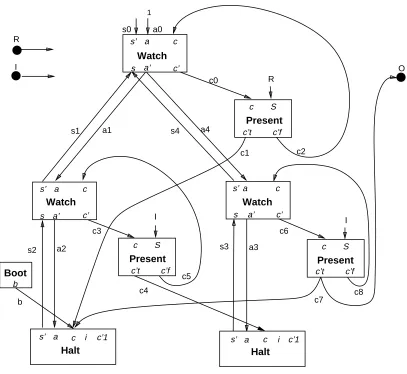
The corresponding circuit is drawn in Figure 1. It has two input pins forIand Rand one output pin for Ø. There are four kinds of cells, calledBoot,Watch,Present, andHalt. Cell output pins are primed.
The Boot andHalt cells each contain one register, assuming to initially contain value 0 and to be clocked by the global circuit’s clock. The other cells are purely combinatorial.
ThePresent cells are used forpresent andwatching source statements, each source
“watching S” statement being conceptually rewritten into “watch present S”; This
slight syntactic modification simplifies the cells and makes it easy to implement boolean expressions.
The circuit contains three sorts of wires: the selection wires s0–s5, the activation wires
a0–a5, and the control wires c0–c8. The unconnected i and c 0
1 pins of Halt cells corresponds to other wires unused here and described later on. Whenever two wires go to the same place, they are implicitly assumed to be combined by anorgate.
The selection and activation wires go in reverse directions and form a tree that is called the
skeleton of the circuit. This tree is determined by the nesting ofhalt,watching, and||
c3 c1 R I R I I a c s’
s a’ c’ Watch
a c s’
s a’ c’ Watch Present c S Present c S s0 s1 s2 s3 s4 a0 a1 a2 a4 a3 c0 c2 c4 c5 c6 c8 c7 O c s’
s a’ c’ Watch
Present c S
c’t c’f
c’t c’f
c’t c’f
c i s’ a i s’ Halt Halt c’1 c’1 a Boot b b c a 1
Figure 1: first example
The selection wires are used to determine which part of the circuit can be active in a given state: in our example, bothawaitstatements are in mutual exclusion, and only one of them can be active at a time. When the firstawaitis active, the wiress2,s1, ands0are set to 1. When the secondawaitis active, the wiress4,s3, ands0are set to 1. The sources of the selection wires are theHaltcell registers. The upper selection wires0is unconnected here, but we left it there to emphasize the structural character of the translation.
The activation and control wires bear the flow of control. The activation wires handle preemption between watching statements. In our example, the outermost watching
preempts the innermost one: by the semantics of
Esterel
, if R is present, the outermostwatching terminates without letting its body execute. The upper activation wirea0 is
always set.
[image:30.612.95.502.77.451.2]Boot
(
n := 1 b = ¬n
Watch
8
>
<
>
: s
0
= s
c 0
= sa
a 0
= c
Present
(
c 0
t = cS c
0
f = c¬S
Halt
n
s 0
:= c+ (as)
The notation is that of
Palasm
: ‘+’ is or, ‘’ is and, ‘¬’ is not, an equality is valid at alltimes, and a register is denoted by ‘ := ’. Registers are supposed to contain initially 0. In the sequel, we say that a wire is high or set if it has value 1 and low or reset if it has value 0. We say that a register is set if it gets value 1 and reset if it gets value 0. Signals are assumed to be present when their wire is set and absent when their wire is reset.
The output signalbof the Bootcell is high at first clock tick and remains then low. For
a Halt cell, the value of the output signal s 0
is initially low and then that of c+ (as)
delayed one clock cycle. Hence a register is set either if an incoming control wire is set or if the activation wire is set and the register was already set3. The definition ofHaltis only temporary: further pins will be added in Section 5.2.
A Sample Execution
At boot time, theHaltcell registers contain 0 and the selection wires are all low; the boot control wirebis high. Because of the cell equations, all other wires are low. Hence the only effect is to set the leftmostHaltregister.
On next clock tick, assume that I is present andR is absent. Thens2, s1, and s0are set by theHalt register. Sincea0is always set, the control flows down by settingc0that triggers the test forRin the upperPresent cell. SinceRis low, the control flows through thec
0
f pin and setsc2, which is connected to thecinput pin of theWatchcell. This pin is
directly connected to thea 0
output pin, and the control flows though a1anda4(which are connected with each other and form in fact a single equipotential). Since boths2 and a1
are high, the leftmostWatchcell setsc3and the leftmostPresentcell setsc4sinceIis present. This sets the rightmostHaltregister. Sinces4is low, the rightmostWatchcell is inactive. Having no incoming control set, the leftmostHaltregister is reset. This terminates the first “await I” statement.
On next clock tick, if I is present, the execution is symmetrical: the rightmostHalt is
3
The multiplication by s is there to prevent setting the second Halt register in a term such as
“do halt; halt watching S00
reset and the leftmost one is set. The wires set ares3,s4,a0,c0,c2,a1=a4,c6, andc7. Sincec7is also connected to the output Ø, this output is set. If insteadRis present, the wires set ares3,s4,a0,c0,c1, and one is back to the state just after boot. If neitherInorRare present, then the wires set ares3,s4,a0,c0,c2,a1=a4,c6,c8, anda3, and the state is simply restored as expected.
Relation with the Haltset Coding
Intuitively, the relation between our circuit and the haltset coding of derivatives is as follows:
A state of the circuit is a set ofHaltcells set to 1. It is therefore exactly a haltset.
The selection wires just compute the + and labels of statements, + being represented
by a 1 in the selection wire.
Sending the control to the translation of a subterm stat1by setting an incoming control
wire amounts to execute stat1. For example, settingb executes the whole statement,
settingborc1execute the firstawait I, and settingc4executes the secondawait I.
Sending the control to the translation of a subterm stat1by setting its incoming activation
wire amounts to executeR(stat H
1 ) if stat1is labeled by + inH, i.e. if the corresponding
selection wire is set.
Hence, in a haltsetH and an inputI, the circuit just mimics the behavioral proof ofR(stat H
) inI. This points will be made very precise in Section 7.
Notice that theBootcell is not really necessary since the initial state can also be recognized as the only state where allHaltcells have value 0, that is where the wires0is low. We could as well connect thebwire to the negation ofs0. However, it is convenient in practice to add the auxiliaryBootcell to reduce the length of wires and the number of logical levels.
5.2 Translating Parallel and Exceptions
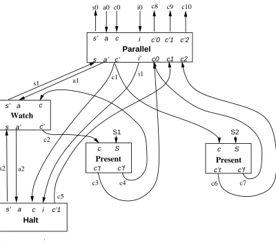
The most complex operator is of course the parallel one, since it must synchronize the termination of its branches and propagate exceptions. Consider the following program fragment:
trap T in await S1 ||
present S2 then exit T end end
The corresponding circuit fragment is shown in Figure 2. The leftmostWatch-Present
c
a s’
s a’ c’
Watch
Present
c S
c’t c’f
a i
s’
Halt
a s’
s a’ c0
c’0
c1 c’1
c2 i
i’
c’2
Parallel
Present
c S
c’t c’f c
c’
c
c’1
s0
s1
s2
a0
a1
a2
c0
c1
c2
c3 c4
c5
c6 c7
c8 c9
i0
i1
c10
S1 S2
[image:33.612.83.483.79.432.2]c
Figure 2: second example
“present S2”, (where “else nothing” was omitted as usual). The branches are simply
put in parallel and synchronized by theParallel cell. The circuit fragment starts when it receives control by setting thec0wire.
TheParallelcell has two parts: the fork part, which involves the six leftmost pins, and
the synchronization part, which involves the eight rightmost ones.
The fork part is simple: selection wires are gathered by an or gate and activation and control are dispatched to branches.
The synchronization part is more subtle. The pins c0, c1, and c2 record the different
termination modes according to their codes defined in section:c0 means termination,c1 means
halt, andc2 means exitingT. With each termination pinciis associated a continuation pinc 0
i.
(In fact,c 0
1 is not really a continuation in a usual sense: it is recursively linked to thec1 entry
As explained in Section 3, the synchronization realized by the parallel amounts to compute the max of the termination codes of its branches and to only activate the corresponding continuation. It therefore uses a priority queue.
In our example, the left branch can halt, as signaled by setting wire c5, or terminate, as signaled by setting wirec3. The rightmost branch can terminate or exit T as respectively signaled by setting wires c7andc6. Since exitingTor terminating the parallel lead to the same continuation, the continuations wiresc8andc10will reach the same input pin in any global circuit in which our fragment is placed.
When the right branch exitsT, the leftmost branch must be killed; technically, itshalt
statements must be removed from the current haltset. This is the role of the inhibition wire
i1that sends an inhibition signal to thehalt register. In an actual execution context, the inhibition signal can also come from an enclosing parallel statement itself killed by some trap exit. It is then received on piniby the wirei0.
The final equations of theParallelandHaltcells are:
Parallel 8 > > > > > > > > > > > > > > < > > > > > > > > > > > > > > : s 0 = s a 0 = a c 0 = c c 0
2 = c2
p1 = c 0
2
c 0
1 = c1¬p1
p0 = c1 +p1 c
0
0 = c0¬p0
i 0
= i+p1
Halt
(
c 0
1 = c+ (as)
s 0
:= (c 0
+ (as))¬i
where p0 and p1 are local wires used to compute the parallel continuation and inhibition values: ifciis the selected continuation,ciis set and all continuationscjare reset forj i,
andi 0
is set ifp2is.
A Sample Execution
Assume the circuit receives control byc0and therefore setsc1.
Assume S2 is present. Then c5 is set by the Halt cell and c6 is set by the right
Present cell. The parallel cell selects the appropriate continuationc10 and inhibits
Assume insteadS2is absent. Then c5 is set by theHalt cell and c7 is set by the
rightPresentcell. The selected continuation isc9; it signals halting to an eventual enclosing parallel statement. Since the inhibition wirei1is low, theHaltcell register is set. The circuit then remains in the same state in further clock cycles as long as the activation wirea0remains high andS1remains low: the wires set ares2,s1,s0,a1,
c2,c4,a2,c5, andc9. Ifa0remains high andS1is reset, the wires set ares2,s1,
s0,a1,c2,c3, andc8. The whole construct terminates and the register is reset since
c1anda2are low. The incoming activation wirea0can also become low before S1
occurs, for example because an enclosing watchdog elapses. Then theHaltregister is also reset.
General Parallel Cells
In fact, the size of the priority queue in a parallel cell depends on the number of nested traps exited from within its source parallel statement. The number of pinsci;c
0
ifor i 2
corresponds to the number of enclosing traps. With no trap, there is no such pin. The example explained one level of trap. With two levels of traps, as in
trap U in trap T in
. . .||. . .
end end
there would be a pinc2 forTand a pinc3 forU, and so on.
5.3 Summary of the Translation
The translation is done by connecting together cells corresponding to source statements. The cells are the same for all programs, but the parallel cells have a variable continuation arity according to the number of enclosing traps.
The logical skeleton of the translation is given by the tree ofHalt,Watch, andParallel
cells which mimics the tree of sourcehalt,watching, and||statements. Each edge of the tree is composed of an upward selection wire and a downward activation wire. Two sets of wires reinforce the skeleton: control wires that signal halting and go upwards fromHalt
andParallel cells toParallel cells, and opposite inhibition wires that force resetting
theHaltregisters in case of exceptions.
In addition to the above cells, one finds aBootcell used to boot the circuit, andPresent
cells generated by source present and watching statements. These cells are linked together and to skeleton cells by control wires. EachPresent cell also receives as input a
signal wire. Signal wires come either from input signal pins or from local signal cells, which
wires is determined by a continuation analysis, see Section 6.
5.4 Optimization
The reader may find that our circuits contain lots of wires and of logical levels, even for simple programs. In fact, this is because they are obtained by a strucural translation process and there is much room for automatic optimization. Many wires are simply connected with each other. Many generated logical functions are readily grouped by logic optimizers. Constant folding can also be used: for instance, the top activation wire is always set; using this fact, one can statically simplify many gates.
Therefore, our circuits should not be directly implemented; they should instead be given as input to logic optimizers. We presently use optimizers based on Binary Decision Dags (or BDD’s), see [11, 15, 24]. They drastically reduces the actual size of circuits. They can also discover redundancies between registers and suppress some of them [7].
Altogether, we believe that we can obtain final circuits that are as good as carefully hand-designed ones. Because of the power and efficiency of BDD-based optimization techniques, we think there is no need to search for a more sophisticated translation process.
5.5 The Translation is Sometimes Incorrect
Our translation does not translate correctly all programs. There are difficulties with local signals and with loops over parallel statements.
First, we have allocated a single wire for a local signal. But even within a single reaction, an
Esterel
signal can have several independent avatars. Consider a statement of the formloop
signal S instatend
end
When the body terminates, it is restarted at the same instant with a fresh signalS. This is made obvious by unfolding the body to get
loop
signal S instatend;
signal S instatend
end
which is semantically equal and where there are clearly two distinct signals.
The second incorrectness is more subtle. The translation of the statement
loop await S end
is correct, but the translation of the equivalent statement
loop await S ||
nothing end
is not since it involves an unstable combinatorial loop through the parallel synchronizer: when
Soccurs, the parallel terminates and the loop makes it halt at the same time on await S. But halting justs inhibits the termination that should provoke it, hence the combinatorial loop. Unfolding the body would solve the problem; it still builds a combinatorial loop, but this time a safe one.
The
Esterel
software checks for sufficient conditions for translation correctness. We are presently investigating a more powerful translation that will correctly translate allEsterel
programs. It will be reported in another paper.6 The Formal Translation to Hardware
We define the translation formally and prove its correctness in absence of bad loops over parallels. As explained in Section 5, we assume all local signal declarations to be at toplevel in the module body.
6.1 Circuits
We consider a circuit to be given by a set of input wires, a set of output wires, a set of local
wires and a set of wire definitions that define output and local wires. There are two kinds of
wire definitions:
An implication definitionw ( expexpresses a partial definition, read as “connectexp
tow”. There can be several implications per wire.
A register definitionw := expdefines a wire to be initially 0 and then the value ofexp
at previous clock cycle. There can be only one register definition per wire.
Given a circuit C and a wire w, the set of implications w ( exp i in
C defines w as w =
W
i exp
a wire whas no definition, it is considered to have an empty set of implication definitions,
and therefore to be defined byw = 0. To stress the fact that a wire has a single implication
definition in a circuit, we can write this definition using ‘=’ instead of ‘(’.
Given any register state and any input, the semantics of a circuit is classically defined as a unique fixpoint of the equations, and a circuit is correct if a unique fixpoint always exists in any (reachable) state. We assume this to be well-known.
6.2 The Translation Environment
The formal translation is done by natural semantics inference rules [21]. The sequents have the form ` stat!C, whereis a wire environment, stat is an
Esterel
statement, andCis the resulting circuit.
As in natural semantics or in
PROLOG
, allocation of new wires is implicit and done when encountering free variables. To make things clear, we shall comment each rule and explicitly tell which are the newly allocated wires.The environment is made of several wires, whose functions have been explained in
Section 5. It contains the following fields
An incoming control wirec.
A selection wires.
An activation wirea.
An inhibition wirei.
A vector of continuation wires~c. The wire~c
0corresponds to termination, the wire
~c
1
corresponds to halting, the wire~c k+2
corresponds to exitk+ 2, that is to exitingktrap
levels.
A set of signal wiresS, one for each input, output, or local signalS. For simplicity,
we assume that all local signals have distinct names; then all local signal wires can be preallocated.
We use the classical dot notation to get environment components: for instance,:cdenotes
the control wire of . Given an environment , we shall often need to consider another
environment 0
that differs fromby the value of one field, say by changing:cintoc 0
. We then write
0
=[c c 0
]. The notation extends naturally when changing several fields.
To translate a module, we allocate a boot control wire b and a register n of equations
b = ¬n; n := 1 as in Section 5, a dumy selection wires, two dummy wiresc0andc1for
respectively input and output signals as inputs and outputs to the circuit. We translate the module body in the environment
0= (b;s;1;i;(c0;c1); ~S)
6.3 The Translation Rules
The cells of Section 5 were useful for an intuitive explanation, but in rules it is simpler to produce directly equations.
For anothingstatement, we connect the incoming control to the termination continuation wire.
` nothing ! :~c
0
( :c
For ahalt statement, we connect the incoming control to the halt continuation wire, to signal halting to an enclosing parallel statement. We allocate a new selection wires
0
defined as a register with input as explained in Section 5. We connect it to the environment selection wire:s.
` halt ! :~c 1
( :c+ (:a:s) :s ( s
0
s 0
:= (:c+ (:a:s))¬:i
For anemitstatement, we connect the incoming control to the termination wire and to the signal wire.
` emit S !
:~c 0 ( :c
:S ( :c
For a sequence, we allocate a new wire c 0
for control transmission. We translate the first statement withc
0
as termination and the second statement withc 0
as incoming control.
[~c
0
c 0
] ` stat1 ! C1
[c c 0
] ` stat2 ! C2
` stat1;stat2 ! C1 C2
For a loop, we allocate a new wirec 0
to handle looping and we connect the incoming control to it. We translate the body withc
0
[c c 0 ;~c 0 c 0
] ` stat ! C
` loopstatend ! c 0 ( :c C
For apresentstatement, we allocate two new control wiresc1andc2; thenc1is set when
the incoming control is present and the signal is present, whilec2 is set when the incoming
control is present and the signal is absent. We translate the branches with c1 and c2 as
respective incoming controls.
[c c1] ` stat1 ! C1 [c c2] ` stat2 ! C2
` present S thenstat1elsestat2end !
c1 = :c:S c2 = :c¬:S C1
C2
For awatching statement, we allocate a new selection wires 0
and connect it to:s, and we
allocate a new activation wirea 0
. The outgoing activation wirea 0
is set if ifs 0
and:aare set
and the signal is absent. The outgoing termination wire:~c
0is set if
s 0
and:aare set and the
signal is present.
[s s 0
;a a 0
] ` stat ! C
` dostatwatching S !
:s ( s 0
a 0
= :a:s¬:S
:~c
0
( :a:s:S
C
The parallel rule is of course the most complex one. It follows exactly the intuitive explanation given in Section 5. We allocate a selection wires
0
connected to:s, an inhibition wirei 0
, a continuation vector~
c 0
of the same lengthkas:~c, and a priority vector~pof lengthk 1. We
recursively translate the body with the new selection, inhibition, and continuation wires. Then we establish the priority queue to compute the outgoing continuations and the new inhibition wirei
0
k=j:~cj
[s s 0
;i i 0
;~c ~
c 0
] ` stat1 ! C1
[s s 0
;i i 0
;~c ~
c 0
] ` stat2 ! C2
` stat1||stat2 !
:s ( s 0 :~c k 1 ( ~ c 0 k 1 ~ p k 2 = ~ c 0 k 1 :~c k 2 ( ~ c 0 k 2 ¬~p
k 2 ~ p k 3 = ~ c 0 k 2
+~p k 2
. . .
~ p
0 = ~ c
01
+~p
1 :~c 0 ( ~ c 00
¬~p
0
i 0
=
(
:i ifk3 :i+~p
1 if
k>3
C1
C2
For a trap, we shift by 1 all wires in :~c after position 2 and we insert the termination
continuation:~c
0at exit position 2. The vector notations are obvious.
[~c (:~c
0
;:~c
1
;:~c
0)
:~c
2::
] ` stat ! C
` trap T instatend ! C
For anexit, we connect the incoming control to the appropriate continuation.
` exit T
k
! :~c k
( :c
For a local signal declaration, we simply translate the body since the signals have been pre-allocated.
` stat ! C
` signal S instatend ! C
7 Correctness of the translation