SECOND REVISION OF MS # 01-257
The effect of prosthesis design on vibration of the reconstructed
ossicular chain – a comparative finite element analysis of four
prostheses
D.J. Kelly, MSc & P.J. Prendergast, PhD
Department of Mechanical Engineering, Trinity College, Dublin, Ireland.
A.W. Blayney, MCh, FRCSI
Department of Otolaryngology, Mater Hospital, Eccles St., Dublin, Ireland.
Address correspondence to: Patrick J Prendergast, Ph.D. Bioengineering Group
Department of Mechanical Engineering Parsons Building
Trinity College Dublin 2 Ireland
Tel: +353.1.6081383
Fax: +353.1.6795554
Email: [email protected]
First submitted: 23 October, 2001 Revision submitted: March 8, 2002 Second revision submitted: 29 April, 2002
Acknowledgements
The effect of prosthesis design on vibration of the reconstructed
ossicular chain – a comparative finite element analysis of four
prostheses
Abstract
Hypothesis: We hypothesize that the differences in the bioacoustic performance of ossicular replacement prosthesis designs, and insertion positions, can be quantified using finite element analysis.
Background: Many designs of prosthesis are available for middle ear surgery. Materials used, and the shape of the implants, differ widely. Advances in computer simulation technologies offer the possibility of replicating the in vivo behavior of the different prostheses. If this can be achieved, insight into the design attributes required for improved biofunctionality may be determined.
Methods: Micro CT scanning and NMR imaging were used to obtain geometric information that was translated into a finite element model of the outer and middle ear. The forced frequency response across the hearing range of the normal middle ear was compared to the middle ear reconstructed with partial and total ossicular replacement prostheses (Xomed, Jacksonville, FL and Kurz, Dusslingen Germany).
Results: The amplitude of vibration of the footplate was more similar to the normal ear when a Kurz TORP was implanted compared to when a Xomed TORP was implanted; this may be attributed to the latter’s titanium link. PORP prostheses were stiffest and had lower umbo vibrations and higher stapedial footplate vibrations. In all cases bar one the vibration of the prostheses had resonances that caused the vibration of the stapes footplate to be noticeably different from normal.
Introduction
Two common classifications of middle ear prosthesis are the partial ossicular replacement
prosthesis (PORP), which connects the tympanic membrane to the head of the stapes, and the
total ossicular replacement prosthesis (TORP), which connects the tympanic membrane to the
stapes footplate. A wide range of prostheses designs [1] and materials [2] are available, and
this suggests that the design criteria for optimal biofunctionality have yet to be fully
established. The primary design criteria for ossicular replacement implants has been ease of
insertion and biocompatibility of the implant materials – however, recent studies have
additionally focused on the vibro-acoustic biofunctionality of the implants [3]. With recent
advances in experimental techniques, such as laser Doppler vibrometry, and in bioengineering
analysis methods, such as finite element modelling, the possibility of conducting pre-clinical
design analyses to assess biofunctionality has become possible.
Comparing various prostheses using laser vibrometry, Goode and Nishihara [4]
determined that, for optimal sound transmission, a prosthesis should weigh between 10 and 40
mg, should provide proper tension between the tympanic membrane and the stapes, and
should form an angle of less than 30 degrees with the tympanic membrane. Meister et al. [5]
used a mechanical middle ear model to study the influence of prosthesis mass and stiffness on
acoustic response. They concluded that increasing the prosthesis stiffness improved the high
frequency response at the expense of the low frequency response. Prosthesis mass was
predicted to have the greatest effect on prosthesis performance with a high mass causing a
reduction in performance at high frequencies – this lead to the conclusion that prostheses
should be as light as possible for optimal high frequency transmission. Goode [6] proposed
that there is an advantage to designing prostheses with improved acoustic performance in
certain frequency ranges; he proposed that, for example, a prosthesis designed for improved
high frequency response could be used in a patient with a high frequency sensorineural
component to the hearing loss. Using laser Doppler vibrometry, Vlaming and Feenstra [7]
concluded that, for PORPs, the critical issue was to keep the angle between the prosthesis and
instead of a ‘piston-like’ translation. For TORPs Vlaming and Feenstra [7] predicted better
results when the prosthesis was placed onto the center of the footplate because greater rotation
of the footplate was seen when the prosthesis was placed off-center. Hüttenbrink [3] also
emphasized the influence of prosthesis alignment in middle ear reconstruction by showing,
theoretically, that a aligned prosthesis transports sound more effectively than an inclined
prosthesis.
Finite element modelling has been used to analyze middle ear mechanics, the most
comprehensive model being that of Wada et al. [8,9]. It includes the ear-canal, tympanic
membrane, ossicles, the various muscles and ligaments of the middle ear as well as the middle
ear cavities. This model was used to study the vibratory patterns of the ossicular chain across
a broad frequency range, as well as to examine pressure transmission across the middle ear.
Eiber [10] and Eiber et al. [11] used a computational model based on multi body dynamics to
show that middle-ear dynamics is fundamentally affected by otosclerosis, the presence of the
ligaments, and the nature of prosthetic reconstruction. Finite element modelling has also been
used to study the performance of middle-ear prostheses [12-16]. Ladak and Funnell [12] have
used the finite element method to show that the location of a prosthesis along the manubrium
of the malleus did not affect the motion of the stapedial footplate as long as the joints were all
rigid. A finite element study of the effect of a PORP and a TORP on middle-ear dynamics has
been reported by Prendergast et al. [15] and Ferris and Prendergast [16]. These studies
showed how a prosthesis fundamentally alters the dynamical response of the middle ear. By
comparing the vibration of the umbo and footplate of the normal middle ear to the surgically
reconstructed middle ear, it was shown that the stiffness of the prosthesis had a significant
effect on the vibratory coupling between the tympanic membrane and the stapes. The authors
concluded that the function of the malleus-incus-stapes arrangement was to provide a suitable
stiffness for the mechanical connection between the TM and the oval window, and therefore
that a critical design requirement for a prosthesis should be to match the stiffness of the
In the present work, a more sophisticated finite element model has been developed
and used to analyze a greater range of prosthesis designs. We hypothesize that the differences
in biofunctionality of ossicular replacement prosthesis designs, and insertion positions, can be
quantified using finite element analysis, and that the predicted differences correlate with
observed clinical performance. If this is true then computer-based design of middle ear
implants for improved biofunctionality could be attempted.
Methods
The method used to compare the four implants is finite element analysis. This is a
computer-based method for the analysis of the physical behavior of structures. The method relies on an
appropriate specification of the following features of the system: the geometry of the implant,
bones and soft-tissue structures; the material properties (elasticity, density, etc.); and the
boundary conditions (i.e. the connections of the geometry to the surrounding tissues). In a
previous model [11,12] the geometry of the ossicles was determined indirectly from the
measurements of Kirikae [17]. In this model the geometry of the ossicles will be determined
directly from a micro-computed tomography scan.
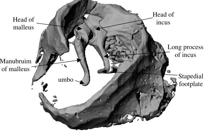
Geometry: Four sets of ossicular chains were removed from temporal bones. One
ossicular chain was successfully removed intact and scanned using microcomputed
tomography (µCT) scanning (Scanco, Zurich, Switzerland) – this image is shown in Fig. 1.
All bones were then separated and stored in 10% formalin. Using a coordinate measuring
machine, all twelve ossicles were measured, and the set of ossicles of average size was
selected for individual µCT scanning. Cross-sectional scans of the ossicles were taken every
25µm. Using the finite element package ANSYS (Version 5.5, Providence, RI, USA), the
µCT scans were used to create a geometrically precise finite element model of the ossicles
with 8-noded hexahedral finite elements (SOLID45). The geometry of the ear-canal and
tympanic membrane was determined using nuclear magnetic resonance spectroscopy [18],
(FLUID30) and the tympanic membrane was modelled using shell elements (SHELL93) that
accounted for the tympanic membranes varying thickness and material properties. The
tympanic membrane has a maximum thickness of 0.8mm in the pars flacida, and a minimum
thickness of 0.1mm in the pars tensa. Five ligaments of the middle ear were modelled using
beam elements (BEAM4): the anterior ligament of the malleus, the lateral ligament of the
malleus, the posterior ligament of the incus, the superior ligament of the malleus and the
superior ligament of the incus (the latter two had been omitted in the previous model [15,16]).
Each beam element was 0.8mm long and 0.5mm × 0.5mm. The location of these ligaments
was estimated from anatomical text books [19,20]. The two muscles of the middle ear, namely
the tensor tympani muscle, which is a long slender muscle and therefore modeled with a
single beam element (BEAM4), and the stapedius muscle which is shorter and therefore
modeled with eight three-dimensional 8-noded elements (SOLID45). The tensor tympani
muscle was taken as 3mm long and 0.5mm30.5mm in cross-section, while the stapedial
muscle was taken to be 2mm long and 0.43mm30.46mm in cross-section.
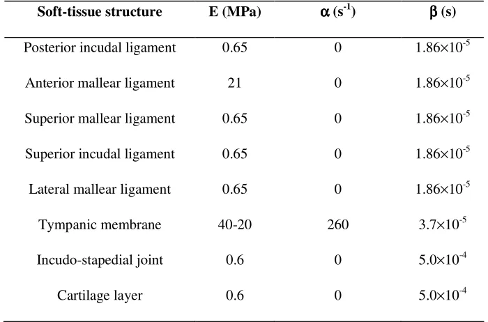
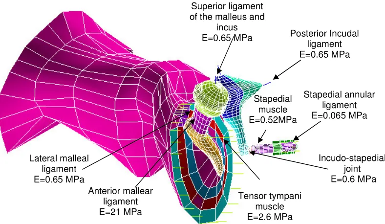
Material properties: The Young’s modulus of the middle ear bones and ligaments
were taken from Wada et al. [9] and are shown in Fig. 2. The densities of the ossicles are
derived from the experimental work of Kirikae [17]. The Young’s moduli of the tympanic
membrane increases in the radial direction from 20 MPa at the periphery to 40 MPa at the
centre, and decreases in the circumferential direction from a value of 40 MPa around the
periphery to a value of 20 MPa around the manubrium, see [15,16]. Raleigh damping was
employed to model the damping of the soft-tissue structures of the middle ear. Raleigh
damping assumes that damping is a linear combination of mass and stiffness according to:
[ ]
C =α[ ]
M +β[ ]
K (1)The values of α and β for the various soft-tissue structures of the middle ear were taken from
Wada et al. [8] (data given in Table 1). To model the damping due to the annular ligament of
the stapedial footplate and the fluids of the inner ear, impedance data from Merchant et al.
the oval window. The resistive component of the impedance at a frequency where the reactive
component is equal to zero was determined [16]. The acoustic damping is equal to the
resistive component of the impedance, which was measured by Merchant et al. [21] to be 70
GΩ at 3000 Hz, and hence the mechanical damping can be calculated by multiplying the
acoustic damping by the area of the stapedial footplate squared. The mechanical damping
coefficient was calculated to be cm = 0.717 Nsm-1, based on a stapedial footplate area of
3.2mm2 [21].
Boundary conditions: To model the annular ligament of the tympanic membrane the
periphery of the tympanic membrane is constrained using spring elements; this is described
diagrammatically by Prendergast et al. [15]. The end-nodes of all the ligaments and muscles
were fixed to zero displacement. The incudomallear joint is assumed to be rigid and is
therefore modeled by coupling the malleus and incus with very stiff truss elements. The
incudostapedial joint is not assumed to be rigid; instead is modelled by joining the tip of the
incus to the head of the stapes with 159 8-noded hexahedral elements (SOLID45) with a
Young’s modulus of 6.0 × 10⁵ N/m2 which is a stiffness typical of ligamentous tissue. A
uniform pressure stimulus of 80 dB SPL is applied to the opening of the ear-canal, the concha,
as this sound pressure level (SPL) is used in experimental studies [22–25]. The completed
finite element model of the human ear is shown in Fig. 2.
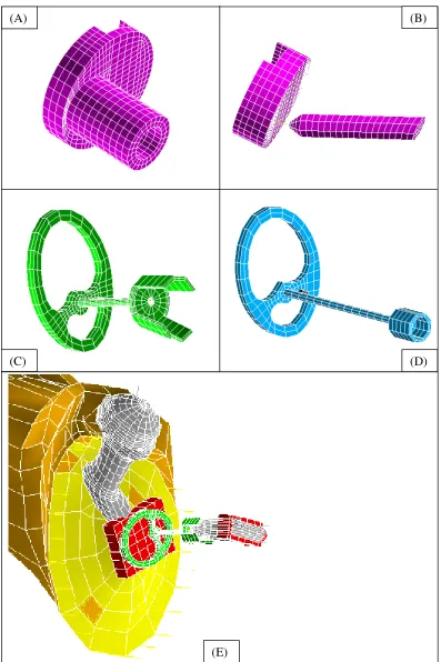
Prosthesis models: Four designs of middle-ear prosthesis are analyzed. These are,
(i) Xomed (Jacksonville, FL, USA) PORP (Ref: 0362), see Fig. 3(a)
(ii) Xomed (Jacksonville, FL, USA) TORP (Ref: 0321), see Fig. 3(b)
(iii) Kurz (Dusslingen, Germany) Bell-Tubingen PORP, see Fig. 3(c)
(iv) Kurz (Dusslingen, Germany) Aerial-Tubingen TORP, see Fig. 3(d)
The Xomed PORP was modeled using 1327 SOLID 45 elements, the Xomed TORP was
modelled using 1116 eight-noded (SOLID 45) elements and 3 beam (BEAM4) elements, the
Kurz PORP was modelled using 1129 eight-noded (SOLID 45) elements and the Kurz TORP
was modelled using 511 eight-noded (SOLID 45) elements. A Kurz Bell-Tubingen PORP
prostheses are manufactured from hydroxyapatite (Young’s modulus = 155 GPa, Poisson’s
ratio = 0.3) and the Kurz prostheses are manufactured from titanium (Young’s modulus = 116
GPa, Poisson’s ratio = 0.33). The Xomed TORP is unique in that it consists of a titanium link,
0.5mm long, which connects the base to the column of the prosthesis. Following the
manufacturer’s recommendations a piece of cartilage, 0.7 mm thick in this case and with a
Young’s modulus of 0.6 MPa, is placed between the Kurz prosthesis and the manubrium of
the malleus. This piece of cartilage is modelled using 36 eight-noded (SOLID 45) elements.
Raleigh damping is applied to the cartilage, see Table 1 for details. The prostheses are
connected to the malleus/tympanic membrane by merging several nodes around the periphery
of the prosthesis to the surrounding tissue.
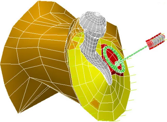
If the angle between the manubrium mallei and the stapes head is large, as it is in
some middle ears, it may be necessary to place the implant directly under the TM to avoid a
large angle between the TM and the implant [26]. To study the influence of prosthesis
position on vibro-acoustic response, a further model of the human middle ear was created
where the angle between the manubrium and the stapes is approximately 30 degrees greater
than in the normal case, see Fig. 4. This ear was reconstructed with a Kurz TORP placed
directly under the tympanic membrane, rather than beneath the manubrium of the malleus, as
shown in Fig. 5.
Results
Because the present finite element model has more accurate representations of the ossicle
bones and includes ligaments omitted from the model of Ferris and Prendergast [16], the
results are slightly different. The noteworthy differences are that the present model generally
predicts slightly higher amplitudes of umbo and footplate vibrations, and the two new
ligaments added seem to reduce the resonance dip at 850Hz.
In an attempt to confirm that the finite element model gives satisfactory predictions,
the vibration of the umbo as a function of frequency is compared to experimental studies [22–
frequencies below 500 Hz compared to the predictions of the present finite element model. At
higher frequencies however, the predictions are quite close to two of the curves of Vlaming
and Feenstra [22] including a large ear-canal resonance peak above 4 kHz; this indicates that
the present model is representative of a healthy middle-ear. The umbo displacement
calculations of Goode et al. [23]are noticeably greater in magnitude than the predictions of
our computational model across the entire frequency range. There is no evidence of an
ear-canal resonance peak in the data of Goode et al. [23], however this may be due to the fact that
the sound delivery system used in their experiment was inserted into the ear-canal, close to
the tympanic membrane. Kempe et al. [24] measured umbo displacements as a function of
frequency measured using laser Doppler vibrometry. Their results are similar in magnitude, if
not as smooth, to the finite element results, except for a much larger resonance peak at 3 kHz.
The ear-canal resonance peak is very obvious is some experimental data [24], and not in
others [23]. Obviously this resonance peak will depend on the length and shape of the
ear-canal, but also on the location of the sound delivery system. Finally the finite element
predictions are compared to the laser Doppler vibrometry measurements of Nishihara and
Goode [25]. This curve is very smooth, and intermediate in magnitude between the data of
Goode et al. [23] and the finite element data.
The model predictions for the amplitude of vibration of the umbo for the normal
middle ear can be compared to the predictions for the amplitude of vibration of the umbo in
the middle ear reconstructed with each of the PORPs. It is predicted that umbo displacement
is lower with the Xomed PORP than with the Kurz PORP, see Fig. 7 (a). Since the Xomed
PORP is very stiff this reduction in umbo displacement does not result in a reduction in
footplate displacement compared to the normal middle ear, see Fig. 7 (b) where the Xomed
PORP reproduces the behavior of the normal ear quite well. At higher frequencies the
amplitude of vibration of the stapedial footplate is greater with the Xomed PORP compared to
the Kurz PORP. There is no evidence of the anti-resonance dip seen with the Kurz PORP at
Reconstructing the middle ear with a Xomed TORP significantly alters the response
of the umbo and the stapedial footplate compared to the normal ear, see Fig. 8(a) and Fig.
8(b). A better response is obtained with the Kurz TORP where the stapedial footplate
vibration closely matches that of the normal ear, although a significant resonance dip at
approximately 1.9 kHz is predicted. The response of the Xomed TORP, on the other hand,
seems to vary considerably and does not track the performance of the normal ear at all well
across the frequency range.
The vibroacoustic behavior of a middle ear with a large angle between the manubrium
mallei and the stapes head can be compared to both the normal ear and the reconstruction of it
with the Kurz TORP placed onto the tympanic membrane in a postero-superior location. The
stapedial footplate response with the Kurz TORP is very similar to the normal middle ear, see
Fig. 9; interestingly the Kurz PORP generates a high frequency response almost matching that
of the normal middle ear. By comparing the vibration of the stapedial footplate of the
reconstructed middle ear with the prosthesis placed under the manubrium of the malleus to the
case when the prosthesis is placed directly under the tympanic membrane (Fig. 10), it is
predicted that the tympanic membrane is a better location for high frequency transmission.
Discussion
We hypothesized that finite element modelling can be used to compare the biofunctionality of
middle ear implants. To test this hypothesis, a µCT scan of the ossicles was used to create an
anatomically accurate finite element model of the ossicular chain. Many modelling
assumptions have been made, however, in creating this model of the middle ear. The middle
ear cavities, which have been shown by Wada et al. [8] to reduce the amplitude of vibration of
the ossicles at low frequencies, have not been included in this model. The ear-canal wall has
been assumed rigid and the stapedial annular ligament is assumed to have a constant
thickness.
Assumptions have also been made when modelling the different middle-ear
the nature of the contact (wet or dry, etc.) between the implant and the bone and, for the Kurz
PORP, will depend on the degree of crimping of the bell onto the stapes head. To facilitate
intercomparison of prostheses, it was convenient to assume secure fixation according to ideal
conditions and therefore prostheses were modelled as being as firmly attached to the
supporting tissues in all cases.
Despite these assumptions, the predictions of the model for the normal middle ear
compare well to numerous experimental studies [22-25], as shown in Fig 6. A relatively flat
umbo response is predicted below 0.5 kHz, followed by a gradual roll off in response to 4
kHz that is interrupted by a peak and trough between 0.8 and 1 kHz due to resonance of the
middle ear. Including the middle ear cavities would be expected to reduce the magnitude of
vibration at lower frequencies (Wada et al. [8]). Resonance of the ear-canal at approximately
4 kHz introduces a peak in the umbo response. Evidence of such a resonance peak is observed
in two of the data sets of Vlaming and Feenstra [22] at 5 kHz, although not to the same extent,
and in the data of Kempe et al. [24] at 3 kHz to a greater extent. Above 4 kHz there is a sharp
decline in the amplitude of the umbo vibration, similar to the trend in the experimental data
[22,24].
The middle ear reconstructed with both the Kurz and Xomed PORPs produces an
umbo and stapedial footplate response similar to that calculated for the normal middle-ear, see
Fig 7 (a) and Fig. 7 (b) – however note that the Xomed PORP has a noticeably lower umbo
displacement. The most noticeable difference between the two PORPs is that the Kurz PORP
exhibits a dip in response at approximately 1680 Hz, its first resonance frequency, while no
resonance dip is predicted for the Xomed PORP. This result might be due to the fact that the
notched head of the Xomed PORP provides a more stable and rigid fixation to the manubrium
mallei than does the pivot-like connection between the Kurz prosthesis and the manubrium
that makes it (the Kurz PORP) more flexible and susceptible to tilting during resonance.
Increasing the Young’s Modulus of the cartilage between the Kurz PROP and the manubrium
by a factor of one hundred, and hence increasing the rigidity of the connection between
not shown). This result would also suggest that resorbtion or damage to the cartilage strip
over time would fundamentally affect the performance of the prosthesis. Bending the head
plate of the Kurz PORP to fit the manubrium might result in a more stable fixation – however
this idea is not explored further in this paper. A stable prosthesis fixation is also believed to be
important for improved high frequency transmission, and the fact that the Xomed PORP has a
slightly better match to the stapedial footplate at high frequencies may support this. The fact
that placing a Kurz TORP directly onto the tympanic membrane, a seemingly more stable
location than the manubrium mallei, has resulted in a superior high frequency performance
(see Fig. 10) also supports this idea.
The predicted responses of the Kurz PORP and TORP are very similar. This
correlates with the clinical study of Zimmermann et al. [28] that found small differences in
performance between the two types of prostheses. The predicted differences between the
Xomed TORP and the Kurz TORP are more pronounced. This is primarily due to the fact that
the Xomed TORP consists of a flexible titanium link to aid surgical handling. This flexible
link reduces the stiffness of the prosthesis, and consequently introduces several resonances
into the response of the reconstructed ossicular chain. These resonances result in the peaks
and troughs seen in the response of the Xomed TORP (Fig. 8 (a) and (b)). The Kurz TORP is
not designed with a flexible link, and hence has a higher stiffness which explains why the
response of the umbo and stapedial footpate in the middle ear reconstructed with the Kurz
TORP approaches that of the normal ear, with the exception of the single resonance dip seen
at 1.9 kHz.
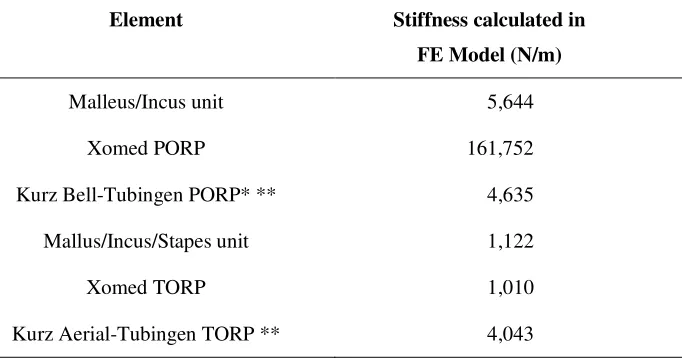
To explore further the importance of “implant stiffness”, a calculation for the stiffness
of each prosthesis was made by completely restraining the stapedial end of the prosthesis and
applying a force at the umbo pointing towards the centre of the stapes footplate. Using this
method, the static stiffnesses were found (Table 2). It can be seen that the Xomed PORP is
many times stiffer than the Kurz PORP; the latter is much closer to that of the malleus/incus
complex. It should be noted that the stiffness measurements of the Kurz prostheses includes
Xomed PORP is the reason why no resonance dips are brought into the response of this
prosthesis in the audible frequency range. The stiffness of the Xomed TORP is much lower,
being more comparable than the Kurz TORP to the stiffness of the malleus/incus/stapes
complex that it replaces. The lower stiffness of the Xomed TORP is predicted to cause
unconstrained resonances in the hearing range that may adversely affect the prosthesis’s
performance. Only one resonance dip is predicted with the Kurz PORP, and since it is the
Xomed TORP that has a stiffness closer to the intact ossicular chain, it suggests that the
ligaments play a role in the healthy ear in preventing large resonance vibrations by
constraining motion of the ossicular chain.
Comparing the performance of these prostheses leads us to conclude that it is
important to design an ossicular replacement prosthesis with an appropriate stiffness. The
stiffness of a prosthesis is one primary component of the impedance of the reconstructed
middle ear, another being the mass of the prosthesis. We propose therefore that the
fundamental design criterion for an ossicular replacement prosthesis should be to match the
impedance of the natural ossicular system. To highlight how the impedance of a prosthesis,
and hence its performance, can be varied by altering the mass and stiffness, we replaced the
bones of the middle ear in the finite element model with a spring and mass element
representing a prosthesis, and varied the mass and stiffness of these elements. Reducing the
mass of a prosthesis reduces its impedance at high frequencies (> 1kHz), see Fig. 11 (a),
which results in a higher stapedial footplate vibration at higher frequencies, see Fig. 11 (b),
whereas significantly reducing the stiffness reduces the high frequency response of the
prosthesis. Based on the results of this parameter variation study it is suggested that a
prosthesis should be as light as possible for improved high frequency transmission. A
prosthesis should also be sufficiently rigid to transport vibrations across the middle ear
without resonances of the reconstructed ossicular chain being brought into the audible
References
1. Lobel K, Ossicular replacement prosthesis. In: Hench L, Wilson, J. eds. Clinical Performance of Skeletal Prosthesis, London: Chapman & Hall, 1993.
2. Blayney AW, Erre JP, Williams K.R., Lesser TJ, Portmann M, Problems in alloplastic middle ear reconstruction. Acta Otolaryngology (Stockh.) 1992; 112: 322-7.
3. Hüttenbrink B, Mechanical aspects of middle ear reconstruction. In: Huttenbrink, K-B, ed. Middle Ear Mechanics in Research and Otosurgery, Technical University of Dresden: Dresden, 1997: 165-168.
4. Goode RL, Nishihara S. Experimental models of ossiculoplasty. Otolaryngol Clin North Am 1994; 27: 663-75.
5. Meister H, Walger M, Michenhagen A, et al. Standardized measurements of the sound transmission of middle ear implants using a mechanical middle ear model. Eur Arch Otorhinolaryngol, 1999; 256: 122-7.
6. Goode RL, The ideal middle ear prosthesis. In: Huttenbrink, K-B, ed. Middle Ear Mechanics in Research and Otosurgery, Technical University of Dresden: Dresden, 1997, 169-74.
7. Vlaming MSMG, Feenstra L, Studies on the mechanics of the reconstructed human middle ear. Clin. Otolaryngol., 1986;11:411-22.
8. Wada H, Koike T, Kobayashi T, In: Huttenbrink, K-B, ed. Middle Ear Mechanics in Research and Otosurgery, Technical University of Dresden: Dresden, 1997: 76-81.
9. Wada H, Metoki T, Kobayashi T, Analysis of the dynamic behavior of the human middle ear using a finite element method. J. Acoust. Soc. Am. 1992; 92, 3257-168.
10. Eiber A, Mechanical modeling and dynamical investigation of middle ear. In: Huttenbrink, K-B, ed. Middle Ear Mechanics in Research and Otosurgery, Technical University of Dresden: Dresden, 1997: 61-66.
11. Eiber A, Freitag H-G, Burkhardt C, Hemmert, W., Maassen, M., Jorge, J.J., Zenner, H.-P. Dynamics of middle ear prostheses – simulations and measurements. Audiol Neurootol 1999; 4: 178-184.
13. Koike T, Wada H, Kobayashi, T, Analysis of the finite-element method of transfer function of reconstructed middle ears and their postoperative changes. . In: Rosowski JJ, Merchant SN, eds, The Function and Mechanics of Normal, Diseased and Reconstructed Middle Ears, pp. 309-320, The Hague: Kugler, 2000.
14. Zahnert T, Schmidt R, et al. FE-simulations of vibrations of the Dresden middle ear prosthesis. In: Huttenbrink, K-B, ed. Middle Ear Mechanics in Research and Otosurgery, Technical University of Dresden: Dresden, 1997: 200-206.
15. Prendergast PJ, Ferris P, Rice HJ, Blayney AW, Vibro-acoustic modeling of the outer and middle ear using the finite-element method. Audiol Neurootol. 4, 185-91, 1999.
16. Ferris P, Prendergast PJ, Middle ear dynamics before and after ossicular replacement. J. Biomech. 2000; 33: 581-90.
17. Kirikae I, The Structure and Function of the Middle ear. Tokyo: Tokyo University Press, 1960.
18. McAvoy GJ, The development of a vibro-acoustic model of the human ear. M.Sc. Thesis, University of Dublin, 1995.
19. Gray’s Anatomy. 38th edition.Churchill Livingstone.
20. Martini FH, Fundamentals of Anatomy and Physiology. 4th edition. New Jersey: Prentice-Hall, 1998.
21. Merchant SN, Ravicz ME, Rosowski JJ, Acoustic input impedance of the stapes and cochlea in human temporal bones. Hearing Research 1996; 97:30-45.
22. Vlaming MSMG, Feenstra L,Studies on the mechanics of the healthy human middle ear. Clin. Otolaryngol., 1986; 11:353-63.
23. Goode RL, Ball G, Nishihara S, Measurement of umbo vibration in human subjects-method and possible clinical applications. Am J Otol 1993; 14: 247-51.
24. Kempe C, Stache N, Bormann M, Foth HJ, Laser Doppler velocimetry – a method supporting differential diagnosis of middle and inner ear disorders. In: Huttenbrink, K-B, ed. Middle Ear Mechanics in Research and Otosurgery, Technical University of Dresden: Dresden, 1997: 95-99.
26. Goode GL, Killion M, Nakamura K, Nishihara S, New knowledge about the function of the human middle ear: Development of an improved analog model. Am J Otol 1994; 15 (2): 145-154.
27. Eiber A, Freitag H-G, Schimanski G, Zenner HP, On the coupling of prostheses to the middle ear structure and its influence on sound transfer. In: Rosowski JJ, Merchant SN, eds, The Function and Mechanics of Normal, Diseased and Reconstructed Middle Ears, pp. 297-308, The Hague: Kugler, 2000.
Table 1: Young’s modulus and damping co-efficients of soft-tissue structures
Soft-tissue structure E (MPa) αααα (s-1
) ββ (s) ββ
Posterior incudal ligament 0.65 0 1.86×10⁻⁵
Anterior mallear ligament 21 0 1.86×10⁻⁵
Superior mallear ligament 0.65 0 1.86×10⁻⁵
Superior incudal ligament 0.65 0 1.86×10⁻⁵
Lateral mallear ligament 0.65 0 1.86×10⁻⁵
Tympanic membrane 40-20 260 3.7×10⁻⁵
Incudo-stapedial joint 0.6 0 5.0×10⁻⁴
Table 2: Stiffness calculations for middle ear and prostheses
Element Stiffness calculated in FE Model (N/m)
Malleus/Incus unit 5,644
Xomed PORP 161,752
Kurz Bell-Tubingen PORP* ** 4,635
Mallus/Incus/Stapes unit 1,122
Xomed TORP 1,010
Kurz Aerial-Tubingen TORP ** 4,043
* According to Eiber et al. [23], the stiffness is highly dependant on the nature of the coupling between prosthesis and bone. Values in the range 20 N/m to 120,000 N/m are reported.
Head of incus
Long process of incus
Stapedial footplate umbo
Manubruim of malleus
Head of malleus
[image:19.612.143.489.109.331.2]Fig. 2. The finite element model of the outer and middle ear. Tensor tympani
muscle E=2.6 MPa
Stapedial annular ligament E=0.065 MPa Posterior Incudal
ligament E=0.65 MPa Superior ligament
of the malleus and incus E=0.65 MPa
Anterior mallear ligament E=21 MPa Lateral malleal
ligament E=0.65 MPa
Incudo-stapedial joint E=0.6 MPa Stapedial
Fig. 3. Finite element meshs of (A) the Xomed PORP (B) the Xomed TORP (C) the Kurz PORP (D) the Kurz TORP and (E) an implanted Kurz PORP.
(A) (B)
(C) (D)
Fig. 4. Mesh of the ossicles in (a) normal configuration and (b) with a large angle between manubruim and stapes.
Fig. 5. Mesh of the reconstructed middle ear with a TORP placed directly onto the tympanic membrane.
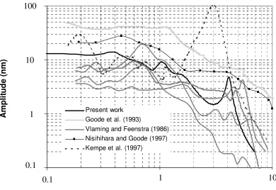
[image:22.612.135.419.348.556.2]Fig. 6. Amplitude of umbo displacement vs. frequency for an acoustic stimulus of 80 dB SPL. The experimental calculations of umbo displacement of Vlaming and Feenstra (1986), Nisihiharea and Goode (1997), Kempe et al. (1997) and Goode et al. (1993) are compared to the finite element predictions of this study.
1.00E-10 1.00E-09 1.00E-08 1.00E-07
100 1000 10000
Frequency (Hz) A m p li tu d e ( m ) Present work Goode et al. (1993)
Vlaming and Feenstra (1986) Nisihihara and Goode (1997) Kempe et al. (1997)
100 10 1 0.1 A m p li tu d e ( n m )
0.1
1
10
[image:23.612.109.499.74.342.2]Fig. 7. Finite element predictions for the displacement amplitude of (a) the umbo and (b) the stapedial footplate vs. frequency for the normal middle ear, the middle ear reconstructed with an Xomed PORP and the middle ear reconstructed with a Kurz PORP. 0.01 0.1 1 10 100
0.1 1 10
Frequency (kHz) A m p li tu d e ( n m ) Kurz PORP Xomed PORP NORMAL 0.01 0.1 1 10 100
0.1 1 10
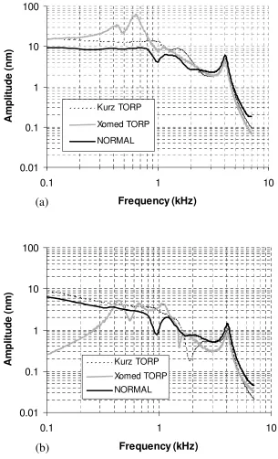
[image:24.612.132.446.98.598.2]Fig. 8 Finite element predictions for the displacement amplitude of (a) the umbo and (b) the stapedial footplate vs. frequency for the normal middle ear, the middle ear reconstructed with an Xomed TORP and the middle ear reconstructed with a Kurz TORP. 0.01 0.1 1 10 100
0.1 1 10
Frequency (kHz) A m p li tu d e ( n m ) Kurz TORP Xomed TORP NORMAL 0.01 0.1 1 10 100
0.1 1 10
[image:25.612.143.448.81.583.2]Fig. 9. Finite element predictions for the displacement amplitude of (a) the umbo and (b) the stapedial footplate vs. frequency for the normal middle ear and the middle ear reconstructed with a Kurz TORP placed onto the tympanic membrane in a postero-superior location.
0.1 1 10 100
0.1 1 10
Frequency (kHz) A m p li tu d e ( n m ) Kurz TORP Large Angle Normal 0.01 0.1 1 10 100
0.1 1 10
Fig. 10. Finite element predictions for the amplitude of displacement of the stapedial footplate vs. frequency for the middle ear reconstructed with a Kurz TORP placed onto the manubrium of the malleus and directly onto the tympanc membrane. (Note: In the prediction of footplate displacement for a prosthesis placed onto the tympanic membrane, there is a large angle between the malleus and the footplate.)
0.01 0.1 1 10 100
0.1 1 10
Frequency (kHz)
A
m
p
li
tu
d
e
(
n
m
)
Tympanic membrane
[image:27.612.124.456.94.313.2]Fig. 11. (a) The impedances of the middle ear vs. frequency for the normal middle ear and the middle ear reconstructed with a prosthesis modeled with a spring and mass element of varying mass and stiffness (impedance calculated by dividing the pressure at the umbo by the velocity). (b) A comparison of the amplitude of displacement of the stapedial footplate vs. frequency.
1. Ossicles
2. M = 15.4 mg; k = 1000 N/m 3. M = 8 mg; k = 1000 N/m 4. M = 27.4 mg; k = 750 N/m 5. M = 8 mg; k = 500 N/m
0.01 0.1 1 10 100
0.1 1 10
Frequency (kHz) A m p li tu d e ( n m ) 1 2 3 4 5
(b)
(a)
4 5 2 3 1 1.E+02 1.E+03 1.E+04 1.E+05 1.E+060.1 1 10
[image:28.612.143.419.78.549.2]