Engineer Manual
1110-2-4205
Washington, DC 20314-1000
30 June 1995
Engineering and Design
HYDROELECTRIC POWER PLANTS
MECHANICAL DESIGN
Distribution Restriction Statement
Approved for public release; distribution is
CECW-EE
Washington, DC 20314-1000
Manual
No. 1110-2-4205 30 June 1995
Engineering and Design
HYDROELECTRIC POWER PLANTS
MECHANICAL DESIGN
1. Purpose. The purpose of this manual is to provide guidance and criteria pertinent to the design and selection of hydroelectric power plant mechanical equipment and systems.
2. Applicability. This manual is applicable to all HQUSACE elements, major subordinate commands, districts, laboratories, and separate field operating activities having responsibility for civil works projects.
3. General. This manual discusses many items related to the planning and design of powerhouse mechanical equipment and systems. It is not intended as a comprehensive, step-by-step solution to powerhouse mechanical design, but as an experience-oriented guide and a basis for resolving differences of opinion among competent engineers at all levels.
FOR THE COMMANDER:
CECW-EE
Washington, DC 20314-1000
Manual
No. 1110-2-4205 30 June 1995
Engineering and Design
HYDROELECTRIC POWER PLANTS
MECHANICAL DESIGN
Table of Contents
Subject Paragraph Page Subject Paragraph Page
Chapter 1 Introduction
Purpose . . . 1-1 1-1 Applicability . . . 1-2 1-1 References . . . 1-3 1-1 Limitations . . . 1-4 1-1 Contents . . . 1-5 1-1 Design Procedures . . . 1-6 1-1 Other Design Information . . . 1-7 1-2 Deviations . . . 1-8 1-2 General Design Practices . . . 1-9 1-2 Safety Provisions . . . 1-10 1-2
Chapter 2
Turbines and Pump Turbines
General . . . 2-1 2-1 Francis-Type Turbines . . . 2-2 2-1 Francis-Type Pump Turbines . . . 2-3 2-3 Kaplan-Type Turbines . . . 2-4 2-4
Chapter 3
Generators and Motor-Generators
General . . . 3-1 3-1 Turbine Considerations . . . 3-2 3-1 Handling Provisions . . . 3-3 3-1 Service Systems . . . 3-4 3-1
Chapter 4 Governors
General . . . 4-1 4-1 Considerations . . . 4-2 4-1
Chapter 5
Penstock Shutoff Valves at the Powerhouse
General . . . 5-1 5-1
Valve Requirement . . . 5-2 5-1 Valve Selection . . . 5-3 5-1
Chapter 6
Cranes and Hoists
General . . . 6-1 6-1 Cranes . . . 6-2 6-1 Crane Lifting Accessories . . . . 6-3 6-6 Hoists . . . 6-4 6-8
Chapter 7 Elevators
General . . . 7-1 7-1 Justification . . . 7-2 7-1 Location . . . 7-3 7-1 Size . . . 7-4 7-1 Type . . . 7-5 7-2 Speed . . . 7-6 7-2 Control . . . 7-7 7-2 Design . . . 7-8 7-2 Procurement . . . 7-9 7-2
Chapter 8
Engine-Generator Set
General . . . 8-1 8-1 Location . . . 8-2 8-1 Engine . . . 8-3 8-1 Exhaust Provisions . . . 8-4 8-1 Cooling . . . 8-5 8-2 Fuel System . . . 8-6 8-2 Installation . . . 8-7 8-2
Chapter 9
Maintenance Shop
Subject Paragraph Page Subject Paragraph Page
Equipment Selection . . . 9-3 9-1 Shop Layout . . . 9-4 9-2 Drawing . . . 9-5 9-2
Chapter 10
Water Supply Systems
General . . . 10-1 10-1 Generator and Turbine Cooling
Water System . . . 10-2 10-1 Transformer Cooling Water . . . 10-3 10-2 Fire Protection Water . . . 10-4 10-3 Potable Water System . . . 10-5 10-3 Raw Water System . . . 10-6 10-5
Chapter 11
Unwatering and Drainage System
General . . . 11-1 11-1 Unwatering System . . . 11-2 11-1 Drainage System . . . 11-3 11-3 Equalizing (Filling) . . . 11-4 11-6 Venting . . . 11-5 11-7
Chapter 12 Oil Systems
General . . . 12-1 12-1 System Requirements . . . 12-2 12-1 Oil Storage Room . . . 12-3 12-1 Oil Storage Tanks . . . 12-4 12-1 Pumps . . . 12-5 12-2 Oil Piping . . . 12-6 12-2 Oil Purifiers . . . 12-7 12-3 Alternate Systems . . . 12-8 12-3
Chapter 13
Compressed Air Systems
General . . . 13-1 13-1 Service Air System . . . 13-2 13-1 Brake Air System . . . 13-3 13-3 Governor Air System . . . 13-4 13-3
Chapter 15
Fire Protection Systems
General . . . 15-1 15-1 Oil Storage and
Purification Rooms . . . 15-2 15-1 Paint and Flammable Liquid
Storage Room . . . 15-3 15-1 Generators . . . 15-4 15-2 Motors . . . 15-5 15-2 Transformers . . . 15-6 15-2 Portable Fire Extinguishers . . . 15-7 15-3 Detections . . . 15-8 15-3 Isolation and Smoke Control . . 15-9 15-3 Fire Hose . . . 15-10 15-3
Chapter 16
Piezometers, Flow Meters, and Level Gauges
General . . . 16-1 16-1 Turbine Piezometers . . . 16-2 16-1 Miscellaneous Piezometers . . . . 16-3 16-2 Water Level Gauges . . . 16-4 16-2
Chapter 17 Piping
General . . . 17-1 17-1 Design Considerations . . . 17-2 17-1
Chapter 18
Heating, Ventilating, and Air Conditioning System
General . . . 18-1 18-1 Design Conditions . . . 18-2 18-1 Design . . . 18-3 18-2 Design Memorandum . . . 18-4 18-5
Chapter 19
Chapter 1
Introduction
1-1. Purpose
This manual provides information and criteria pertinent to the design and selection of hydroelectric power plant mechanical equipment and systems for new and rehabilita-tion projects. It is applicable to all such work within the U.S. Army Corps of Engineers responsibility.
1-2. Applicability
This manual is applicable to all HQUSACE elements, major subordinate commands, districts, laboratories, and separate field operating activities having responsibility for civil works projects.
1-3. References
Required and related publications are listed in Appendix A.
1-4. Limitations
a. Information covered in other manuals. The selec-tion, procurement, and specification of certain major mechanical equipment are covered in other existing or pending engineer manual and guide specifications, includ-ing turbines, pump-turbines, governors, and mechanical aspects of generators. Information contained herein perti-nent to such equipment is principally to aid in preparation of contract specifications based on the guide specification.
b. Detail design. This manual is not intended as a comprehensive, step-by-step solution to powerhouse mechanical design nor as a substitute for sound engineer-ing resourcefulness and judgment. Used as a “guide post,” not a “hitching post,” it provides experience-oriented guidance and a basis for resolving differences of opinion among the competent engineers at all levels.
c. Material generally available. The manual stresses information that is of particular applicability to powerhouses. Other material useful in powerhouse mechanical design which is readily available in standard publications is not generally repeated or referenced herein.
1-5. Contents
This manual is divided into 18 chapters, each covering one or more closely related items of powerhouse
mechanical equipment or system, a Chapter 19 on corro-sion mitigation, and two appendices. Equipment and systems where the detail design responsibility is normally delegated to the contractor, or where other engineering manuals are applicable, are covered with the emphasis on application, selection, and specification aspects. Equip-ment and systems where the detail design is normally a Corps of Engineers office function are covered in greater detail or referenced to applicable standard design codes or handbooks. Appendix A lists references to other material such as guide specifications, codes, industry standards, and other engineering manuals provided throughout this manual as applicable. Appendix B contains specification excerpts, typical system schematics, and drawings of equipment and details typical of powerhouses and other information not readily available from commonly known sources.
1-6. Design Procedures
a. Standard procedures. Department of the Army Civil Works Guide Specification CE-4000 provides the standard procedure for development of a powerhouse design. These procedures include a Preliminary Design Report, Feature Design Memoranda, an Analysis of Design, Contract Drawings, Specifications, and Cost Esti-mates. CE-4000 prescribes the timing, preparation, and approval procedure for this material and also references other applicable manuals and guides. While the format and instructions of CE-4000 imply applicability only to Architect-Engineer design contracts, the design procedures noted therein should be followed by all district or division offices performing powerhouse mechanical design. Fund-ing problems, fluctuations in planned manpower, and conflicts in design scheduling will tend to alter the pre-scribed order of procedures. However, all stated require-ments should be met unless prior approval of an alternate procedure is obtained from higher authority.
b. Additional procedures.
(1) Shop drawing review. The checking of contrac-tor shop drawings and other material for adequacy and compliance with specification requirements is normally assigned to the engineers who prepared the design.
1-7. Other Design Information
a. Sources. Information which may be helpful in design is available from many sources other than pre-scribed Corps of Engineers material and standard hand-books. Design memorandums and drawings from other projects, manufacturers’ catalog information, sales engi-neers, project operation and maintenance reports, field inspectors, operation and maintenance personnel, and the powerhouse electrical and structural design personnel are all valuable and readily available sources. Good com-munication with other Corps of Engineer District and Division offices can often expedite information on a par-ticular problem.
b. Evaluation. Evaluation of available information should be approached with skepticism and judgment. Relying on previous satisfactory designs requires that the design conditions and requirements be carefully compared for applicability. The obtainment and evaluation of infor-mation from field sources is improved by the personal acquaintanceships and observations resulting from design engineer visits to under construction and operating plants as well as supplier plants. Office policies should permit and encourage these visits.
1-8. Deviations
Considerable flexibility in design is available to the design engineer within the manual provisions. It is recog-nized that new applications and techniques may justify deviations from the stated provisions. In such circum-stances, advance consultation with higher authority is suggested.
1-9. General Design Practices
a. Factors during fabrication. Design should reflect the quality of materials, workmanship, and general quality control normally experienced. The engineer will not have absolute control over these factors during fabrication but
d. Backup requirements. Backup requirements should be evaluated both on the probability and effect of malfunction. Frequent, minor malfunctions can be expen-sive; a major-once-in-a-hundred year malfunction can be catastrophic.
e. Reducing personnel. The continuing emphasis on reducing operation and maintenance personnel should be reflected in designs requiring frequent operation and maintenance.
f. Generous tolerances. Tolerances and fits should be generous as practicable. Precision workmanship is expensive and undependable to obtain.
g. Design computations. The design computations should include the sources of all existing designs fol-lowed, sources of data, a record of alternate designs investigated, actual design computations used, and planned operating procedures. In providing design refer-ences, particularly where more than one reference is listed, a specific reference to the particular source is essential. A general listing of references potentially appli-cable to a system or item of equipment is of little value for review or record purposes. Providing specific refer-ences is essential in design memorandums as well as design computations in general.
h. Environmental quality. Incorporating environ-mental quality in project design is essential. Opportuni-ties for enhancement through design will be vigorously sought. Specific ecological considerations in hydropower mechanical design include, but are not limited to, the use of environmentally safe lubricants, actions to preserve or enhance the survivability of fish (fish survival rate versus turbine efficiency), and actions to maintain or enhance water quality (location of the water intakes).
dis-Occupation Safety and Health Administration (generally referred to as OSHA Standards) are to be considered minimum requirements in Corps of Engineers design (see EM 385-1-1). Areas of particular concern, to mechanical design, are noise levels, personnel access provisions,
Chapter 2
Turbines and Pump Turbines
2-1. General
Mechanical design responsibilities in connection with turbines and pump turbines include selection of type of unit, power rating, operating characteristics and number of units, preparing contract specifications, checking contrac-tors drawings, and coordinating related powerhouse facili-ties including generator, governor, air, water, and oil systems, handling provisions, and structural requirements. The guidance for turbine and pump-turbine selection is included in ETL 1110-2-317. Design of turbines is a contractor responsibility and is included under the supply contract used for turbine procurement. Coverage in this chapter is generally limited to considerations in prepara-tion and compleprepara-tion of the project specificaprepara-tions. Tur-bines are a major and critical item in powerhouses and warrant maximum effort to assure practical, well-coordi-nated specifications with reasonable assurance of respon-sive bidding. In addition to the guidance referenced above, the specifications should reflect Corps experience with previous similar units and preliminary exchange of information and proposals with potential suppliers.
2-2. Francis-Type Turbines
a. Scheduling. Drawing and data submittal times, commencement and completion of work, delivery schedules, and installation work scheduling should be coordinated with general project scheduling and turbine manufacturers. Suppliers of hydraulic turbines are lim-ited. Therefore, early contact with potential suppliers is advisable to determine their capability for bidding to the proposed dates and to assure a competitive bidding response.
b. Stainless steel runners. Stainless steel runners
warranted since required areas will be determined after runner design is complete and model tested, and payment will be adjusted accordingly. The final determination of required area made by the contractor is usually accepted since it would be a factor in the cavitation guarantee.
d. Shaft diameter. The minimum shaft diameter for new construction should be computed on the basis of 38,000 kPa (5,500 psi) maximum shear stress and unity power factor. On projects where the units are being uprated the limit should be set at 41,000 kPa (6,000 psi). The maximum torsional stress should be calculated using the Mohr’s circle which combines the following stresses: stress due to the weight of all rotating parts carried by the shaft; stress created by the maximum steady-state operat-ing hydraulic thrust; and the stress produced by the maxi-mum torque the turbine would be allowed to produce, normally the maximum continuous duty rating (MCDR) at a power factor (PF) of 1.0.
e. Shaft length. The estimated elevation of the tur-bine shaft coupling should be set to realize a minimum required height of powerhouse walls, taking in to account required handling clearances of the generator rotor and shaft and the turbine rotor and shaft.
f. Shaft inspection hole. The minimum diameter of the axial hole through the turbine shaft for inspection purposes is about 100 mm (4 in.). Holes which have diameters of 150-200 mm (6-8 in.) are normally specified on the larger shafts where the reduction in strength would be insignificant. The larger holes expedite inspection and remove additional core material prone to shrinkage cavities.
h. Guide bearing oil pumps. Pressurized lubrication systems are sometimes used for guide bearings, and the guide specification includes the pump requirements. However, self-lubricating bearings are practicable and are preferred for reliability and to reduce the connected DC load. An oil sump drainage pump is required when it is not practicable to drain the sump to the oil storage room by gravity. Capacity should usually be based on draining the sump in 3-4 hr. The installed pump option is pre-ferred over a portable pump for convenience and savings in operational manhours.
i. Stay ring.
(1) Internal pressure. The stay ring should be designed for an internal pressure based on maximum pool head plus water hammer.
(2) Grout holes. Holes required for placing of grout under the stay ring are normally 50 mm (2 in.) in diam-eter. A diameter of 20 mm (3/4 in.) is satisfactory for vent holes.
j. Spiral case and spiral case extension. The spec-ific requirement is dependent on the need for a field hydrostatic test, the need for a valve at the end of the penstock, and the method of connecting spiral case exten-sion to the penstock or penstock valve.
(1) Hydrostatic test. Standard practice is to require a field hydrostatic test on all units requiring field welding. Elimination of field welding is practical only with very small cases permitting full shop assembly and shipping. The test should be specified at 150 percent of design head including water hammer. When a hydrostatic test is spec-ified, the alternative of magnetic particle inspection for circumferential shop and field welded joints may be used. A field hydrostatic test will also require the alternative of providing a test pump and sealing off devices at the stay ring opening and inlet end of the spiral case extension. Also, when a field hydrostatic test is performed, the embedment of the case is performed while pressurized and the test pump is used to maintain design pressure in the case. The relief valve specified should be capable of being set at both the design pressure and test pressure. The pressure alarm should be actuated at a 68.9-kPa (10-psi) drop below design pressure. If circumstances are such that embedment with pressurized spiral case is impracticable, a mastic blanket covering the spiral case and extension is usually required to minimize the trans-mittal of operating head load to the concrete. An alterna-tive requiring an additional 76-mm (3-in.) length of spiral
case extension is necessary for cutting and finishing when removing a test head.
(2) Penstockk valve. Chapter 5 discusses factors relating to the requirements for penstock valves. Valves may be of either the butterfly or spherical type. The pen-stock extension-to-valve connection options are not influ-enced by the type of valve. Valves may be procured under the turbine contract or provided by a separate sup-ply contract. A separate schedule should be provided when the valves are included so that award can be made by schedule or by a combination of schedules to eliminate undesirable effects on competitive bidding.
(3) Connection to spiral case extension. The choice of a flexible sleeve-type coupling or a welded joint for connecting the spiral case extension to the penstock valve or penstock depends primarily on structural consider-ations. These considerations involve the most practicable point at which to take the closed valve reaction and the probability of differential settlement or other structural factors affecting alignment of the penstock and spiral case extension.
(a) With penstock valve. Where a penstock valve is used, the reaction of the closed valve is generally taken by the penstock and a flexible coupling provided to con-nect the valve to the spiral case extension. This connec-tion requires a straight secconnec-tion of penstock extension with tolerances to meet the coupling requirements and long enough to permit assembly and disassembly. Guide spec-ification options are included for obtaining the straight section. A welded connection for valve-to-spiral case extension is satisfactory with closed valve reaction taken by the penstock and structural and foundation conditions indicating no potential misalignment problems.
(b) Without penstock valve. A welded connection should generally be used unless structural and foundation conditions indicate a possibility of misalignment prob-lems. Where a flexible coupling is indicated, the straight penstock section will be required as with the valve-type installation.
generator and turbine bidders, requirements at existing projects, crossover requirements, and the proposed power-house piping system. A connection is not required where a tailwater pumped supply is justified. If piping and valve location considerations warrant, the supply connec-tion may be specified on the spiral case rather than on the spiral case extension.
(5) Drain. The spiral case-extension drain should be sized in accordance with the considerations noted in paragraph 11-2b(3).
k. Runner wearing rings. Wearing rings on the run-ner are not normally specified as operating experience has indicated little or no requirement for replacement. Sta-tionary wearing rings above and below the runner should be specified.
l. Facing plates and wicket gate seals. Facing plates above and below the wicket gates are not required when gate seals are provided. Gate seals are usually justified. Rubber seals without facings are generally satis-factory to about 91 m (300 ft) of head. Bronze or stain-less facings should be required over 91 m (300 ft) of head.
m. Air depression connection. Where an air depres-sion system for depressing the draft water below the runner is planned, or is a future probability, a flanged connection in the head cover should be provided. Consid-erations pertinent to sizing the connection are discussed in paragraph 13-5.
n. Wicket gate shear pin detection. A pneumatic system for detecting a broken shear pin is not normally installed until operating experience indicates a need. The tapped hole option should be included in the specification as the cost is minimal.
o. Wicket gate servomotor pressure. Nominal sys-tem operating pressures (high end of operating range)
indicates the cost of alternate pressure systems to be approximately the same, the lower pressure system should be specified. System piping, fittings, and packing appro-priate for the operating pressure should be specified. A standard pressure should be specified (refer to Guide Specification CW-11290).
p. Gate locking device. A manual device is satisfac-tory for the open gate position. An automatic device for the closed gate position should be provided for all units to permit automatic locking on unit shutdown.
q. Pit liner. The minimum elevation of top of pit liner should be specified to be approximately 0.6 m (2 ft) above the servomotor elevation. Minimum plate thickness should be 13 mm (1/2 in.) to permit tapped holes for the mounting of piping and equipment. One personnel entrance to the turbine pit is sufficient unless safety regu-lations would require an additional access for emergency escape.
r. Draft tube liner. The minimum draft tube liner thickness is usually specified at 16-19 mm (5/8-3/4 in.) depending on the draft tube size. The liner should extend down to protect concrete from water velocities over 9 m/s (30 fps) and a minimum of 0.9 m (3 ft) below the main door.
restric-2-4. Kaplan-Type Turbines
Items listed in paragraph 2-2 are generally applicable to Kaplan units also. Additional considerations pertinent to Kaplan units are as follows:
a. Blade servomotor location. A location requiring removal and disassembly of the runner to effect repair or replacement of the servomotor is not recommended. This would normally rule out an upper hub location as an acceptable option. Location of the blade servomotor is a factor in selecting the governor operating pressure. When the servomotor is located in the shaft, higher pressures will permit a reasonable shaft and flange diameter at the servomotor. Locating the servomotor in the runner cone below the blades is an acceptable alternative to the shaft location.
Chapter 3
Generators and Motor-Generators
3-1. General
Design of generators and motor-generators is specified as a contractor responsibility. Design requirements and specifications are the responsibilities of electrical disci-pline within the Corps of Engineers (see EM 1110-2-3006 for guidance). Guide Specification CW-16210 provides the basis for preparation of contract specifications. Mechanical design includes the following responsibilities: coordination of turbine and generator mechanical charac-teristics; required generator handling facilities; and oil, air, carbon dioxide (CO2), and water service connections to
the generator. Design considerations for the generator as related to the turbines, cranes, and piping systems are covered under the respective chapters of this manual. Discussion in this chapter pertains to mechanical consider-ations in completing generator guide specificconsider-ations.
3-2. Turbine Considerations
Powerhouse scheduling normally requires contracting of the turbines prior to preparation of generator specifica-tions. This permits the required turbine data for the gen-erator specification to be obtained from the turbine specification, the turbine bid data, and the turbine model test. Preadvertising correspondence with turbine and generator suppliers should provide verification that the turbine related stipulations in the generator specification are practicable. The required flywheel effect of rotating generator parts must be computed on the basis of all related factors. This includes turbine characteristics as well as penstock, generator, governor, and power system characteristics. Maximum speed rise and pressure rise upon loss of generator load are normally the critical mechanical factors. Turbines and generators are specified to withstand stresses due to runaway speeds; however, the
3-3. Handling Provisions
The powerhouse crane is normally sized to handle the generator parts, and no size or weight restrictions should be included in the generator specification. Certain power-houses may justify two (2) cranes coupled together for handling the heavier parts. These should also be designed to meet the generator requirements. Exceptions to this policy may be required where a new unit is being pro-vided in an existing crane equipped powerhouse, or where scheduling revisions require a crane to be under contract before a generator contract is awarded. In either case, the appropriate crane limitation should be included in the generator specification. Ratings for a crane procured before generator data are available should be based on prebid exchange of information with generator suppliers. Crane design guidance is covered in Chapter 6 of this manual. For existing powerhouses, a crane clearance dia-gram, powerhouse access limitations, and other applicable physical limitations should be included in the generator specifications.
3-4. Service Systems
c. Carbon dioxide systems. The CO2 piping
termi-nations are generally as noted above in paragraph 3-4a for oil piping. In powerhouses where the CO2 powerhouse
headers are routed above the generator floor elevation, it may be preferable to route the connecting lines overhead to enter the generator housing near the top. Para-graph 15-4 provides guidance on generator CO2systems.
d. Water. Powerhouse cooling water supply and dis-charge lines serving the generator air coolers and bearing oil coolers are normally terminated in the lower generator housing. Cooling water head and temperature consider-ations and test pressures should be as discussed in para-graph 2-2g for turbine bearing coolers. Related comments
Chapter 4
Governors
4-1. General
The design of governors for turbines and pump-turbines is specified as a responsibility of the governor manufacturer. In general, the governor operating requirements and char-acteristics will be determined from the electrical, mechan-ical, and hydraulic characteristics of the generator, turbine, and penstock. Guide Specification CW-16252 provides the basis for preparing specifications. EM 1110-2-3006 provides guidance for the electrical and electronic controls of the governor. Coverage in this chapter includes considerations pertinent to selecting the guide specifications mechanical options.
4-2. Considerations
a. System pressures. The nominal pressure of gov-ernor-servomotor systems is selected from a series of standard pressures ranging from 2,067-6,890 kPa (300-1,000 psi). Turbine requirements will usually indicate the desirable nominal pressure (refer to paragraph 2-2o). Since turbine contracts are normally scheduled in advance of governor contracts, the nominal pressure will have been determined before the governor specification is pre-pared. However, it is important to exchange information with potential governor suppliers during preparation of the turbine specification. The working pressure range should be appropriate for the nominal system pressure as indi-cated in the guide specification. The differential pressure across gate servomotor ports (and oil head ports of Kap-lan units) is assumed 80 percent of the minimum working pressure range for figuring servomotor capacity. This assumed value allows for piping and valve losses and requires that the governor and turbine contractors cooper-ate to limit the pressure drop in the system accordingly. System design pressure should be at the pressure tank
surface temperature of the oil heater does not cause any chemical change of the oil, such as chemical breakdown.
c. Pressure tank.
(1) Location. The powerhouse equipment layout should provide the pressure tank location(s) with the shortest and most direct lines practicable from the tank to the actuator and servomotors in order to minimize pres-sure losses.
(2) Tank design and pressure. The tank and safety valve shall be designed in accordance with the latest version of the American Society of Mechanical Engineers (ASME) “Boiler and Pressure Vessel Code.” The tank design pressure should be a minimum of 115 percent of the maximum system operating pressure. This will allow for variations in the pump stop switch and oil pump pres-sure relief valve and safety valve blowdown prespres-sure. A pilot-operated ASME safety valve should be used which has a 98 percent cracking pressure and a 4 percent blow-down. The safety valve setting should never exceed the stamped tank pressure rating but should be equal to or less than the stamped tank pressure rating. An example is as follows:
Stamped Tank Pressure . . . 4,795 kPa (696 psi) Stamped Safety Valve Setting . . . 4,168 kPa
(605 psi) Safety Valve Cracking Pressure . . . 4,086 kPa
(593 psi) Safety Valve Blowdown Pressure . . . 3,996 kPa
(580 psi) Oil Pump Pressure Relief Setting . . . 3,962 kPa
(575 psi) Governor Oil Pump High-Pressure Stop Switch
(Maximum system operating pressure) . . . 3,790 kPa (550 psi)
In addition, pressure tank high-level and sump tank low-level contacts are used for pump control to stop the pump and lock it out in case of pump unloader valve failure.
d. Distributing valve adjustment. The required setting for the wicket gate opening or closing rate is dependent on the design for maximum unit overspeed and the water hammer design stresses in the penstock and turbine. The timing usually stated in the specifications is between 8 and 20 sec. For turbine blade adjustment, a rapid response is not required and can impose undesirable stresses in the blade operating mechanism. Then the timing usually stated in the specification is between 20 and 60 sec.
e. Maximum runaway speed. The maximum run-away speed to be specified should be based on the turbine model test results.
Chapter 5
Penstock Shutoff Valves at the
Powerhouse
5-1. General
Butterfly and spherical valves are typically used at Corps of Engineers projects when shutoff capability is required at the powerhouse end of the penstock. Mechanical design responsibilities for these valves include the deter-mination of need, selection of type and size, selection of auxiliary equipment, coordination of location and space requirements, preparation of contract drawings and speci-fications, review of contractor submittals, and preparation of instruction manuals.
5-2. Valve Requirement
A shutoff valve may be required at the powerhouse end of penstocks for either turbine or pump-turbine units. The purpose of this valve is to provide emergency shutoff in case of flooding-type failure or loss of speed control, reduction of leakage through wicket gates, and for mainte-nance of the turbine. However, shutoff provisions are usually required at the intake of each penstock. As a result, a shutoff valve at the unit may not be required. Several factors should be considered when deciding the need for a shutoff valve at the unit. The factors include but are not limited to the following:
a. Type of shutoff at the penstock intake. A quick closing shutoff at the penstock intake, operable under emergency conditions, may be an alternative to a shutoff at the powerhouse. Where maintenance and emergency shutdown can be satisfied with the intake shutoff, the requirement for powerhouse valves can seldom be justified.
b. Length of penstock. A long section of penstock
d. Multiple units per penstock. Operational and maintenance flexibility will normally require a separate shutoff valve for each unit. Generally, maintenance requirements alone will justify powerhouse shutoff valves for multiple unit penstocks.
e. Type of wicket gate seal. A tight seal reduces leakage losses. However, deterioration of the seal with time should be considered when determining the effects of leakage.
Evaluation of the factors should consider their effects on maintenance, emergency operations, and costs. The fac-tors considered and basis of determination should be included in the mechanical design memorandum.
5-3. Valve Selection
Butterfly and spherical valves are generally available as a catalog item for heads up to 183 m (600 ft) and in sizes up to 2.4 m (8 ft). Valves for conditions exceeding these limits are typically designed for the specific application. Factors to be considered include initial cost, maintenance, head loss through valve, and requirements for transition sections.
a. Spherical valves.
applicable. The installation may require the valve to withstand heads from either direction when closed. If the valve is to be used for emergency closure, the operator should be capable of closing the valve in 2-5 min as practicable for the size.
(b) Valve body. The valve body should be made in halves of fabricated or cast steel, properly annealed, and adequately designed to resist the hydraulic forces acting directly on the body and those resulting from the thrust for any position of the valve rotor. Integrally cast or forged (if fabricated) steel flanges, suitably machined, should be provided for bolting the body pieces together and circumferential flanges for bolting to the pipe extensions.
(c) Rotor. The valve rotor should be made in one piece of annealed cast or fabricated steel and should ade-quately resist the bending and shearing load resulting from the hydraulic and operating forces.
(d) Seals. Retractable seal rings should be provided to permit separation of the sealing surfaces during rotation of the rotor. Sealing surfaces should be corrosion resis-tant and of different composition and hardness to mini-mize galling. One seal of 300 series stainless and one of 400 series stainless will perform satisfactorily in most waters. However, the source water should be checked for unusual corrosiveness. Then the materials should be specified accordingly. Both sealing surfaces should be removable for replacement. The retractable seal ring should normally be oil-hydraulically operated. Both upstream and downstream seals may be justified to allow more flexibility in scheduling of seal replacement.
(e) Trunnion bearings. Trunnion bearing with renew-able self-lubricating bronze sleeves and bronze thrust washers should be provided. Bearing housings should be integral to the body casting. A means of adjusting and centering the rotor should be provided. Pressure relief for leakage water through the gland should be verified.
(f) Bypass. A bypass valve permitting equalized pressure on both sides of the spherical valve before open-ing should be provided. The bypass is normally motor operated for automatic control.
(g) Valve operator. A double-acting hydraulic cylin-der operator should be provided for opening and closing the valve. The operator should be capable of closing the valve at maximum pool head and maximum discharge. Opening capability should be at balanced head conditions. The operator should also be suitable for continuous
pressurization to hold the rotor in either the fully closed or open position. All valve and operator components subject to loading from operator action should be designed for the maximum hydraulic cylinder forces.
(h) Operator control. The type of control should be appropriate for normal unit operation and emergency shutdown requirements. Pumps are normally on pressure switch control and are protected with relief or unloading valves. Cylinder action is normally controlled with motor-operated tight sealing four-way valves and pres-sure-compensated flow control valves set to obtain the required opening and closing times. Spool-type control valves are not suitable for extended pressurizing periods in one direction. Impurities tend to filter out in the spool clearances causing sticking and failure to operate. Gauges, isolating valves, filters, alarms, control panels, and limit switches should be provided as applicable.
(i) Pipe extensions. Pipe extensions for connecting the valve to the penstock and spiral case extension are generally procured with the valve. The extensions should be designed on the same basis as the penstock. One end of each extension should be provided with a flange to connect to the valve flange. The other end of each exten-sion should be prepared for a welded and or sleeve-type connection, as required. When required, the sleeve cou-plings are normally procured with the extensions.
(3) Safety provisions.
(a) A lockable, mechanical latch should be provided for securing the valve in the closed position. The latch should be capable of withstanding any opening force obtainable from the hydraulic operator to protect workmen from accidental opening of the valve.
(b) A mechanical hydraulic hand pump and manu-ally operable control valves should be provided for man-ual operation of the valve in either direction.
(c) The valve operating cylinder should be cushioned to prevent damage due to the valve slamming in the event oil pressure is lost.
(d) Additional flow control valves should be pro-vided in the hydraulic circuit at the cylinders. These valves should limit the flow to 125 percent of normal closure flow if line pressure is lost.
of which is capable of performing a normal opening or emergency closing.
(f) Accumulators should be provided in the hydraulic system with capacity sufficient to fully close or open all spherical valves on the system with both pumps inopera-tive after the low system pressure alarm has been activated.
(g) All parts and components subject to loading from operation of the hydraulic operator should be designed for maximum stress of 75 percent of yield point with a maxi-mum attainable pressure in the cylinder. Maximum attainable pressure should be assumed as either pump shutoff pressure or maximum setting of the relief valve sized for maximum pump delivery.
(h) Valve bodies and rotors should be hydrostatically tested at 150 percent of design head in both directions and with rotors open and closed.
(4) Design. Design of spherical valves and operators should be specified as a contractor responsibility. How-ever, the valves are a critical item in obtaining and main-taining satisfactory unit operation. Therefore, the specifications should require equipment of a design proven in service. Standard catalog equipment is pre-ferred when available. Where a size and head rating not previously in use is required, the specifications should require the bidder to have experience in designing and manufacturing similar valves of the approximate size and head rating.
b. Butterfly valves.
(1) General. Butterfly valves consist of a valve body, valve disc, bearings, and operator. Head loss through a butterfly valve is higher than for a spherical valve. Losses are higher for lenticular-type disks versus the open truss-type disc. Head loss may justify an oversize valve with suitable transition sections. Some leakage is
charac-(c) Disc. The valve disc should be of cast or fabri-cated construction and either lenticular or open truss design. Design stresses should not exceed 50 percent of yield point or 25 percent of ultimate at design head. Fab-ricated designs should be stress relieved before machin-ing. Disc design should provide for wedge sealing action with the disc at less than 90 deg to valve axis, and the disc should have positive overtravel limits. The limit may be provided by mechanical stops or by bottoming of oper-ator piston.
(d) Seals. Valve body and disc seals should be of corrosion resistant steel of different composition and hardness to minimize galling. Both seals should be replaceable without dismantling the valve, and the body seal should be adjustable from outside the valve. Suit-ability of the seal composition to resist corrosion in the penstock water should be verified by prior operating experience or chemical analysis. Seal design should not be compromised to allow a manufacturer’s standard design.
(e) Valve shaft. The valve shaft for lenticular discs should be one piece. Shafts for open truss-type discs may be bolted on. Corrosion resistant sleeves should be pro-vided at the packing boxes if noncorrosion resistance shafts are used.
(f) Bearings. Shaft bearings should be sleeve type, self-lubricated and should include adjustable thrust sur-faces for centering the disc.
(g) Bypass (see paragraph 5-3a(2)(f)).
(h) Valve operator (see paragraph 5-3a(2)(g)).
(i) Operator control (see paragraph 5-3a(2)(h)).
para-(4) Design. The design of butterfly valves and opera-tors should be specified as a contractor responsibility. However, the valves are a critical item in obtaining and maintaining satisfactory unit operation. Therefore, the specifications should require equipment of a design proven in service. Standard catalog equipment is
Chapter 6
Cranes and Hoists
6-1. General
a. General. Cranes and hoists are used in power-houses for operational functions and for maintenance and repair. The general hoisting functions involved are simi-lar for most powerhouses, but loadings, frequency of usage, powerhouse configuration, installed equipment, value of downtime, and availability of portable equipment can affect the optimum provisions for a particular project. Normally, initial planning should be on the basis of an existing project with similar requirements, but careful consideration of the variables should precede final selec-tion of cranes and hoists.
b. Terminology. “Cranes” and “Hoists” are some-what interchangeable terminology since the actual lifting mechanism of a crane is commonly referred to as a hoist. For purposes of coverage in this chapter, “Hoists” will be considered as separate items of equipment that include installations where the hoist machine is fixed and there is no controlled lateral movement of the hook(s) or lifting block(s). Other applications are covered under “Cranes.”
c. Emergency closure. For safety reasons, two dif-ferent closure methods to shutoff the water supply to the turbine are required. One method is considered to be the wicket gates. The other method shall be a penstock shut-off valve (refer to Chapter 5), or an intake gate lowered by a hoist. Fixed hoists at each intake gate slot are used to lower the intake gates in an emergency situation. Intake gantry cranes are not normally used to lower intake gates in an emergency because of the much slower response time and potential crane-capacity problems.
6-2. Cranes
(3) Intake gantry. A gantry-type crane serving intake gates, trashracks, bulkheads, fish screens, and mis-cellaneous items on the intake decks of powerhouses.
(4) Draft tube gantry. A gantry-type crane serving stop logs, bulkheads, and miscellaneous items on the tailrace deck of powerhouses.
(5) Mobile crane. A self-propelled, rubber-tired crane for general use, principally on intake or tailrace decks and miscellaneous nonpowerhouse project functions.
(6) Maintenance shop bridge crane. A maintenance shop bridge crane, usually a trolley-mounted electric hoist suspended from a single girder bridge, serving equipment in the maintenance shop.
(7) Floor crane. A light, portable crane with wheels for mobility on powerhouse and maintenance shop floor areas, normally manually being propelled.
(8) Monorail crane. A trolley-mounted, motorized or manual, hoist running on an I beam track for special applications.
(9) Jib crane. A wall or pillar-mounted, rotating bracket with an electric or manual hoist for specialized lifts with limited horizontal movement requirements.
b. Preliminary considerations. For each power-house, the following preliminary considerations should precede design and specification work on the individual cranes:
(1) Items handled. A preliminary listing of all major items to be handled by powerhouse cranes during con-struction, operation, maintenance, and repair should be prepared. The listing should include estimated weights, pickup and set down points, and the crane to be used.
(3) Coordination. The preparation of the listing of items to be handled and area layout drawings should include information exchanged with construction and operation divisions as well as other engineering responsi-bilities. All reasonable adjustments in equipment location to provide effective and economical crane service should be negotiated also.
(4) Miscellaneous preliminary considerations. Corro-sion mitigation is discussed in paragraph 19-2.
c. Engineering and design. Most engineering and detail design criteria for powerhouse cranes are covered in engineering manuals and guide specifications as refer-enced herein under the particular crane type. Final detail design and construction of cranes are responsibilities of the supplier as provided under the procurement contracts. The responsibility of the powerhouse design office is to obtain and coordinate all preliminary information noted in paragraph 6-2b; to determine requirements for each crane based on the preliminary information; to prepare crane clearance drawings based on sufficient design studies; to assure a practical and economical crane; to prepare speci-fications; and to review shop drawings, design computa-tions, and operating instruction manuals. Documentation of assumptions and reasons for selecting particular lifting procedures and equipment arrangements should be a part of the design records. The preliminary studies and coor-dination are important in obtaining the optimum crane for the required service, and shortcuts should not be made.
d. Bidder qualifications. Bidder qualifications are not normally an engineering responsibility, but in the case of powerhouse cranes, it is particularly important for the powerhouse mechanical designers to exert their influence in obtaining qualified contractors. Providing cranes ready for service on schedule is very important to avoid impact to overall powerhouse construction schedules. Contractors inexperienced in design and construction of cranes have caused costly delays and impacts to other construction work. Many times a two-step bidding process is prudent in order to obtain a quality product on schedule.
e. Powerhouse bridge cranes.
(1) General. General criteria and design procedures, along with data on existing cranes, are available in EM 1110-2-4203. Detail design criteria for indoor bridge cranes are covered in Guide Specification CW-14330. For outdoor powerhouses, the powerhouse crane will normally be a gantry type for which design criteria noted in Guide Specification CW-14340 should be used as indi-cated in paragraph 9 of EM 1110-2-4203. Coverage
herein is limited to additional general factors which enter into crane requirements and crane selection. The discus-sion is applicable particularly to powerhouses with con-ventional vertical units; however, most factors noted are also applicable to cranes servicing slant or bulb units. Some slant units may require two cranes, one upstream and one downstream, because of horizontal distance between generator and turbine. Special intermediate lift and handling facilities are usually involved with either slant- or bulb-type units. These special facilities should be determined and furnished by the generator and turbine contractors subject to the normal design office shop-draw-ing reviews.
(2) Number of cranes. The choice of providing one or two cranes is an important consideration in power-houses with several units or heavy capacity requirements. Factors entering into this determination are:
(a) Procurement cost. This cost considers one crane versus two.
(b) Powerhouse structural costs. A single crane may increase structural costs because of greater physical size, though generally only moderate additional cost is involved.
(c) Construction and erection advantages of two-crane availability. Two two-cranes will usually be more bene-ficial in long multiunit powerhouses and may have significant advantages where the construction schedule requires continued erection work after several units are in operation.
(d) Additional crane clearance. The necessity to provide two-crane lifting beam configuration will increase the roof height.
(e) Hook coverage limitations. Unusually large capacity single cranes result in greater floor areas not accessible to a lifting hook.
(f) Additional maintenance cost. Maintaining two cranes versus one does increase this cost.
(g) Value of unit downtime. Two cranes may expe-dite maintenance or repairs.
the considerations pertinent to the selection of one or two cranes.
(3) AC versus DC drive systems. Current technology of AC variable frequency drives enables them to have performance similar to a DC drive, and the cost is approximately the same. One advantage of the AC drive is reduced maintenance since induction motors do not have brushes as DC motors do. The guide specifications list several alternatives to be determined for each specific application.
(4) Crane capacity. EM 1110-2-4203 includes guid-ance for determining crane capacity. In applying the criteria the engineer should be aware that numerous fac-tors beyond engineering control tend to disrupt orderly scheduling, and it will frequently be necessary to prepare contract drawings and specifications for cranes before accurate final loads are determined. It is also sometimes necessary to firm up powerhouse structure design affected by crane capacity and clearances prior to final confirma-tion of lifting loads. In such cases, capacity should be based conservatively on estimated loads (to avoid later increases). Loadings due to planned or potential future units should also receive consideration in determining crane capacity and be included in the design computa-tions. It has been the Corps of Engineers practice to specify crane ratings that allow up to 10 percent overload for infrequent special heavy lifts such as the generator rotor when a preferred crane rating falls within this range. For cranes designed in accordance with Corps of Engi-neers guide specifications, this overload is well within the allowable stresses permitted by the Crane Manufacturers Association of America (CMAA) standards and is in accordance with ANSI standards and OSHA’S interpreta-tion of their regulainterpreta-tions.
(5) Appearance. Powerhouse bridge crane appearance should be consistent with the interior finish of the power-house. It is usually advisable to rely on the powerhouse architect for determination of an acceptable appearance,
particularly in the smaller powerhouses, is via ladders. A ladder located to permit direct access to the cab elevation is preferred. Via corbel, bridge, and ladder descent into cab is the least desirable means of access but is accept-able when required by powerhouse arrangement. The crane “parking” location should be reasonably close to the principal crane use area. Safety is the first consideration in crane access, and architectural emphasis should not be at the expense of either safety or convenience.
(7) Drawing. Typical powerhouse bridge crane clearance and coverage diagrams appear in Appendix B, Figure B-1.
f. Powerhouse gantry cranes.
(1) General. General considerations noted in para-graph 6-2e(1) are applicable. Powerhouse cranes of the gantry type are usually limited to outdoor powerhouses. In the case of an indoor powerhouse such as Libby Dam in Montana with construction making it impractical to support bridge crane rails, a gantry or semigantry may be required. There has been very limited application for such cranes in Corps of Engineers projects, but data on the Libby crane are available from the Hydroelectric Design Center, North Pacific Division, Portland, Oregon, for reference purposes. The design generally should fol-low applicable criteria for outdoor powerhouse gantries.
(2) Number of cranes. More than one gantry crane will seldom be justified since cost and bulkiness tend to offset the advantages. Portable equipment can usually be utilized for major work at outdoor powerhouses further diminishing the value of a second crane.
g. Intake gantry cranes.
(1) General. The powerhouse intake gantry crane may be utilized as a dual-purpose powerhouse intake-spillway crane but is more commonly restricted to power-house intake service. Intake deck-hoisting requirements vary widely from project to project, and good judgment is required to select the optimum provisions for each crane. Present publications of crane design data on existing projects do not include intake gantry cranes. However, data on existing cranes, to meet most new requirements, are available, and sources can be obtained on request from the Office of Chief Engineers, Washington, DC. Coverage herein includes general factors pertinent to the selection and type of equipment. Detail design criteria are included in Guide Specification CW-14340.
(2) Intake gantry lifting functions.
(a) Intake gates and bulkheads. The heaviest lifts normally involve handling of the intake gates and bulk-heads. Trolley-mounted hoists permit handling of the gates and bulkheads with the same hoist. Routine raising and lowering, maintenance support, and transfer to storage slots or other repair locations are normal requirements. In some instances, the crane is used during gate delivery and erection; however, construction scheduling usually requires contractor cranes being available for gate erec-tion. Intake gantry cranes are not used to lower intake gates in an emergency because of the potential load capacity problems resulting from gate hydraulic downpull in addition to the slow response. The total time for a crane crew to come on site, pick up an intake gate, travel to the affected generating unit, lower the intake gate, and repeat the sequence to install the other two intake gates is much too long to avoid major damage to the unit and protect the integrity of the powerhouse. Even if the intake gantry crane was built with three hoists to carry three intake gates to provide faster closure, the response time is still too long.
(b) Fish guidance equipment. Raising and lowering fish guidance equipment, such as submerged traveling screens or submerged bar screens, and vertical barrier screens, is a major task for intake gantry cranes at some powerhouses. Additional provisions are needed to handle fish guidance equipment, such as tugger hoists, an auxil-iary hoist, faster main hoist speeds, and additional lifting devices. Careful planning is needed to assure all needed provisions are included in the crane design.
(c) Trashrack service. Raising and lowering of trash-rack sections and raking of trashtrash-racks are common intake
gantry crane functions where distances from gate and bulkhead slots to trashracks are moderate. For wider decks, use of a standard commercially available rake and hoist unit or a separate trashraking crane is more practical.
(d) Handling of individual gate hoists. Where indi-vidual gate hoists are provided, placement and removal is normally an intake gantry crane function, and the clear-ances for hydraulic cylinders, load transfer supports, and procedures for raising and lowering cylinders between vertical and horizontal positions require careful planning.
(e) Transformer handling. Where main power trans-formers located on intake decks are within the crane load rating otherwise required, loading and unloading of the transformers is a common crane function. Increasing crane capacity, hook coverage, or number of hoists for transformer handling alone is seldom justified as tempo-rary facilities are practical for the infrequent movements.
(f) Loading and unloading of rail cars and trucks. Intake decks are usually accessible to trucks and, in some cases, rail cars. Crane clearances and hook coverage should provide convenient handling.
(g) Miscellaneous lifts. As applicable, miscellaneous lifts should also be considered in crane design. Lighter lifts may be made using mobile cranes, but availability, accurate control, and safety usually favor the use of an intake gantry crane.
(3) Number of cranes. More than one intake gantry crane will seldom be justified.
(4) AC versus DC drive systems. Current technol-ogy of AC variable-frequency drives enables them to have performance similar to a DC drive, and the cost is approx-imately the same. One advantage of the AC drive is reduced maintenance since induction motors do not have brushes as DC motors do. The guide specifications list several alternatives to be determined for each specific application.
(5) Crane capacity. Crane capacity should be deter-mined in accordance with Guide Specification CW-14340.
(7) Dual-purpose cranes. Use of the intake gantry for both intake deck and spillway deck functions should be considered where usage for routine operational purposes is not required on either deck. Agreement should be obtained from the operations division involved on the acceptability of a dual-purpose crane.
h. Draft tube gantry crane.
(1) General. The principal function of a draft tube gantry crane is to handle the draft tube bulkheads. Alter-nate provisions are sometimes practical and should receive consideration. This includes using a monorail hoist where deck configuration and slot location are unsuitable for a gantry or a mobile crane, or where there will be only one to three units. Then the project will have a mobile crane available full time for other purposes. Commercial mono-rail hoists are generally restricted to about 4.5-tonne (5-ton) lifts. Mobile cranes are less desirable for operat-ing convenience and safety reasons, so procurement of a mobile crane specifically for handling draft tube bulk-heads is not recommended. Detail design criteria for draft tube gantry cranes are included in Guide Specification CE-1603.
(2) Lifting functions.
(a) Draft tube bulkheads. This function will deter-mine the crane rating.
(b) Deck slot and hatch covers.
(c) Fish facility equipment. At projects where fish facilities are incorporated in the draft tube structure, the draft tube crane may be required to handle gates, bulk-heads, stop logs, machinery, weirs, diffusers, etc.
(3) Number of cranes. One draft tube gantry will provide all required service.
(4) DC versus AC drives. Current technology of AC
(6) Appearance. Draft tube crane appearance should be consistent with the tailrace area of the powerhouse. It is usually advisable to rely on the powerhouse architect for determination of an acceptable appearance, but com-promises are necessary where preferred appearance impairs maintenance, full utility, or safety.
(7) Trolley. For draft tube bulkhead service alone, a fixed hoist in accordance with Guide Specification CE-1603 is adequate. If other service such as fish facility handling is required, a trolley-mounted hoist in accordance with Guide Specification CW-14340 may be justified.
i. Mobile cranes. Mobile cranes will seldom be furnished specifically for the powerhouse since they are normally an item of general project equipment. They are usually specified to match an existing, commercially available item. The powerhouse design should consider which powerhouse lifts will be handled with a mobile crane, the loads, and required hook travels and boom lengths. Special slings, lifting beams, and lifting eyes to achieve required safety factors usually have to be pro-vided for each type of lift.
j. Maintenance shop bridge crane.
controls should be located in a pendant-type box. Capac-ity should be 1.8-4.5-tonne (2-5-tons).
(3) Precautions.
(a) When a bridge crane appears justified, early plan-ning is required to assure a powerhouse structural layout permitting adequate shop ceiling and lighting clearance for the bridge.
(b) Structural support for the crane rails is an early planning consideration.
(c) Specifications should require a bridge and hoist capable of withstanding pullout torque forces applied to the hook.
k. Floor cranes. Maintenance shops not equipped with a bridge crane should be provided with a portable floor crane. This will include essentially all shops in 1-4-unit plants and many shops in 5-10-unit plants. The crane should be a standard catalog item, preferably hydraulically-operated, manually-powered, and equipped with antifriction bearing wheels and casters. A 1.8-2.7-tonne (2-3-ton) capacity should be specified.
l. Monorail cranes. The most common powerhouse application for monorail cranes is handling of draft tube bulkheads at small powerhouses where the slot location is close to the downstream wall. Rated capacity and maxi-mum lifting stresses should meet Guide Specification CE-1603 requirements. Standard catalog units are pre-ferred, but proof-testing of the hoist and rail to pullout should be required. Other powerhouse handling applica-tions with lifting and travel requirements in restricted areas may warrant monorail installations. Before a mono-rail decision is made, each requirement should be care-fully evaluated for practical alternate provisions, such as embedded lifting eyes and portable hoists or crane hook access hatches permitting lifts to be made with the bridge crane or a deck gantry. Monorail hoists have had some application in maintenance shops but lack the versatility of a bridge or floor crane. Design criteria for monorail cranes are available in Guide Specification CW-14340.
m. Jib cranes. Jib cranes have limited application in powerhouses since most areas with adequate head room to accommodate a jib can be serviced with the bridge crane or a deck gantry. They are most suited to hoisting appli-cations requiring limited horizontal movement, as on or off a truck, or a limited transfer movement to or from a location just beyond bridge or gantry crane hook cover-age, and locations where an embedded eye and portable
hoist are impractical. Mounting of a jib crane on a gantry crane leg to handle hatch covers, gratings, or heavy main-tenance equipment is sometimes an advantage. A good selection of standard catalog jib cranes is available. Man-ual winches or chain hoists are normally adequate for jib use. Electric hoists are justified if they will be used fre-quently. The uncertainty of maximum loading with a manual hoist makes it important that jib structural mem-bers and anchor bolts be designed with high safety fac-tors. Design criteria for jib cranes are available in Guide Specification CW-14340.
6-3.
6-3. CraneCrane LiftingLifting AccessoriesAccessories
a. General. Crane lifts may require one or more intermediate devices connecting the crane hooks or blocks to the load. Certain lifts require a device for supporting the load in storage or intermediate positions. These devices include lifting beams, adapters, spreader beams, support beams, and “dogs.” Standard rigging-type slings should normally be selected and procured by construction or operations offices. Spreader beams, support beams, and “dogs” will usually be either bought with the crane or equipment. Powerhouse bridge-gantry equipment differs appreciably from intake gantry and draft tube crane equip-ment, and coverage herein is divided accordingly.
b. Powerhouse bridge-gantry lifting accessories.
(1) General. Lifts made by the powerhouse bridge or gantry cranes are accessible for visual observation and also to personnel for attachment and release. This permits design based on known loads and manual means of con-nection and release.
(2) Lifting beams.
(a) General. Cranes with more than one main hook require lifting beams to connect the hooks to generator rotor and turbine runner assemblies. A single beam is required with a single, two-hook crane and three beams with two, two-hook cranes. The beams should provide convenient manual connections of the load to the crane hooks, essentially moment free, vertical lifting forces on the load, and stable operation under all loaded or unloaded conditions. These lifting beams are normally designed and furnished under the crane contract.
under the supply contracts. However, it is a responsibility of the contracting office to monitor the exchange of infor-mation for timing and accuracy. The design office is usually required to do preliminary design and beam layout to assure a practical powerhouse structural layout and crane clearance diagram.
(3) Adapters and attaching devices. Adapters for fitting the lifting beam to the generator rotor and turbine runner assembly are made a responsibility of the genera-tor- turbine contractor under the supply contracts.
(4) Slings. Slings for major lifts of the powerhouse bridge-gantry cranes are not required. Lifts requiring slings utilize standard rigging.
(5) Drawings. Figure B-1 illustrates conventional lifting beam configuration as part of a typical crane clear-ance diagram.
c. Intake gantry and draft tube gantry crane lifting accessories.
(1) General. Intake gantry and draft tube gantry cranes are regularly used for handling gates, bulkheads, stoplogs, and fish guidance equipment below the water surface where the point of attachment to the load is non-visible and nonaccessible to operating personnel. Obstructing debris or silt can hinder operations, and “cocking” or “binding” of the load or lifting beam in the slots can occur. Slings remaining attached to the sub-merged load or lifting beams with dependable remote control of latching and unlatching are required. Most lifts can be made with either an attached sling or a lifting beam, and the selection should be made only after careful consideration of the following factors:
(a) Dependability. In all cases, dependability favors an attached sling since the potential for latching and unlatching problems, as well as the uncertainty of a secure latch having been effected, is eliminated.
equipment for underwater loads should normally be based on pullout or maximum controlled torque lifting forces. Exceptions should be clearly noted and justified in the mechanical design memorandum. The expense and haz-ards of diver operations to remedy faulty operation plus monetary loss from delay in returning generator units to service warrant maximum design emphasis on reliability.
(2) Lifting beams.
(a) General. Lifting beams may be provided for intake gates and bulkheads, draft tube bulkheads, trash-racks, fish guidance equipment, and for miscellaneous small gates and bulkheads in water conduits, fish chan-nels, and sluices. Weight-operated latching mechanisms with manual tagline unlatching is preferred except where physical size of latches or pins make manual operation nonfeasible. Tagline operation should be assumed a one-man effort, and maximum required rope pull should not exceed 223 N (50 lbf). The design should have
(c) Miscellaneous beams. Basic structural and mechanical unit stresses should be in accordance with the applicable requirements of Guide Specification CE-1603 with normal loadings considered as lifting loads plus friction and pullout loadings based on the applicable crane hoist. Pullout loadings for mobile cranes should be con-sidered as boomup tipping load. Hooks should be mechanically linked together to assure simultaneous movements.
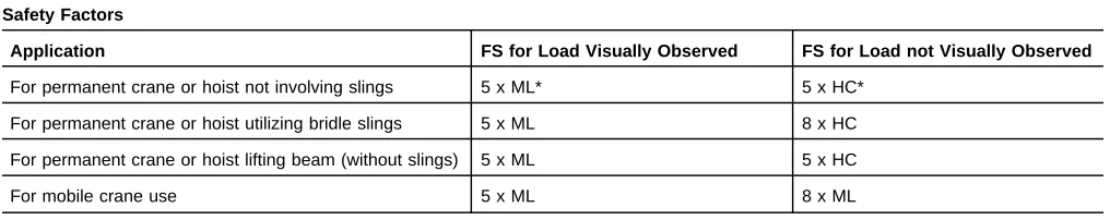
(3) Slings. Special purpose slings for intake gantry and draft tube gantry crane use should be made of corro-sion resistant rope and galvanized fittings. Ultimate strength of sling assemblies should provide a safety factor (FS) as shown in Table 6-1 based on the maximum load. The slings should normally also have a FS of 2 based on the hoist pullout torque, maximum controlled torque, or crane-tipping load. Exceptions should be clearly noted and justified in the mechanical design memorandum. A lesser FS may be used provided that by detailed analysis, it can be shown that under imbalanced load conditions a FS of 5 is provided for the sling leg or lifting beam com-ponents having increased loads. Sling clevis pins and other pins requiring disassembly under normal use should have ample clearance to minimize binding under average field-handling conditions. A 1.6-3.2-mm (1/16-1/8-in.) clearance is preferred for average field-handling con-venience. Design of intermediate links, storage links, support beams, and sling storage provisions should con-sider convenience and safe handling along with required strength.
6-4.
6-4. HoistsHoists
a. General. Fixed hoist applications in powerhouses include operation of intake gates requiring emergency closure capability, operation of gates and weirs requiring automatic or remote control, and miscellaneous lifts non-accessible to a crane. Fixed hoists may be of several
types, the most common being hydraulic and drum-wire rope. Portable equipment is preferable to fixed hoists from a maintenance standpoint and should be considered for all applications with infrequent, noncritical usage.
b. Intake gate hoists.
(1) General.
(a) Fixed gate hoists. These hoists are applicable for vertical lift, wheeled, or roller-mounted gates. The main purpose of fixed hoists is to provide emergency closure. The normal use of fixed hoists will be for maintenance and repair operations. Potential conditions which could require emergency closure include loss of wicket gate control, head cover failure, an inadvertently opened or failed access hatch, or precautionary closures during abnormal operation. The frequency of such emergencies is recognized as remote. However, the potential for major damage does exist, and the emergency closure provisions of fixed hoists are justified. The design should provide maximum dependability and rapid closure under remote control plus backup manual closure under power failure. In addition, necessary provisions for normal gate opera-tions should be included. The type of hoist selected will depend upon the size of gates involved and the configura-tion of the intake structure. The three types of fixed hoists generally considered are direct acting hydraulic hoists, hoists consisting of hydraulic cylinders connected by wire rope through deflector sheaves to the gates, and drum-wire rope hoists.
[image:27.612.53.561.563.664.2](b) Performance criteria. Closure of all gates on a single unit should be accomplished simultaneously and within 10 min from initiation of the closure sequence. The lowering speed of the gate at the point-of-contact with the sill should not exceed 0.05 m/s (10 fpm). Gate-raising speeds are not critical. Depending on size, it is
Table 6-1 Safety Factors
Application FS for Load Visually Observed FS for Load not Visually Observed
For permanent crane or hoist not involving slings 5 x ML* 5 x HC*
For permanent crane or hoist utilizing bridle slings 5 x ML 8 x HC
For permanent crane or hoist lifting beam (without slings) 5 x ML 5 x HC
For mobile crane use 5 x ML 8 x ML
* ML = Maximum load to be picked up; HC = Hoist capacity rated.