DEPT OF CSE & IT VSSUT, Burla
LECTURE NOTES
ON
SOFTWARE ENGINEERING
Course Code: BCS-306
By
Dr. H.S.Behera Asst. Prof K.K.Sahu Asst. Prof Gargi BhattacharjeeDISCLAIMER
THIS DOCUMENT DOES NOT CLAIM ANY ORIGINALITY AND
CANNOT BE USED AS A SUBSTITUTE FOR PRESCRIBED
TEXTBOOKS. THE INFORMATION PRESENTED HERE IS
MERELY A COLLECTION BY THE COMMITTEE MEMBERS FOR
THEIR RESPECTIVE TEACHING ASSIGNMENTS. VARIOUS
TEXT BOOKS AS WELL AS FREELY AVAILABLE MATERIAL
FROM INTERNET WERE CONSULTED FOR PREPARING THIS
DOCUMENT. THE OWNERSHIP OF THE INFORMATION LIES
WITH THE RESPECTIVE AUTHORS OR INSTITUTIONS.
DEPT OF CSE & IT VSSUT, Burla
SYLLABUS
Module I:Introductory concepts: Introduction, definition, objectives, Life cycle – Requirements analysis and specification. Design and Analysis: Cohesion and coupling, Data flow oriented Design: Transform centered design, Transaction centered design. Analysis of specific systems like Inventory control, Reservation system.
Module II:
Object-oriented Design: Object modeling using UML, use case diagram, class diagram, interaction diagrams: activity diagram, unified development process.
Module III:
Implementing and Testing: Programming language characteristics, fundamentals, languages, classes, coding style efficiency. Testing: Objectives, black box and white box testing, various testing strategies, Art of debugging. Maintenance, Reliability and Availability: Maintenance: Characteristics, controlling factors, maintenance tasks, side effects, preventive maintenance – Re Engineering – Reverse Engineering – configuration management – Maintenance tools and techniques. Reliability: Concepts, Errors, Faults, Repair and availability, reliability and availability models. Recent trends and developments.
Module IV:
Software quality: SEI CMM and ISO-9001. Software reliability and fault-tolerance, software project planning, monitoring, and control. Computer-aided software engineering (CASE), Component model of software development, Software reuse.
Text Book:
1. Mall Rajib, Fundamentals of Software Engineering, PHI.
CONTENTS
Module 1:Lecture 1: Introduction to Software Engineering
Lecture 2: Software Development Life Cycle- Classical Waterfall Model Lecture 3: Iterative Waterfall Model, Prototyping Model, Evolutionary Model Lecture 4: Spiral Model
Lecture 5: Requirements Analysis and Specification
Lecture 6: Problems without a SRS document, Decision Tree, Decision Table Lecture 7: Formal System Specification
Lecture 8: Software Design Lecture 9: Software Design Strategies
Lecture 10: Software Analysis & Design Tools Lecture 11: Structured Design
Module 2:
Lecture 12: Object Modelling Using UML Lecture 13: Use Case Diagram
Lecture 14: Class Diagrams Lecture 15: Interaction Diagrams
DEPT OF CSE & IT VSSUT, Burla Module 3:
Lecture 17: Coding Lecture 18: Testing
Lecture 19: Black-Box Testing Lecture 20: White-Box Testing
Lecture 21: White-Box Testing (cont..)
Lecture 22: Debugging, Integration and System Testing Lecture 23: Integration Testing
Lecture 24: Software Maintenance
Lecture 25: Software Maintenance Process Models
Lecture 26: Software Reliability and Quality Management Lecture 27: Reliability Growth Models
Module 4:
Lecture 28: Software Quality
Lecture 29: SEI Capability Maturity Model Lecture 30: Software Project Planning
Lecture 31: Metrics for Software Project Size Estimation
Lecture 32: Heuristic Techniques, Analytical Estimation Techniques
Lecture 33: COCOMO Model
Lecture 34: Intermediate COCOMO Model
Lecture 35: Staffing Level Estimation
Lecture 36: Project Scheduling
Lecture 37: Organization Structure Lecture 38: Risk Management
Lecture 39: Computer Aided Software Engineering
Lecture 40: Software Reuse
Lecture 41: Reuse Approach
DEPT OF CSE & IT VSSUT, Burla
MODULE 1
LECTURE NOTE 1
INTRODUCTION TO SOFTWARE ENGINEERING
The term software engineering is composed of two words, software and engineering.
Software is more than just a program code. A program is an executable code, which serves some computational purpose. Software is considered to be a collection of executable programming code, associated libraries and documentations. Software, when made for a specific requirement is called software product.
Engineering on the other hand, is all about developing products, using well-defined, scientific principles and methods.
So, we can define software engineering as an engineering branch associated with the development of software product using well-defined scientific principles, methods and procedures. The outcome of software engineering is an efficient and reliable software product.
IEEE defines software engineering as:
The application of a systematic, disciplined, quantifiable approach to the development, operation and maintenance of software.
We can alternatively view it as a systematic collection of past experience. The experience is arranged in the form of methodologies and guidelines. A small program can be written without using software engineering principles. But if one wants to develop a large software product, then software engineering principles are absolutely necessary to achieve a good quality software cost effectively.
Without using software engineering principles it would be difficult to develop large programs. In industry it is usually needed to develop large programs to accommodate multiple functions. A problem with developing such large commercial programs is that the complexity and difficulty levels of the programs increase exponentially with their sizes. Software engineering helps to reduce this programming complexity. Software engineering principles use two important techniques to reduce problem complexity: abstraction and decomposition. The principle of abstraction implies that a problem can be simplified by omitting irrelevant details. In other words, the main purpose of abstraction is to consider only those aspects of the problem that are relevant for certain purpose and suppress other aspects that are not relevant for the given purpose. Once the simpler problem is solved, then the omitted details can be taken into consideration to solve the next lower level abstraction, and so on. Abstraction is a powerful way of reducing the complexity of the problem. The other approach to tackle problem complexity is
decomposition. In this technique, a complex problem is divided into several smaller problems and then the smaller problems are solved one by one. However, in this technique any random decomposition of a problem into smaller parts will not help. The problem has to be decomposed such that each component of the decomposed problem can be solved independently and then the solution of the different components can be combined to get the full solution. A good decomposition of a problem should minimize interactions among various components. If the different subcomponents are interrelated, then the different components cannot be solved separately and the desired reduction in complexity will not be realized.
NEED OF SOFTWARE ENGINEERING
The need of software engineering arises because of higher rate of change in user requirements and environment on which the software is working.
Large software - It is easier to build a wall than to a house or building, likewise, as the size of software become large engineering has to step to give it a scientific process.
Scalability- If the software process were not based on scientific and engineering concepts, it would be easier to re-create new software than to scale an existing one.
Cost- As hardware industry has shown its skills and huge manufacturing has lower down the price of computer and electronic hardware. But the cost of software remains high if proper process is not adapted.
Dynamic Nature- The always growing and adapting nature of software hugely depends
upon the environment in which the user works. If the nature of software is always changing, new enhancements need to be done in the existing one. This is where software engineering plays a good role.
Quality Management- Better process of software development provides better and quality software product.
CHARACTERESTICS OF GOOD SOFTWARE
A software product can be judged by what it offers and how well it can be used. This software must satisfy on the following grounds:
Operational
Transitional
DEPT OF CSE & IT VSSUT, Burla
Well-engineered and crafted software is expected to have the following characteristics:
Operational
This tells us how well software works in operations. It can be measured on:
Budget Usability Efficiency Correctness Functionality Dependability Security Safety Transitional
This aspect is important when the software is moved from one platform to another:
Portability
Interoperability
Reusability
Adaptability
Maintenance
This aspect briefs about how well a software has the capabilities to maintain itself in the ever-changing environment:
Modularity
Maintainability
Flexibility
Scalability
In short, Software engineering is a branch of computer science, which uses well-defined engineering concepts required to produce efficient, durable, scalable, in-budget and on-time software products
LECTURE NOTE 2
SOFTWARE DEVELOPMENT LIFE CYCLE
LIFE CYCLE MODELA software life cycle model (also called process model) is a descriptive and diagrammatic representation of the software life cycle. A life cycle model represents all the activities required to make a software product transit through its life cycle phases. It also captures the order in which these activities are to be undertaken. In other words, a life cycle model maps the different activities performed on a software product from its inception to retirement. Different life cycle models may map the basic development activities to phases in different ways. Thus, no matter which life cycle model is followed, the basic activities are included in all life cycle models though the activities may be carried out in different orders in different life cycle models. During any life cycle phase, more than one activity may also be carried out.
THE NEED FOR A SOFTWARE LIFE CYCLE MODEL
The development team must identify a suitable life cycle model for the particular project and then adhere to it. Without using of a particular life cycle model the development of a software product would not be in a systematic and disciplined manner. When a software product is being developed by a team there must be a clear understanding among team members about when and what to do. Otherwise it would lead to chaos and project failure. This problem can be illustrated by using an example. Suppose a software development problem is divided into several parts and the parts are assigned to the team members. From then on, suppose the team members are allowed the freedom to develop the parts assigned to them in whatever way they like. It is possible that one member might start writing the code for his part, another might decide to prepare the test documents first, and some other engineer might begin with the design phase of the parts assigned to him. This would be one of the perfect recipes for project failure. A software life cycle model defines entry and exit criteria for every phase. A phase can start only if its phase-entry criteria have been satisfied. So without software life cycle model the entry and exit criteria for a phase cannot be recognized. Without software life cycle models it becomes difficult for software project managers to monitor the progress of the project.
Different software life cycle models
Many life cycle models have been proposed so far. Each of them has some advantages as well as some disadvantages. A few important and commonly used life cycle models are as follows:
DEPT OF CSE & IT VSSUT, Burla
Iterative Waterfall Model Prototyping Model Evolutionary Model Spiral Model
1. CLASSICAL WATERFALL MODEL
The classical waterfall model is intuitively the most obvious way to develop software. Though the classical waterfall model is elegant and intuitively obvious, it is not a practical model in the sense that it cannot be used in actual software development projects. Thus, this model can be considered to be a theoretical way of developing software. But all other life cycle models are essentially derived from the classical waterfall model. So, in order to be able to appreciate other life cycle models it is necessary to learn the classical waterfall model. Classical waterfall model divides the life cycle into the following phases as shown in fig.2.1:
Fig 2.1: Classical Waterfall Model
Feasibility study - The main aim of feasibility study is to determine whether it would be financially and technically feasible to develop the product.
At first project managers or team leaders try to have a rough understanding of what is required to be done by visiting the client side. They study different input data to the system and output data to be produced by the system. They study what kind of processing is needed to be done on these data and they look at the various constraints on the behavior of the system.
After they have an overall understanding of the problem they investigate the different solutions that are possible. Then they examine each of the solutions in terms of what kind of resources required, what would be the cost of development and what would be the development time for each solution.
Based on this analysis they pick the best solution and determine whether the solution is feasible financially and technically. They check whether the customer budget would meet the cost of the product and whether they have sufficient technical expertise in the area of development.
Requirements analysis and specification: - The aim of the requirements analysis and specification phase is to understand the exact requirements of the customer and to document them properly. This phase consists of two distinct activities, namely
Requirements gathering and analysis Requirements specification
The goal of the requirements gathering activity is to collect all relevant information from the customer regarding the product to be developed. This is done to clearly understand the customer requirements so that incompleteness and inconsistencies are removed.
The requirements analysis activity is begun by collecting all relevant data regarding the product to be developed from the users of the product and from the customer through interviews and discussions. For example, to perform the requirements analysis of a business accounting software required by an organization, the analyst might interview all the accountants of the organization to ascertain their requirements. The data collected from such a group of users usually contain several contradictions and ambiguities, since each user typically has only a partial and incomplete view of the system. Therefore it is necessary to identify all ambiguities and contradictions in the requirements and resolve them through further discussions with the customer. After all ambiguities, inconsistencies, and incompleteness have been resolved and all the requirements properly understood, the requirements specification activity can start. During this activity, the user requirements are systematically organized into a Software Requirements Specification (SRS) document. The customer requirements identified during the requirements gathering and analysis activity are organized into a SRS document. The important components of this document are functional requirements, the nonfunctional requirements, and the goals of implementation.
DEPT OF CSE & IT VSSUT, Burla
Design: - The goal of the design phase is to transform the requirements specified in the SRS document into a structure that is suitable for implementation in some programming language. In technical terms, during the design phase the software architecture is derived from the SRS document. Two distinctly different approaches are available: the traditional design approach and the object-oriented design approach.
Traditional design approach -Traditional design consists of two different activities; first a structured analysis of the requirements specification is carried out where the detailed structure of the problem is examined. This is followed by a structured design activity. During structured design, the results of structured analysis are transformed into the software design.
Object-oriented design approach -In this technique, various objects that occur in the problem domain and the solution domain are first identified, and the different relationships that exist among these objects are identified. The object structure is further refined to obtain the detailed design.
Coding and unit testing:-The purpose of the coding phase (sometimes called the
implementation phase) of software development is to translate the software design into source code. Each component of the design is implemented as a program module. The end-product of this phase is a set of program modules that have been individually tested. During this phase, each module is unit tested to determine the correct working of all the individual modules. It involves testing each module in isolation as this is the most efficient way to debug the errors identified at this stage.
Integration and system testing: -Integration of different modules is undertaken once they have been coded and unit tested. During the integration and system testing phase, the modules are integrated in a planned manner. The different modules making up a software product are almost never integrated in one shot. Integration is normally carried out incrementally over a number of steps. During each integration step, the partially integrated system is tested and a set of previously planned modules are added to it. Finally, when all the modules have been successfully integrated and tested, system testing is carried out. The goal of system testing is to ensure that the developed system conforms to its requirements laid out in the SRS document. System testing usually consists of three different kinds of testing activities:
α – testing: It is the system testing performed by the development team. β –testing: It is the system testing performed by a friendly set of customers.
Acceptance testing: It is the system testing performed by the customer himself after the product delivery to determine whether to accept or reject the delivered product.
System testing is normally carried out in a planned manner according to the system test plan document. The system test plan identifies all testing-related activities that must be performed,
specifies the schedule of testing, and allocates resources. It also lists all the test cases and the expected outputs for each test case.
Maintenance: -Maintenance of a typical software product requires much more than the effort necessary to develop the product itself. Many studies carried out in the past confirm this and indicate that the relative effort of development of a typical software product to its maintenance effort is roughly in the 40:60 ratios. Maintenance involves performing any one or more of the following three kinds of activities:
Correcting errors that were not discovered during the product development phase. This is called corrective maintenance.
Improving the implementation of the system, and enhancing the functionalities of the system according to the customer’s requirements. This is called perfective maintenance. Porting the software to work in a new environment. For example, porting may be
required to get the software to work on a new computer platform or with a new operating system. This is called adaptive maintenance.
Shortcomings of the classical waterfall model
The classical waterfall model is an idealistic one since it assumes that no development error is ever committed by the engineers during any of the life cycle phases. However, in practical development environments, the engineers do commit a large number of errors in almost every phase of the life cycle. The source of the defects can be many: oversight, wrong assumptions, use of inappropriate technology, communication gap among the project engineers, etc. These defects usually get detected much later in the life cycle. For example, a design defect might go unnoticed till we reach the coding or testing phase. Once a defect is detected, the engineers need to go back to the phase where the defect had occurred and redo some of the work done during that phase and the subsequent phases to correct the defect and its effect on the later phases. Therefore, in any practical software development work, it is not possible to strictly follow the classical waterfall model.
DEPT OF CSE & IT VSSUT, Burla
LECTURE NOTE 3
2. ITERATIVE WATERFALL MODEL
To overcome the major shortcomings of the classical waterfall model, we come up with the iterative waterfall model.
Fig 3.1 : Iterative Waterfall Model
Here, we provide feedback paths for error correction as & when detected later in a phase. Though errors are inevitable, but it is desirable to detect them in the same phase in which they occur. If so, this can reduce the effort to correct the bug.
The advantage of this model is that there is a working model of the system at a very early stage of development which makes it easier to find functional or design flaws. Finding issues at an early stage of development enables to take corrective measures in a limited budget. The disadvantage with this SDLC model is that it is applicable only to large and bulky software development projects. This is because it is hard to break a small software system into further small serviceable increments/modules.
3. PRTOTYPING MODEL Prototype
A prototype is a toy implementation of the system. A prototype usually exhibits limited functional capabilities, low reliability, and inefficient performance compared to the actual software. A prototype is usually built using several shortcuts. The shortcuts might involve using inefficient, inaccurate, or dummy functions. The shortcut implementation of a function, for example, may produce the desired results by using a table look-up instead of performing the actual computations. A prototype usually turns out to be a very crude version of the actual system.
Need for a prototype in software development
There are several uses of a prototype. An important purpose is to illustrate the input data formats, messages, reports, and the interactive dialogues to the customer. This is a valuable mechanism for gaining better understanding of the customer’s needs:
how the screens might look like how the user interface would behave how the system would produce outputs
Another reason for developing a prototype is that it is impossible to get the perfect product in the first attempt. Many researchers and engineers advocate that if you want to develop a good product you must plan to throw away the first version. The experience gained in developing the prototype can be used to develop the final product.
A prototyping model can be used when technical solutions are unclear to the development team. A developed prototype can help engineers to critically examine the technical issues associated with the product development. Often, major design decisions depend on issues like the response time of a hardware controller, or the efficiency of a sorting algorithm, etc. In such circumstances, a prototype may be the best or the only way to resolve the technical issues.
A prototype of the actual product is preferred in situations such as: • User requirements are not complete
DEPT OF CSE & IT VSSUT, Burla
Fig 3.2: Prototype Model
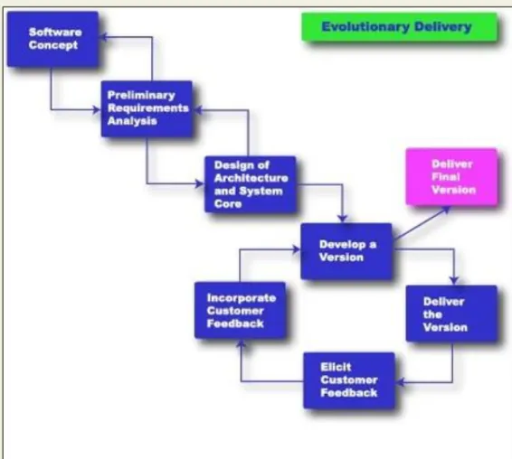
4. EVOLUTIONARY MODEL
It is also called successive versions model or incremental model. At first, a simple working model is built. Subsequently it undergoes functional improvements & we keep on adding new functions till the desired system is built.
Applications:
Large projects where you can easily find modules for incremental implementation. Often used when the customer wants to start using the core features rather than waiting for the full software.
Also used in object oriented software development because the system can be easily portioned into units in terms of objects.
Advantages:
User gets a chance to experiment partially developed system Reduce the error because the core modules get tested thoroughly. Disadvantages:
It is difficult to divide the problem into several versions that would be acceptable to the customer which can be incrementally implemented & delivered.
DEPT OF CSE & IT VSSUT, Burla
LECTURE NOTE 4
5. SPIRAL MODEL
The Spiral model of software development is shown in fig. 4.1. The diagrammatic representation of this model appears like a spiral with many loops. The exact number of loops in the spiral is not fixed. Each loop of the spiral represents a phase of the software process. For example, the innermost loop might be concerned with feasibility study, the next loop with requirements specification, the next one with design, and so on. Each phase in this model is split into four sectors (or quadrants) as shown in fig. 4.1. The following activities are carried out during each phase of a spiral model.
Fig 4.1: Spiral Model
First quadrant (Objective Setting)
• During the first quadrant, it is needed to identify the objectives of the phase. • Examine the risks associated with these objectives.
Second Quadrant (Risk Assessment and Reduction)
• A detailed analysis is carried out for each identified project risk.
• Steps are taken to reduce the risks. For example, if there is a risk that the requirements are inappropriate, a prototype system may be developed.
Third Quadrant (Development and Validation)
• Develop and validate the next level of the product after resolving the identified risks.
Fourth Quadrant (Review and Planning)
• Review the results achieved so far with the customer and plan the next iteration around the spiral.
• Progressively more complete version of the software gets built with each iteration around the spiral.
Circumstances to use spiral model
The spiral model is called a meta model since it encompasses all other life cycle models. Risk handling is inherently built into this model. The spiral model is suitable for development of technically challenging software products that are prone to several kinds of risks. However, this model is much more complex than the other models – this is probably a factor deterring its use in ordinary projects.
Comparison of different life-cycle models
The classical waterfall model can be considered as the basic model and all other life cycle models as embellishments of this model. However, the classical waterfall model cannot be used in practical development projects, since this model supports no mechanism to handle the errors committed during any of the phases.
This problem is overcome in the iterative waterfall model. The iterative waterfall model is probably the most widely used software development model evolved so far. This model is simple to understand and use. However this model is suitable only for well-understood problems; it is not suitable for very large projects and for projects that are subject to many risks.
The prototyping model is suitable for projects for which either the user requirements or the underlying technical aspects are not well understood. This model is especially popular for development of the user-interface part of the projects.
DEPT OF CSE & IT VSSUT, Burla
The evolutionary approach is suitable for large problems which can be decomposed into a set of modules for incremental development and delivery. This model is also widely used for object-oriented development projects. Of course, this model can only be used if the incremental delivery of the system is acceptable to the customer.
The spiral model is called a meta model since it encompasses all other life cycle models. Risk handling is inherently built into this model. The spiral model is suitable for development of technically challenging software products that are prone to several kinds of risks. However, this model is much more complex than the other models – this is probably a factor deterring its use in ordinary projects.
The different software life cycle models can be compared from the viewpoint of the customer. Initially, customer confidence in the development team is usually high irrespective of the development model followed. During the lengthy development process, customer confidence normally drops off, as no working product is immediately visible. Developers answer customer queries using technical slang, and delays are announced. This gives rise to customer resentment. On the other hand, an evolutionary approach lets the customer experiment with a working product much earlier than the monolithic approaches. Another important advantage of the incremental model is that it reduces the customer’s trauma of getting used to an entirely new system. The gradual introduction of the product via incremental phases provides time to the customer to adjust to the new product. Also, from the customer’s financial viewpoint, incremental development does not require a large upfront capital outlay. The customer can order the incremental versions as and when he can afford them.
LECTURE NOTE 5
REQUIREMENTS ANALYSIS AND SPECIFICATION
Before we start to develop our software, it becomes quite essential for us to understand and document the exact requirement of the customer. Experienced members of the development team carry out this job. They are called as system analysts.
The analyst starts requirements gathering and analysis activity by collecting all information from the customer which could be used to develop the requirements of the system. He then analyzes the collected information to obtain a clear and thorough understanding of the product to be developed, with a view to remove all ambiguities and inconsistencies from the initial customer perception of the problem. The following basic questions pertaining to the project should be clearly understood by the analyst in order to obtain a good grasp of the problem:
• What is the problem?
• Why is it important to solve the problem? • What are the possible solutions to the problem?
• What exactly are the data input to the system and what exactly are the data output by the system?
• What are the likely complexities that might arise while solving the problem?
• If there are external software or hardware with which the developed software has to interface, then what exactly would the data interchange formats with the external system be?
After the analyst has understood the exact customer requirements, he proceeds to identify and resolve the various requirements problems. The most important requirements problems that the analyst has to identify and eliminate are the problems of anomalies, inconsistencies, and incompleteness. When the analyst detects any inconsistencies, anomalies or incompleteness in the gathered requirements, he resolves them by carrying out further discussions with the end-users and the customers.
Parts of a SRS document
• The important parts of SRS document are: Functional requirements of the system
Non-functional requirements of the system, and Goals of implementation
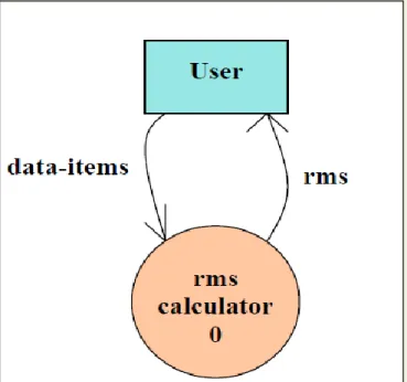
DEPT OF CSE & IT VSSUT, Burla Functional requirements:-
The functional requirements part discusses the functionalities required from the system. The system is considered to perform a set of high-level functions {f
i}. The functional view of the system is shown in fig. 5.1. Each function f
i of the system can be considered as a transformation
of a set of input data (ii) to the corresponding set of output data (o
i). The user can get some meaningful piece of work done using a high-level function.
Fig. 5.1:View of a system performing a set of functions
Nonfunctional requirements:-
Nonfunctional requirements deal with the characteristics of the system which cannot be expressed as functions - such as the maintainability of the system, portability of the system, usability of the system, etc.
Goals of implementation:-
The goals of implementation part documents some general suggestions regarding development. These suggestions guide trade-off among design goals. The goals of implementation section might document issues such as revisions to the system functionalities that may be required in the future, new devices to be supported in the future, reusability issues, etc. These are the items which the developers might keep in their mind during development so that the developed system may meet some aspects that are not required immediately.
Identifying functional requirements from a problem description
The high-level functional requirements often need to be identified either from an informal problem description document or from a conceptual understanding of the problem. Each high-level requirement characterizes a way of system usage by some user to perform some meaningful piece of work. There can be many types of users of a system and their requirements from the system may be very different. So, it is often useful to identify the different types of users who might use the system and then try to identify the requirements from each user’s perspective.
Example: - Consider the case of the library system, where –
F1: Search Book function
Input: an author’s name
Output: details of the author’s books and the location of these books in the library
So the function Search Book (F1) takes the author's name and transforms it into book details. Functional requirements actually describe a set of high-level requirements, where each high-level requirement takes some data from the user and provides some data to the user as an output. Also each high-level requirement might consist of several other functions.
Documenting functional requirements
For documenting the functional requirements, we need to specify the set of functionalities supported by the system. A function can be specified by identifying the state at which the data is to be input to the system, its input data domain, the output data domain, and the type of processing to be carried on the input data to obtain the output data. Let us first try to document the withdraw-cash function of an ATM (Automated Teller Machine) system. The withdraw-cash is a high-level requirement. It has several sub-requirements corresponding to the different user interactions. These different interaction sequences capture the different scenarios.
Example: - Withdraw Cash from ATM
R1: withdraw cash
Description: The withdraw cash function first determines the type of account that the user has and the account number from which the user wishes to withdraw cash. It checks the balance to determine whether the requested amount is available in the account. If enough balance is available, it outputs the required cash; otherwise it generates an error message.
DEPT OF CSE & IT VSSUT, Burla
R1.1 select withdraw amount option Input: “withdraw amount” option
Output: user prompted to enter the account type R1.2: select account type
Input: user option
Output: prompt to enter amount R1.3: get required amount
Input: amount to be withdrawn in integer values greater than 100 and less than 10,000 in multiples of 100.
Output: The requested cash and printed transaction statement.
Processing: the amount is debited from the user’s account if sufficient balance is available, otherwise an error message displayed
Properties of a good SRS document
The important properties of a good SRS document are the following:
Concise. The SRS document should be concise and at the same time unambiguous, consistent, and complete. Verbose and irrelevant descriptions reduce readability and also increase error possibilities.
Structured. It should be well-structured. A well-structured document is easy to understand and modify. In practice, the SRS document undergoes several revisions to cope up with the customer requirements. Often, the customer requirements evolve over a period of time. Therefore, in order to make the modifications to the SRS document easy, it is important to make the document well-structured.
Black-box view. It should only specify what the system should do and refrain from stating how to do these. This means that the SRS document should specify the external behavior of the system and not discuss the implementation issues. The SRS document should view the system to be developed as black box, and should specify the externally visible behavior of the system. For this reason, the SRS document is also called the black-box specification of a system.
Conceptual integrity. It should show conceptual integrity so that the reader can easily understand it.
Response to undesired events. It should characterize acceptable responses to undesired events. These are called system response to exceptional conditions.
Verifiable. All requirements of the system as documented in the SRS document should be verifiable. This means that it should be possible to determine whether or not requirements have been met in an implementation.
Problems without a SRS document
The important problems that an organization would face if it does not develop a SRS document are as follows:
Without developing the SRS document, the system would not be implemented according to customer needs.
Software developers would not know whether what they are developing is what exactly required by the customer.
Without SRS document, it will be very much difficult for the maintenance engineers to understand the functionality of the system.
It will be very much difficult for user document writers to write the users’ manuals properly without understanding the SRS document.
Problems with an unstructured specification
• It would be very much difficult to understand that document.
• It would be very much difficult to modify that document. • Conceptual integrity in that document would not be shown. • The SRS document might be unambiguous and inconsistent.
DEPT OF CSE & IT VSSUT, Burla
LECTURE NOTE 6
DECISION TREE
A decision tree gives a graphic view of the processing logic involved in decision making and the corresponding actions taken. The edges of a decision tree represent conditions and the leaf nodes represent the actions to be performed depending on the outcome of testing the condition.
Example: -
Consider Library Membership Automation Software (LMS) where it should support the following three options:
New member
Renewal
Cancel membership
New member option-
Decision: When the 'new member' option is selected, the software asks details about the member like the member's name, address, phone number etc.
Action: If proper information is entered then a membership record for the member is created and a bill is printed for the annual membership charge plus the security deposit payable.
Renewal option-
Decision: If the 'renewal' option is chosen, the LMS asks for the member's name and his membership number to check whether he is a valid member or not.
Action: If the membership is valid then membership expiry date is updated and the annual membership bill is printed, otherwise an error message is displayed.
Cancel membership option-
Decision: If the 'cancel membership' option is selected, then the software asks for member's name and his membership number.
Action: The membership is cancelled, a cheque for the balance amount due to the member is printed and finally the membership record is deleted from the database.
The following tree (fig. 6.1) shows the graphical representation of the above example.
Fig 6.1: Decision Tree of LMS
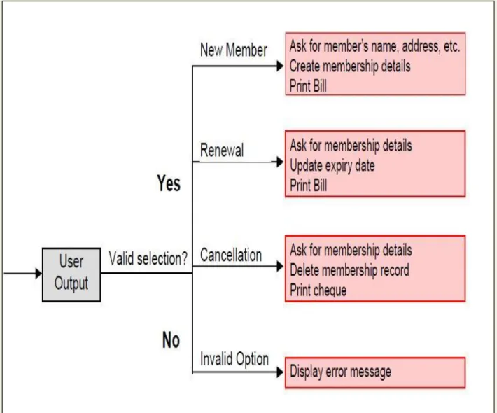
DECISION TABLE
A decision table is used to represent the complex processing logic in a tabular or a matrix form. The upper rows of the table specify the variables or conditions to be evaluated. The lower rows of the table specify the actions to be taken when the corresponding conditions are satisfied. A column in a table is called a rule. A rule implies that if a condition is true, then the corresponding action is to be executed.
Example: -
Consider the previously discussed LMS example. The following decision table (fig. 6.2) shows how to represent the LMS problem in a tabular form. Here the table is divided into two parts, the upper part shows the conditions and the lower part shows what actions are taken. Each column of the table is a rule.
DEPT OF CSE & IT VSSUT, Burla
Fig. 6.2:Decision table for LMS
From the above table you can easily understand that, if the valid selection condition is false then the action taken for this condition is 'display error message'. Similarly, the actions taken for other conditions can be inferred from the table.
LECTURE NOTE 7
FORMAL SYSTEM SPECIFICATION
Formal TechniqueA formal technique is a mathematical method to specify a hardware and/or software system, verify whether a specification is realizable, verify that an implementation satisfies its specification, prove properties of a system without necessarily running the system, etc. The mathematical basis of a formal method is provided by the specification language.
Formal Specification Language
A formal specification language consists of two sets syn and sem, and a relation sat between them. The set syn is called the syntactic domain, the set sem is called the semantic domain, and the relation sat is called the satisfaction relation. For a given specification syn, and model of the system sem, if sat (syn, sem), then syn is said to be the specification of sem, and sem is said to be the specificand of syn.
Syntactic Domains
The syntactic domain of a formal specification language consists of an alphabet of symbols and set of formation rules to construct well-formed formulas from the alphabet. The well-formed formulas are used to specify a system.
Semantic Domains
Formal techniques can have considerably different semantic domains. Abstract data type specification languages are used to specify algebras, theories, and programs. Programming languages are used to specify functions from input to output values. Concurrent and distributed system specification languages are used to specify state sequences, event sequences, state-transition sequences, synchronization trees, partial orders, state machines, etc.
Satisfaction Relation
Given the model of a system, it is important to determine whether an element of the semantic domain satisfies the specifications. This satisfaction is determined by using a homomorphism known as semantic abstraction function. The semantic abstraction function maps the elements of the semantic domain into equivalent classes. There can be different specifications describing different aspects of a system model, possibly using different specification languages. Some of these specifications describe the system’s behavior and the others describe the system’s structure. Consequently, two broad classes of semantic abstraction functions are defined: those that preserve a system’s behavior and those that preserve a system’s structure.
DEPT OF CSE & IT VSSUT, Burla Model-oriented vs. property-oriented approaches
Formal methods are usually classified into two broad categories – model – oriented and property – oriented approaches. In a model-oriented style, one defines a system’s behavior directly by constructing a model of the system in terms of mathematical structures such as tuples, relations, functions, sets, sequences, etc.
In the property-oriented style, the system's behavior is defined indirectly by stating its properties, usually in the form of a set of axioms that the system must satisfy.
Example:-
Let us consider a simple producer/consumer example. In a property-oriented style, it is probably started by listing the properties of the system like: the consumer can start consuming only after the producer has produced an item; the producer starts to produce an item only after the consumer has consumed the last item, etc. A good example of a producer-consumer problem is CPU-Printer coordination. After processing of data, CPU outputs characters to the buffer for printing. Printer, on the other hand, reads characters from the buffer and prints them. The CPU is constrained by the capacity of the buffer, whereas the printer is constrained by an empty buffer. Examples of property-oriented specification styles are axiomatic specification and algebraic specification.
In a model-oriented approach, we start by defining the basic operations, p (produce) and c (consume). Then we can state that S1 + p → S, S + c → S1. Thus the model-oriented approaches essentially specify a program by writing another, presumably simpler program. Examples of popular model-oriented specification techniques are Z, CSP, CCS, etc.
Model-oriented approaches are more suited to use in later phases of life cycle because here even minor changes to a specification may lead to drastic changes to the entire specification. They do not support logical conjunctions (AND) and disjunctions (OR).
Property-oriented approaches are suitable for requirements specification because they can be easily changed. They specify a system as a conjunction of axioms and you can easily replace one axiom with another one.
Operational Semantics
Informally, the operational semantics of a formal method is the way computations are represented. There are different types of operational semantics according to what is meant by a single run of the system and how the runs are grouped together to describe the behavior of the system. Some commonly used operational semantics are as follows:
Linear Semantics:-
In this approach, a run of a system is described by a sequence (possibly infinite) of events or states. The concurrent activities of the system are represented by non-deterministic interleavings of the automatic actions. For example, a concurrent activity a║b is represented by the set of
sequential activities a;b and b;a. This is simple but rather unnatural representation of concurrency. The behavior of a system in this model consists of the set of all its runs. To make this model realistic, usually justice and fairness restrictions are imposed on computations to exclude the unwanted interleavings.
Branching Semantics:-
In this approach, the behavior of a system is represented by a directed graph. The nodes of the graph represent the possible states in the evolution of a system. The descendants of each node of the graph represent the states which can be generated by any of the atomic actions enabled at that state. Although this semantic model distinguishes the branching points in a computation, still it represents concurrency by interleaving.
Maximally parallel semantics:-
In this approach, all the concurrent actions enabled at any state are assumed to be taken together. This is again not a natural model of concurrency since it implicitly assumes the availability of all the required computational resources.
Partial order semantics:-
Under this view, the semantics ascribed to a system is a structure of states satisfying a partial order relation among the states (events). The partial order represents a precedence ordering among events, and constraints some events to occur only after some other events have occurred; while the occurrence of other events (called concurrent events) is considered to be incomparable. This fact identifies concurrency as a phenomenon not translatable to any interleaved representation.
Formal methods possess several positive features, some of which are discussed below.
Formal specifications encourage rigor. Often, the very process of construction of a rigorous specification is more important than the formal specification itself. The construction of a rigorous specification clarifies several aspects of system behavior that are not obvious in an informal specification.
Formal methods usually have a well-founded mathematical basis. Thus, formal specifications are not only more precise, but also mathematically sound and can be used to reason about the properties of a specification and to rigorously prove that an implementation satisfies its specifications.
Formal methods have well-defined semantics. Therefore, ambiguity in specifications is automatically avoided when one formally specifies a system.
DEPT OF CSE & IT VSSUT, Burla
The mathematical basis of the formal methods facilitates automating the analysis of specifications. For example, a tableau-based technique has been used to automatically check the consistency of specifications. Also, automatic theorem proving techniques can be used to verify that an implementation satisfies its specifications. The possibility of automatic verification is one of the most important advantages of formal methods.
Formal specifications can be executed to obtain immediate feedback on the features of the specified system. This concept of executable specifications is related to rapid prototyping. Informally, a prototype is a “toy” working model of a system that can provide immediate feedback on the behavior of the specified system, and is especially useful in checking the completeness of specifications.
Limitations of formal requirements specification
It is clear that formal methods provide mathematically sound frameworks within large, complex systems can be specified, developed and verified in a systematic rather than in an ad hoc manner. However, formal methods suffer from several shortcomings, some of which are the following:
Formal methods are difficult to learn and use.
The basic incompleteness results of first-order logic suggest that it is impossible to check absolute correctness of systems using theorem proving techniques.
Formal techniques are not able to handle complex problems. This shortcoming results from the fact that, even moderately complicated problems blow up the complexity of formal specification and their analysis. Also, a large unstructured set of mathematical formulas is difficult to comprehend.
Axiomatic Specification
In axiomatic specification of a system, first-order logic is used to write the pre and post-conditions to specify the operations of the system in the form of axioms. The pre-post-conditions basically capture the conditions that must be satisfied before an operation can successfully be invoked. In essence, the pre-conditions capture the requirements on the input parameters of a function. The post-conditions are the conditions that must be satisfied when a function completes execution for the function to be considered to have executed successfully. Thus, the post-conditions are essentially constraints on the results produced for the function execution to be considered successful.
The following are the sequence of steps that can be followed to systematically develop the axiomatic specifications of a function:
Establish the range of input values over which the function should behave correctly. Also find out other constraints on the input parameters and write it in the form of a predicate.
Specify a predicate defining the conditions which must hold on the output of the function if it behaved properly.
Establish the changes made to the function’s input parameters after execution of the function. Pure mathematical functions do not change their input and therefore this type of assertion is not necessary for pure functions.
Combine all of the above into pre and post conditions of the function.
Example1: -
Specify the pre- and post-conditions of a function that takes a real number as argument and returns half the input value if the input is less than or equal to 100, or else returns double the value.
f (x : real) : real pre : x ∈ R
post : {(x≤100) ∧ (f(x) = x/2)} ∨ {(x>100) ∧ (f(x) = 2∗x)}
Example2: -
Axiomatically specify a function named search which takes an integer array and an integer key value as its arguments and returns the index in the array where the key value is present.
search(X : IntArray, key : Integer) : Integer pre : ∃ i ∈ [Xfirst….Xlast], X[i] = key
post : {(X′[search(X, key)] = key) ∧ (X = X′)}
Here the convention followed is: If a function changes any of its input parameters and if that parameter is named X, and then it is referred to as X′ after the function completes execution faster.
DEPT OF CSE & IT VSSUT, Burla
LECTURE NOTE 8
SOFTWARE DESIGN
Software design is a process to transform user requirements into some suitable form, which helps the programmer in software coding and implementation.
For assessing user requirements, an SRS (Software Requirement Specification) document is created whereas for coding and implementation, there is a need of more specific and detailed requirements in software terms. The output of this process can directly be used into implementation in programming languages.
Software design is the first step in SDLC (Software Design Life Cycle), which moves the concentration from problem domain to solution domain. It tries to specify how to fulfill the requirements mentioned in SRS.
Software Design Levels
Software design yields three levels of results:
Architectural Design - The architectural design is the highest abstract version of the system. It identifies the software as a system with many components interacting with each other. At this level, the designers get the idea of proposed solution domain.
High-level Design- The high-level design breaks the ‘single entity-multiple component’ concept of architectural design into less-abstracted view of sub-systems and modules and depicts their interaction with each other. High-level design focuses on how the system along with all of its components can be implemented in forms of modules. It recognizes modular structure of each sub-system and their relation and interaction among each other.
Detailed Design- Detailed design deals with the implementation part of what is seen as a system and its sub-systems in the previous two designs. It is more detailed towards modules and their implementations. It defines logical structure of each module and their interfaces to communicate with other modules.
Modularization
Modularization is a technique to divide a software system into multiple discrete and independent modules, which are expected to be capable of carrying out task(s) independently. These modules may work as basic constructs for the entire software. Designers tend to design modules such that they can be executed and/or compiled separately and independently.
Modular design unintentionally follows the rules of ‘divide and conquer’ problem-solving strategy this is because there are many other benefits attached with the modular design of a software.
Advantage of modularization:
Smaller components are easier to maintain
Program can be divided based on functional aspects
Desired level of abstraction ca n be brought in the program
Components with high cohesion can be re-used again.
Concurrent execution can be made possible
Desired from security aspect
Concurrency
Back in time, all softwares were meant to be executed sequentially. By sequential execution we mean that the coded instruction will be executed one after another implying only one portion of program being activated at any given time. Say, a software has multiple modules, then only one of all the modules can be found active at any time of execution.
In software design, concurrency is implemented by splitting the software into multiple independent units of execution, like modules and executing them in parallel. In other words, concurrency provides capability to the software to execute more than one part of code in parallel to each other.
It is necessary for the programmers and designers to recognize those modules, which can be made parallel execution.
Example
The spell check feature in word processor is a module of software, which runs alongside the word processor itself.
Coupling and Cohesion
When a software program is modularized, its tasks are divided into several modules based on some characteristics. As we know, modules are set of instructions put together in order to achieve some tasks. They are though, considered as single entity but may refer to each other to work together. There are measures by which the quality of a design of modules and their interaction among them can be measured. These measures are called coupling and cohesion.
Cohesion
Cohesion is a measure that defines the degree of intra-dependability within elements of a module. The greater the cohesion, the better is the program design.
DEPT OF CSE & IT VSSUT, Burla
There are seven types of cohesion, namely –
Co-incidental cohesion - It is unplanned and random cohesion, which might be the result of breaking the program into smaller modules for the sake of modularization. Because it is unplanned, it may serve confusion to the programmers and is generally not-accepted.
Logical cohesion - When logically categorized elements are put together into a module, it is called logical cohesion.
Temporal Cohesion - When elements of module are organized such that they are processed at a similar point in time, it is called temporal cohesion.
Procedural cohesion - When elements of module are grouped together, which are executed sequentially in order to perform a task, it is called procedural cohesion.
Communicational cohesion - When elements of module are grouped together, which are
executed sequentially and work on same data (information), it is called communicational cohesion.
Sequential cohesion - When elements of module are grouped because the output of one
element serves as input to another and so on, it is called sequential cohesion.
Functional cohesion - It is considered to be the highest degree of cohesion, and it is highly expected. Elements of module in functional cohesion are grouped because they all contribute to a single well-defined function. It can also be reused.
Coupling
Coupling is a measure that defines the level of inter-dependability among modules of a program. It tells at what level the modules interfere and interact with each other. The lower the coupling, the better the program.
There are five levels of coupling, namely -
Content coupling - When a module can directly access or modify or refer to the content of another module, it is called content level coupling.
Common coupling- When multiple modules have read and write access to some global
data, it is called common or global coupling.
Control coupling- Two modules are called control-coupled if one of them decides the function of the other module or changes its flow of execution.
Stamp coupling- When multiple modules share common data structure and work on different part of it, it is called stamp coupling.
Data coupling- Data coupling is when two modules interact with each other by means of passing data (as parameter). If a module passes data structure as parameter, then the receiving module should use all its components.
Design Verification
The output of software design process is design documentation, pseudo codes, detailed logic diagrams, process diagrams, and detailed description of all functional or non-functional requirements.
The next phase, which is the implementation of software, depends on all outputs mentioned above.
It is then becomes necessary to verify the output before proceeding to the next phase. The early any mistake is detected, the better it is or it might not be detected until testing of the product. If the outputs of design phase are in formal notation form, then their associated tools for verification should be used otherwise a thorough design review can be used for verification and validation.
By structured verification approach, reviewers can detect defects that might be caused by overlooking some conditions. A good design review is important for good software design, accuracy and quality.
DEPT OF CSE & IT VSSUT, Burla
LECTURE NOTE 9
SOFTWARE DESIGN STRATEGIES
Software design is a process to conceptualize the software requirements into software implementation. Software design takes the user requirements as challenges and tries to find optimum solution. While the software is being conceptualized, a plan is chalked out to find the best possible design for implementing the intended solution.
There are multiple variants of software design. Let us study them briefly:
Structured Design
Structured design is a conceptualization of problem into several well-organized elements of solution. It is basically concerned with the solution design. Benefit of structured design is, it gives better understanding of how the problem is being solved. Structured design also makes it simpler for designer to concentrate on the problem more accurately.
Structured design is mostly based on ‘divide and conquer’ strategy where a problem is broken into several small problems and each small problem is individually solved until the whole problem is solved.
The small pieces of problem are solved by means of solution modules. Structured design emphasis that these modules be well organized in order to achieve precise solution.
These modules are arranged in hierarchy. They communicate with each other. A good structured design always follows some rules for communication among multiple modules, namely -
Cohesion - grouping of all functionally related elements.
Coupling - communication between different modules.
Function Oriented Design
In function-oriented design, the system is comprised of many smaller sub-systems known as functions. These functions are capable of performing significant task in the system. The system is considered as top view of all functions.
Function oriented design inherits some properties of structured design where divide and conquer methodology is used.
This design mechanism divides the whole system into smaller functions, which provides means of abstraction by concealing the information and their operation. These functional modules can share information among themselves by means of information passing and using information available globally.
Another characteristic of functions is that when a program calls a function, the function changes the state of the program, which sometimes is not acceptable by other modules. Function oriented design works well where the system state does not matter and program/functions work on input rather than on a state.
Design Process
The whole system is seen as how data flows in the system by means of data flow diagram.
DFD depicts how functions change the data and state of entire system.
The entire system is logically broken down into smaller units known as functions on the basis of their operation in the system.
Each function is then described at large.
Object Oriented Design
Object oriented design works around the entities and their characteristics instead of functions involved in the software system. This design strategy focuses on entities and its characteristics. The whole concept of software solution revolves around the engaged entities.
Let us see the important concepts of Object Oriented Design:
Objects - All entities involved in the solution design are known as objects. For example, person, banks, company and customers are treated as objects. Every entity has some attributes associated to it and has some methods to perform on the attributes.
Classes - A class is a generalized description of an object. An object is an instance of a class. Class defines all the attributes, which an object can have and methods, which defines the functionality of the object.