Journal of Electrical Engineering, Electronics, Control and Computer Science –
JEEECCS, Volume 6, Issue 20, pages 7-14, 2020
Petri Nets Based Coordination Mechanism for
Cooperative Multi-Robot System
Alexandru-Călin Stan
Department of Automatic Control, Computers and Electronics
Petroleum-Gas University of Ploiesti Ploiesti,Romania
Mihaela Oprea
Department of Automatic Control, Computers and Electronics
Petroleum-Gas University of Ploiesti Ploiesti,Romania
Abstract – The coordination of cooperative multi-robot system is an area which has grown significantly in importance in the last few years due to the latest breakthroughs in robotics technology. Many studies have been done in order to achieve a better understanding in this domain. This paper presents and compares the current coordination techniques and presents two study Petri Nets (PNs) coordination mechanism for a large-scale multi-robot system (MRS) represented by a flexible beverage production line and a small scale cooperative mobile MRS represented by a system with three members.
Keywords-multi-robot system; Petri Nets; coordination; collaborative; cooperative behavior
I. INTRODUCTION
In the field of mobile robotics, the importance of multi-robot cooperative systems (MRS) has grown significant in the last years. Major breakthroughs have been done regarding the main topics concerning these systems, for example the coordination mechanism, communication and task planning mechanism between the entities of the system [17].
As cooperative multi-robot systems require the representation of both types of dynamics, continuous and discrete, it is useful to apply some discrete events systems modeling methods such as Petri Nets [9], [5].In this sense, we have designed a multi-robot coordination mechanism based on Petri Nets that is presented in chapter IV in which is analyzed an example of coordination mechanism of a large scale multi-robot system (MRS) represented by a flexible beverage production line and a small scale cooperative mobile MRS represented by a system with three members.
The paper is organized as follows. Section II presents a review on multi-robot system coordination methods. A Petri Nets based coordination mechanism is introduced in section III. Section IV describes a case study of using the coordination mechanism for a cooperative multi-robot system. The main conclusion
and some future work are presented in the last section of the paper.
II.MULTI-ROBOT SYSTEM COORDINATION A multi-robot system is defined as a system consisting of multiple robots which can cooperate and communicate with each other to accomplish certain given tasks. Two types of MRS can be identified, cooperative and competitive, in this paper is analyzed
the cooperative type of a multi-robot system (MRS).
A cooperative MRS is a system where users or agents are engaged in a common activity, usually from different locations.
Cooperation is a form of work involving teamwork using the same resources and the same tasks. In order to achieve teamwork, the entities involved have to coordinate their activities, share the same goals and activities have to be synchronized and coordinated in order to avoid possible conflicts. [3]
Communication can be defined as a simple exchange of information between system entities. Communication is the process by which individuals communicate their needs, aspirations to the other individuals involved in the process. Communication is the property that makes it possible to collaborate within the system. [13]
One of the main issues in the field of multi-robot systems is their coordination, the performance of the system being directly affected by the quality of coordination and control.
Coordination is the process that makes collaboration between individuals possible, highlights it and is based on communication between them. In literature coordination is defined as "an action to drive interdependencies between activities to achieve a goal." [13].
offline coordination, refers to the adoption of a general set of rules before starting the task. For example, a set of motion control rules can be "forward", "backward", "forward-to-right", etc. [3]
Dynamic coordination, known as reactive or online coordination, is used during task execution and is based on the interpretation of information received from other members of the system [3].
Dynamic coordination can also be divided into two categories: explicitly used in groups of robots with increased complexity (intentional communication between robots in order to collaborate) and implicitly use the dynamics of interaction between robots and the environment.
By contrast, static coordination offers very good results when the complexity of the task is high, but the quality of real-time control can be poor due to the fact that non-rule-based situations can be encountered, while dynamic coordination offers very good performance over real-time, but with increasing complexity it becomes difficult to achieve.
In reality, the complexity of the environment is very high and the dynamics of the system is high, which determines the necessity of using hybrid coordination techniques that contain both static and dynamic coordination elements, both explicit and implicit.
Some research work reported in the literature analyses the state of the art in multi-robot systems coordination from different points of view (see e.g. [19] and [6]). For example, in [19] coordination is viewed as being quantitative and qualitative. The quantitative multi-robot systems coordination includes market economy-based methods (e.g. a distributed approach through negotiation - a bidding-auction approach), decision theoretic based methods (in terms of utility and cost), supervised and unsupervised optimization methods, computational intelligence-based methods etc. On the other part, the qualitative multi-robot systems coordination focuses on the logical level and is based on supervisory control of discrete event systems (e.g. using Petri Nets modelling) In [6] it is presented an overview on the current status of multi-robot systems coordination algorithms (focusing on the market based approach) including uncertainty management methods (such as the Markov decision process, fuzzy control methods and rough sets theory).
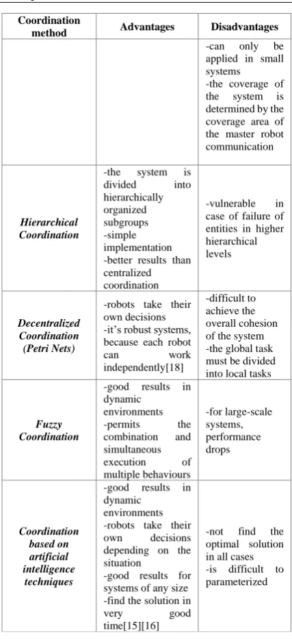
In Table 1 we present a short survey of existing coordination techniques with application in MRS, showing the main advantages and disadvantages for each method.
TABLE I. COMPARISON BETWEEN COORDINATION TECHNIQUES APPLIED IN MRS
Coordination
method Advantages Disadvantages
Centralized Coordination -simple implementation; -master-slave system
-if the master fails, the system becomes inoperable
Coordination
method Advantages Disadvantages
-can only be applied in small systems -the coverage of the system is determined by the coverage area of the master robot communication
Hierarchical Coordination
-the system is divided into hierarchically organized subgroups -simple implementation -better results than centralized coordination
-vulnerable in case of failure of entities in higher hierarchical levels
Decentralized Coordination (Petri Nets)
-robots take their own decisions -it’s robust systems, because each robot
can work
independently[18]
-difficult to achieve the overall cohesion of the system -the global task must be divided into local tasks
Fuzzy Coordination
-good results in dynamic
environments -permits the combination and simultaneous execution of multiple behaviours -for large-scale systems, performance drops Coordination based on artificial intelligence techniques
-good results in dynamic
environments -robots take their own decisions depending on the situation
-good results for systems of any size -find the solution in
very good
time[15][16]
-not find the optimal solution in all cases -is difficult to parameterized
Analyzing survey from Table 1 we can choose the appropriate coordination method for MRS depends on application environment and number of the MRS entities. For small MRS with low environment constrains, centralized coordination or Hierarchical Coordination can be a good choice and fast to implement.
In dynamic environments with large scale MRS the best results will be driven using Decentralized Coordination, for example using PetriNets approach in design a coordination method for a flexible manufacturing production line, topic that will be present in Cap. III and IV in this paper.
III. PETRI NETS COORDINATION MECHANISM
A. Introduction
Petri nets can give the solution to this problem as an effective tool for describing process specifications and developing control algorithms of discrete event systems.
For large scale systems with multiple robot systems interconnected, the PN network becomes very complicated and impossible to read and use. In that case is needed a simplified model of the network, model that will be used to program the robot cells controllers and interactions between system elements.
Next in this paper I’ll present a Petri net-based approach for coordination the robot cells of a complex beverage production line.
B. Petri Nets Fundamentals
A Petri net comprises two types of nodes, places representing conditions (or states) and transitions representing events, which are interconnected by directed arcs. Tokens, which reside at the places, are used to indicate the instantiation of a state.
PN’s [10] represents a modelling tool that can be applied into a variety of fields and systems, especially for systems with concurrent events. Murata presents in paper “Petri nets: Properties, analysis and applications” [9] a very good definition of the most important aspects of the theme.
Murata [9] define PN as a 5-tuple (P, T, F, w, M0), where:
P = {P1, ..., Pm} represents a finite set of places;
T = {t1, ..., tn} represents a finite set of transitions;
F (P T) (P T) represents a set of arcs;
w: F {1, 2, ...} represents the weight function;
M0: P {0, 1, 2, ...} represents the initial marking;
with (P T) = and (P T) .[10]
Using this representation, system can be represented as a Petri Net where states can be associated to places and marks (also called tokens), and events to transitions.
Definition [9]: “A transition t is enabled if each input place Pi t is marked with at least w(Pi, t)
tokens, where w(Pi, t) represents the weight of the arc between Pi and t.”
Once the transition t is enabled, a transition will fire when its associated event occurs.
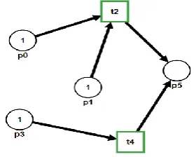
Graphical notation for PNs, presented in Fig.1, represents a very useful way to describe a PN, notation that will be used in the examples throughout this paper.
Using graphical representation, places will be represented as a circle, transitions as a rectangle, and tokens as dots, and arcs will be represented as an arrow that indicates the flow of the token, each arc will have above a notation of the weight. By definition, an unlabeled arc has weight=1.[10]
Fig. 1. PetriNet graphical and mathematical notations
Mathematical description of PN P={P0, P1, P2, P5}
T={t2, t4}
F={(P0,t2), (P1,t2), (P3,t4), (t2, P5),(t4,P5)} w(P0,t2)=w(P1,t2)=w(P3,t4)=w(t2,P5)= =w(t4,P5)=1
𝑀0=[1 1 1 0]τ
Using the graphical representation other advantages of using PNs is revealed: their support for system analysis. This analysis is based on the properties of the mathematical model and have the nest properties:
- Reachability: is the properties that the sequence reaches a given state [10].
- Liveness: is the properties that indicates if it is any state or sequence of states which will not be reached anymore, indicating a possible deadlock [10]
- Reversibility: indicates if is possible to return to a defined initial state M0[10]
- Boundness: indicates if a place will be overloaded [10]
- Persistence: indicates if is any pair of enabled transitions is interdependent10]
The actual state of a PN is described by the distribution of tokens, in the net. Gate arcs and output arcs represents the interface between the input and output of the process and connects a transition with a status signal source, and depending of the state of signal, it either start or stop an event.
External arcs are connected to the transitions of the net when needed, an example can be to synchronize and coordinate the movement of two mobile robots.
An output arc connects a place with an external machine signal and sends a command that enable an machine operation, for example a start movement command for a conveyor system.
When a token enters a place that represents a subtask, the machine code is informed to execute a subtask with specified parameters [20]. For multiple sequence control of discrete event robotic systems, the axioms of nets are as follows [20]:
1)A transition is started, only if the following conditions are fulfilled:
• output places have no token
• not have any internal permissive gate arc signaling 0 nor any internal inhibitive arc signaling 1; [20]
2) “A validated transition is started only if does not have any external permissive arc signaling 0 nor any external inhibitive arc signaling 1”.[20]
3) “When an enabled transition starts, the marking is changed to the new one, where each of its input places has no token and each of output places has one token.” [20]
A source transition is defined as a transition without any input place and one without any output place is defined as a sink transition, in other words a source transition can be enabled without any conditions done and a sink transition consume a token and not produce any token.
According to these axioms, the maximum number of tokens in each place never exceeds one, thus, the net is essentially 1-bounded and said to be a safe graph [20].
A conflict is defined as a transition with two or more input transitions and in this case is needed a set of arbitrations rules to conditioning the transition starting sequence.
A challenge using this is to obtain the flexibility demanded by the coordination mechanism of cooperative activity represented by the interaction between partners. In other words, coordination policies can be different depending on cooperation instance. Therefore, it is needed that coordination mechanisms to be flexible enough to handle these variations. [10]
This paper presents a coordination mechanism based on PNs that can be used in coordination of MRS in particular workflow environment, a flexible, full automated production line.
In this case we need to create a single coordination mechanism capable to manage all possible event by extracting the task form the production workflow.
In order to model the proposed coordination mechanisms, in this paper we use an approach based on Petri Nets (PNs), because of the advantages of graphical representation of PNs that offer a good details encapsulation, clear hierarchical model that makes the creation of coordination mechanism an easy task.
Petri Nets mechanism offer a good theoretical support for the analysis of a system evolution and possibility to simulate the behavior of the entire system that makes possible to anticipate and test the behavior of multi-workflow environments before their implementation.
The coordination mechanism of the MRS is defined as a net model corresponding to the discrete event process represented by all machine operation.
The PetriNet is represented by the places that represents a state of the process, the transition that
represents the operation task of each robot cell and all is connected by transition arcs in specific order defined by the process flow of each workpiece from raw material to finite workpiece.
For example the robot cell structure can be, the structure presented in Fig.2.The cell is structured into a set of physical workplaces that is represented by an infeed conveyor and outfeed conveyor used for transport of workpiece and the main robot that perform the modification of the state of workpiece and two buffer area used for deposit the workpieces.
Fig. 2. Configuration of robot cell structure
The robot cell is defined by the following tasks: 1. The workpieces is loaded in machine from buffer area 1 with conveyor 1;
2. The workpieces is processed by the palletizer robot and pallet is formed with a specific number of workpieces;
3. The pallet is transported with conveyor 2 into buffer area 2;
The robot cell can be represented by the following PetriNet, presented in Fig.3:
Fig. 3. PetriNet representation of robotic cell
The infeed buffer area 1 is represented by place m1. Loading the workpieces into the machine is represented by the transition T1.
The palletizer robot infeed area is represented by place m2.
The palletizer robot movement is represented by transition T2.
The pallet forming place is represented by place m3.
Unloading the pallet from machine is represented by transition T3.
The PN of the robotic cell can be defined by the 6-tuple (P, T,t, F, w, M0), where:
-the set of places P is defined:
P={m1,m2,m3,m4} -the set of transitions T is defined:
T={T1,T2,T3}
-the set of arcs F is defined: F={(m1,T1),(
T1,m2),(m2,T2),(T2,m3),(m3,T3),(T3,m4)} -the weight function is defined:
w: F {1, 2, ...} w(m2,T2)=x
x=number of workpieces needed for complete 1 pallet unit
w(m1,T1)=w(T1,m2)=w(T2,m3)=w(m3,T3)= =w(t3,m4)=1
-the initial state is defined: M0 =[1 0 0 0]
Starting from this we can define the tasks for the machine controller:
Task1: Move workpiece from m1 to m2
Task 2: Wait until the number of workpieces is equal with the number required for pallet layer
Task3: Put layer from m2 on the pallet location m3 Task4: Wait until the number of layers is the number required
Task5: Move pallet from m3 to m4
In Fig.3 is presented the logic diagram of the controller task, which can be used for programming any type of controller.
Fig. 4. Logic diagram of robotic cell
Complex multiple robot systems involve tasks that require coordination of multiple robots in the same time. In this case, a subtask calls for the cooperation of two or more robots, the local controller have to be involved to ensure proper execution of that subtask [20]. A possible communication and control structure for synchronization of two robots’ tasks is shown in next figure.
Fig. 5. Mutual communication and control of two robots
IV. CASE STUDY OF COOPERATIVE MULTI-ROBOT SYSTEM COORDINATION:PNCOORDINATION MECHANISM FOR AUTOMATED BEVERAGE PRODUCTION
LINE USING THE TEMPLATE
First case study presents a model of a flexible manufacturing system using PNs. The model describes the process of making carbonated beverages, each station being represented by a cooperative robot.
The goal of the model proposed for coordination of the robots is to optimize the flow of the process and synchronize the robots that forms the production system.
First of all, we need to make sure that the manufacturing system is supply with raw materials. In this process the raw materials are represented by water, sugar, syrup and PET pellets.
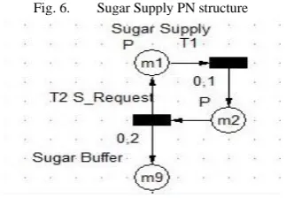
Each raw material supply station is represented by a PN and because all have the same structure, we will present only the sugar supply, that is represented by the PN in the Fig. 6:
Fig. 6. Sugar Supply PN structure
The PN of raw material supply station can be defined by the 6-tuple (P, T,t, F, w, M0), where:
P={m1,m2,m9} T={T1,T2}
F={(m1,T1),(m2,T2),(T1,m2),(T2,m1),(T2,m9)} w(m1,T1)=w(m2,T2)=w(T1,m2)=w(T2,m1)= w(T2,m9)=1
t(T2)=0,2 h = 720 s M0 =[1 0 0]
The first transition represents the transfer point between the sugar hopper and the sugar conveyor. The time for this transition is 0,1 h, time needed to load a batch of sugar.
The second transition is represented by the transfer of sugar between the hopper and sugar buffer tank. This action needs 0,2 h to transport the batch to the buffer tank.
In order to avoid a bottleneck in the first mixing task we need to coordinate the equipment involved in raw material supply.
Fig. 7. First Mixing PN structure
We see in the “First Mixing” transition two batch of water, two batch of sugar and one batch of syrup. As we can see in Fig.4 the water supply is a continuous supply, sugar supply needs 0,3 h/batch and syrup supply needs 0,4h/batch. In this case we observe a bottleneck on transition “First Mixing”. In order to avoid this, we need to increase the set point for processing speed of the sugar supply equipment.
ts1=0 (1)
ts2=t(T1)+t(T2) (2)
ts3=t(T4)+t(T5) (3)
ΔXe2[%]=𝑤(𝑚8,𝑇3)∗𝑡𝑠3
𝑤(𝑚9,𝑇3)∗𝑡𝑠2∗ 100
(4)
Ve2=V0e2+ V0e2* ΔXe2[%] (5)
where:
ts1, ts2, ts3 are the total time needed for processing one batch of raw material for each equipment
ΔX are the speed correlation factor between the process flows
V is the current speed of the equipment in batches/h.
The global task, First Mixing, we will split in subtasks for each stream:
For Water Supply:
WT1: Prepare treated water WT2: Send water to water buffer WT3: Waiting for request For Sugar Supply: ST1: Dissolve sugar
ST2: Prepare pasteurized sugar ST3: Send Sugar to sugar buffer
ST4: Waiting for request For Syrup Supply:
SyT1: Unload syrup barrel SyT2: Send syrup to syrup buffer SyT3: Waiting for request
In Fig. 7 is represented the logic diagram for the global task “First Mixing”.
As we can see in Fig. 7 robots of each stream needs to wait an undefined amount of time, until all the rest fulfill the request. In case of a flexible manufacturing line this unknown waiting time can be a problem because the lack of synchronizations between the raw materials flow.
In order to synchronize the robots, we will include a new task, synchronization, for each robot with the following subtasks:
T1: Prepare data- the robot measures the time needed to prepare the required amount of raw material.
T2: Send Data - the robot sends to all others the value from T1
T3: Receive data- the data from all others robots is received
T4: Compare data- actual speed is compared with the data received and the speed setpoint is adjusted
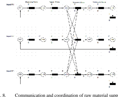
In Fig. 8 is represented the PetriNet coordination method for a 3-way raw material supply of the first mixing.
Fig. 8. Communication and coordination of raw material supply robots
Next is presented the mathematical representation of the coordination PetriNet from Fig.6.
Robot 1 – (Pr1, Tr1, Fr1, wr1, M0r1)
where:
Pr1= {IN1,,m2,m3,m4,m5,} Tr1={T1,T2,T3,T4,RN1}
Fr1={(IN1,T1),(m2,T2),(m3,T3),(m3,T7),(m3,T11) ,
(m4,T4),(m5,RN1)} wr1( Fr1)=1 M0r1={1, 0, 0, 0, 0}
PN of Robot 2 – (Pr2, Tr2, Fr2, wr2, M02) where:
Fr2={(IN2,T5),(m9,T6),(m8,T7),(m8,T3),(m8,T11) ,
(m7,T8), m6,RN2)} wr2(Fr2) =1 M0r2={1, 0, 0, 0, 0}
PN of Robot 3 – (Pr3, Tr3, Fr3, wr3, M03) where:
Pr3= {IN3,m10,m11,m12,m13 } Tr3={T9,T10,T11,T12,RN3}
Fr3={(IN3,T10),(m10,T10),(m11,T11),(m11,T3), (m11,T7),(m12,T12), (m13,RN3)}
Wr3(Fr3) =1 M0r3={1, 0, 0, 0, 0}
TABLE II. TRANSITIONS FIRING SEQUENCE
Time 1 2 3 4 5
Fire transition
1,5,9 2,6,10 3,7,11 4,8,12 RN1, RN2, RN3 Place
with token
2,9,10 3,8,11 4,7,12 5,6,13 IN1, IN2, IN3
Using PetriNet reachability analysis and simulation is possible to test some important properties of the system described in this paper such as: liveness, exclusion of deadlock, conservativeness of resources, boundedness ad reversibility.
When the “First Mixing” transition is complete the process moves forward to “Final Mixing” Step when the product is carbonated.
The chemical relation for carbonation process:
H2O(l) + CO2(g) H2CO3(aq) ( 6)
When the carbonation process is finishing the product is stored inside the “Product Buffer”, place M14. In Fig. 5 is presented the PetriNet of the filling process. This process combined two production flows, one represented by juice production and one represented by PET forming process. The problem is to coordinate and synchronize these two processes in order to achieve global performance of PET filling process.
Fig. 9. PET Filling PN structure
The synchronization between the equipment is presented by the next relation:
𝑃𝑟𝑜𝑑𝑢𝑐𝑡 𝑓𝑙𝑜𝑤 [m3
ℎ] = Filling_speed[
bottles h ] ∗ Bottle_volume[m3] (7)
From this point the coordination type is master-slave, the filling machine is the master and coordinates the speed of all the rest of the machines by giving to them the speed reference. The filler knows the status of each slave machine and in case of a malfunction adapts the speed in order to maximize the efficiency.
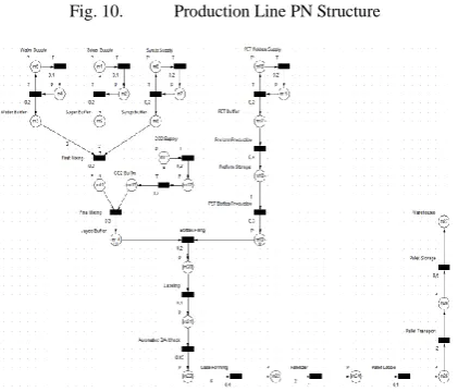
Fig. 10. Production Line PN Structure
This case study shows how we can use PN in a large scale MRS in order to achieve a coordination mechanism between the system entities. The qualitative approach of the method is focused on the logical level and is based on supervisory control of discrete events represented in model by the transitions.
In conclusion, we can say the PN coordination method is a good approach in coordination of large scale MRS, like a flexible beverage production line, giving a simple representation and control of the system and the interactions between the system entities.
CONCLUSION
The most important factor that influence the effectiveness of the coordination techniques is the environment in which MRS evolves. The best results until now for dynamic environments is achieved with decentralized coordination.
Using Petri Nets for developing the coordination mechanism and furthermore the control algorithm of decentralized controller of robot cells of a flexible production line has proven to be a very effective approach due to PN’s representation which offer an abstractisation and structure representation of the process necessary for MRS control.
REFERENCES
[1] E. Cardarelli,V.Digani, L.Sabattini,C.Secchi, C.Fantuzzi Cooperative cloud robotics architecture for the coordination of multi-AGV systems in industrial warehouses, In Mechatronics Volume 45, pages 1-13, 2017
[2] H. Costelha and P. Lima, “Modeling, analysis and execution of robotic tasks using Petri nets”, Proceedings of IEEE Int. Conf. on Intelligent Robots and Systems, San Diego, USA, pp. 1449-1454, 2007.
[3] M. S. Couceiro, R. P. Rocha and N. M. F. Ferreira, "A Novel Multi-Robot Exploration Approach based on Particle Swarm Optimization Algorithms," in IEEE International Symposium on Safety, Security, and Rescue Robotics, SSRR2011, Kyoto, Japan, 2011.
[4] J. L.Fernández, R.Sanz, E.Paz Domonte, C. Alonso, Using hierarchical binary Petri nets to build robust mobile robot applications: RoboGraph, IEEE International Conference on Robotics and Automation, 2008
[5] L. E. Holloway, B. H. Krough, and A. Gina, “A survey of Petri net methods for controlled discrete event systems”, Discrete Event Dynamic Systems, 7(2), pp. 151-190, 1997.
[6] D. Li, Q. Fan, and X. Dai, “Research status of multi-robot systems task allocation and uncertainty treatment”, ISAI 2017 – IOP Conf. Series: Journal of Physics: Conf. Series 887, 2017. [7] E.Kindler, R.Bergenthum, Algorithms and Tools for Petri Nets
- Proceedings of the Workshop, 2017
[8] M. Kloetzer and C. Mahulea, “A Petri net based approach for multi-robot path planning”, Discrete Event Dynamic Systems, 24(4), pp. 417-445, 2014.
[9] T. Murata, “Petri nets: Properties, analysis and applications”, Proceedings of IEEE, 77(4), pp. 541-580, 1989.
[10] A.B.Raposo, L.P.Magalhaes, I.M.Ricarte, Petri Nets Bases Coordination Mechanism for Multi-Workflow Environments,International Journal of Computer Systems Science & Engineering, 2000
[11] C.W.Reynolds. Flocks, herds and schools: A distributed behavior model. Comp. Graph. 21(4):25-34, 1987
[12] E.Sahin, S.Girnin, L.Baymdir, A.E.Turgut, Swarm Robotics, Merkle, D.: Swarm Intelligence: Introduction and Applications. Springer, Heidelberg (pp.87-100) 2008 [13] V.Sharma, K.Srinivasan, R. Kumar, H.C. Chao, K.L. Hua
Efficient cooperative relaying in flying ad hoc networks using fuzzy-bee colony optimization, In The Journal of Supercomputing Vol. 73, pag. 3229-3259, 2017
[14] W. Sheng and Q. Yang, “Peer-to-peer multi-robot coordination algorithms Petri net based analysis and design”, Proceedings of IEEE Int. Conf. on Advanced Intelligent Mechatronics, pp. 1407-1412, 2005.
[15] A.Sombat,T. Saleewong, P.Kumam Perspectives and Experiments of Hybrid Particle Swarm Optimization and Genetic Algorithms to Solve Optimization Problems In International Econometric Conference of Vietnam pag. 290-297, 2017
[16] P.Suarez, A.Galvez, A.Iglesias Autonomous Coordinated Navigation of Virtual Swarm Bots in Dynamic Indoor Environments by Bat Algorithm In International Conference of Swarm Intelligence pag. 176-184, 2017
[17] S. G. Tzafestas, Introduction to mobile robot control, Elsevier, 2014.
[18] Z. Yan, N. Jouandeau, A. A. Cherif: A Survey and Analysis of Multi-Robot Coordination, Advanced Computing Laboratory of Saint-Denis (LIASD), Paris 8 University, Saint-Denis, France, 2013
[19] Z. Yao, X. Dai, and H. Ge, “Quantitative and qualitative coordination for multi-robot systems”, in J. Lei et al. (Eds): AICI2012, LNAI 7530, pp. 755-761, 2012.