DOI: 10.22075/JRCE.2018.12347.1211
journal homepage: http://civiljournal.semnan.ac.ir/
Seismic Evaluation of Reinforced Concrete Moment
Frames Retrofitted with Steel Braces Using IDA and
Pushover Methods in the Near-Fault Field
A. Kheyroddin1,*, M. Gholhaki2 and Gh. Pachideh3 1. Professor, Faculty of Civil Engineering, Semnan University, Semnan, Iran
2. Associate Professor, Faculty of Civil Engineering, Semnan University, Semnan, Iran 3. Ph.D. Candidate, Faculty of Civil Engineering, Semnan University, Semnan, Iran
Corresponding author: [email protected]
ARTICLE INFO ABSTRACT
Article history:
Received: 29 August 2017 Accepted: 16 April 2018
One of the methods for seismic retrofitting in reinforced concrete structures is the application of steel braces. In this paper, the effect of concentric and eccentric bracing systems on the seismic performance of dual reinforced concrete building systems was inspected through seven near-fault earthquake records. Pursuant to that, two reinforced concrete frames with 10-story and 5 spans were designed and analyzed by means of the incremental dynamical analysis (IDA) method where the braces were placed in the 1st and 5th spans. The results revealed that the bearing capacity of the reinforced concrete frame by applying CBF and EBF braces increases up to 2.3 and 2 times, respectively. The use of EBF brace in a reinforced concrete frame reduces the amount of the base shear applied to the structure up to 7 times compared with the CBF frame. Approximately, the displacement of the roof in the EBF frame is less than the CBF frame. Moreover, the ductility of the EBF frame against earthquake records causes an increase in the performance level of structure to the immediate occupancy (IO).
Keywords:
Reinforced Concrete, CBF and EBF, Seismic Retrofitting, IDA,
Near-Fault.
1. Introduction
Seismic retrofitting is the modification of existing structures to make them be more resistant to seismic activity, ground motion, or soil failure as a result to earthquakes. This goal may be achieved by adopting one of the following strategies like by reducing the seismic demands on members and the
considerations/restrictions. Seismic retrofitting schemes can be either global or local, based on number members of the structures they are applied for global (Structural level) retrofit methods include conventional methods (increase the seismic resistance of existing structures) or non-conventional methods (reduction of seismic demand). In reinforced concrete buildings with moment frame and a shear wall needing reinforcement, one of the simplest methods requiring less damage to concrete surfaces and with faster runtime and better economic efficiency than other methods, is applying steel braces.
Two conventional methods are used for bracing reinforced concrete frames. In the first method, which is efficiently applied in important structures, the steel brace is first placed inside a steel frame, and consequently the brace and steel frame set is mounted inside the reinforced concrete frame with bolt and epoxy. In the second method, which is simpler, the steel brace is connected directly to the reinforced concrete frame by a metal crown or sheet and bolt. The second method is utilized in this paper.
In this paper, in order to investigate the nonlinear behavior of frames, reinforced concrete retrofitted with concentric (CBF) and eccentric (EBF) steel braces is applied.
2. History of Research
The study of reinforced concrete frames retrofitted by steel bracing is a relatively new topic and limited studies have been conducted in this field.
In 1990, Gould and Lee inspected the seismic strength of reinforced concrete retrofitted by concrete ductile steel braces [1]. In this study, a two-story reinforced concrete frame
damaged by the Mexican earthquake of 1985 was reinforced and constructed by steel braces and tested under reciprocating loads. The most noteworthy result of this experiment was the stability, the widespread hysteresis loop, and the high formability of the frame.
In 1994, Nateghi Elahi conducted a study on the seismic reinforcement of an eight-story reinforced concrete structure with steel braces. In this research, information was provided on reinforcement methods and considerations applied to strengthen the building for lateral and vertical loads [2].
In 1995, Maheri and Sahebi experimentally surveyed the reinforced concrete frames with steel brace. For this study, four samples of the frame were fabricated with one forth scale and tested for cyclic loading. The results of this study revealed that the final failure of the frame and the destruction of the stretched bracing are dominant on the frame behavior [2-3].
In 1997, Haji Ghaffari examined the interaction of steel frame and brace in reinforced concrete structures to withstand lateral forces. In this research, the effect of X and K shaped steel braces was explored on retrofitting the bending frame of a reinforced concrete without a shear wall. The results of this study exhibits that when applying steel bracing in a reinforced concrete frame, 0.1Fy allowable stress should be used to design steel braces, whereby braces can absorb 75% of the lateral force [4].
behavior of the structure and after a certain limit, it wouldn’t be beneficial in the behavior of the structure and shear absorption. The application of a combination of bracing and shear walls indicated better system behavior as well [5].
In 2001, kheyroddin and Shamkhali carried out a survey of eccentric braces behavior in existing reinforced concrete frames. The results of the study exhibits that eccentric bracing for 5-story reinforced concrete buildings was beneficial in all floors, while for 10 and 15-story buildings, the eccentric braces were effective in the lower floors structures up to e/L<0.5 (e is the length of the connecting beam and L is the length of frame span) and creates a negative shear in the last floors. The results also indicates that the ratios 0<e/L<0.25 is the best choice in terms of decreasing earthquake force and lateral displacements in all three types [6].
Maheri and Hadijpour, in 2003, arranged a laboratory program on straight cross-linked braces connected to the corners of the frame. In this research, they examining the method of bolting and binding sheets linked to concrete members and then welding the Gusset sheet to the beam and column joint sheets in three forms. Their research demonstrated that joining with hooked screws and planted in concrete and screws stretched to the other side of the member and supported by another sheet on that side, fitted well and increased stiffness. Furthermore, linking method by creating concrete chamfer in the corner of the frame has less hardness than the other two methods, and it is not recommended to apply it in view of the performance problems [7].
In 2008, Masoumi and Tasnimi explored the details of direct joints of bracing directly to
the concrete frame. In order to inspect the seismic behavior of reinforced concrete frames retrofitted with steel braces, a test program consisting of 8 concrete frame samples with a scale of 1 to 2.5 with identical details were designed. The samples consisted of two retrofitted frames as control of the samples and six braced frames and retrofitted applying 5 types of details in the connection between the frame and the brace. By reviewing, they concluded that among the five types of details of braces attached to the frame, the connection with the bolts and nuts increased to the beam and column increased the hardness of the frame, so that it could be claimed that this model is suitable for short-to-medium buildings. The bolt and nut connection to the column does not have much resistance and the loss of resistance is noticeable and can only be applied to boost in the early stages and such a detail does not seem appropriate. The attachment pattern in the form of a jacket without a glue is not suitable as a result to the slippage of the steel cover, however when the jacket is attached to the frame by the adhesive, as well as when the connecting element of the steel brace and the frame are inserted in an angle in the concrete, the frame performs better and absorbs more energy [8].
frames performance was appropriate for the case where the moment frames and braces were designed individually for earthquake forces [9].
In 2013, Masoumi and Absalan focused on the interaction between the concrete moment frames bracing system in a dual system. The results of this study exhibited a very good interaction between the two systems and the excellent performance of the dual system [10].
By studying the previous researches on the application of steel bracing in concrete frames and considering existing gaps, this study examined two 10-story reinforced concrete frames retrofitted with CBF and EBF braces. Each frame is subjected to seven earthquake records in the near-fault zone of varying intensity, and the displacement, drift, the base shear, and frames performance level will be compared.
3.
Retrofitting
Methods
for
Reinforced
Concrete
Moment
Frames with Steel Braces
In retrofitting of concrete structures, the method of connecting steel brace to the concrete frame is contemplated as one of the crucial items, so that the good function of bracing depends on how it is connected. The brace is connected to the reinforced concrete frame with both two methods direct and indirect [11].
3.1. Braced Steel Frame Enclosed in the Concrete Frame (Indirect Connection Method)
One of the ways to retrofit RC frames against lateral forces, and especially the earthquake, is the application of steel braces. Researchers on the retrofitting of such structures have
begun since the early 80's and in most cases, bracing has been indirectly applied by a steel frame enclosed in a concrete frame [11].
In the indirect method, the braces are positioned inside a steel frame and the steel frame is attached to the reinforced concrete frame in two ways. In the first method, if the concrete surface of the beam and the column of the concrete frame is flat and smooth, the steel frame is attached directly to the reinforced concrete frame by an epoxy or resin adhesive (Fig. 1.a). In the second case, a gap between the concrete and steel frames is initially created. Consequently, a series of bolt and slab reinforcement is planted inside the reinforced concrete beam and column. A series of slats or reinforcements are welded to the steel frame as well. Then, in place of the distance, a diphthong or spiral rebar is placed and finally, the gap is filled with grout or expanding mortar (Fig. 2.a). This action will increase the frame's strength significantly. This method is more suitable for concrete frames with lower concrete characteristic strength [11].
3.2. Direct Connection Method
a) Mode 1
b) Mode 2
Fig. 1. Indirect connection method
Fig. 2. Direct method of connecting steel braces to reinforced concrete frames [11]
4. Details of the Frames and Design
In this study, two 10-story reinforced concrete frames with five spans of 4 meters and a height of 3 meters are contemplated to be retrofitted by concentric (CBF) and eccentric (EBF) steel bracing in the first and last spans. Figure 3 reveals the overall view
of reinforced concrete frames retrofitted with steel braces. As a result of the applicability of the design, the dimensions and spans are real and structures are considered symmetrical. The application of the residential building and dead floor load, the partition equivalent load and the living load of floors and the ceiling are considered to be 650, 150, and 200 kg/m2, respectively.
a) Overview of concrete frame with a concentric brace (CBF)
b) Overview of concrete frame with an eccentric brace (EBF)
The compressive strength of the concrete frame 280 kg/cm2 and the yield strength of the main and rebar are 3000 and 2400 kg/cm2, respectively. The fourth edition of Iranian seismic code 2800 has been applied for loading and a quasi-static method for earthquake load, and first, the total base shear is computed and then distributed in the floors in proportion to weight. For the design of reinforced concrete members, the ACI Code, and the AISC Code for steel members have been used, respectively. The soil considered in this study is of type II.
For design, all frames were first designed in ETABS 2015 software, and after determining the sections of the beams, the columns were analyzed and evaluated in OpenSees software applying a brace (UNP section type).
The details of sections used in the design of frames are illustrated in Table 1.
Table 1. The details of sections used in the design of frames
Brace Section Beam Section Column Section Story
Number EBF CBF
2UNP180 2UNP160 80*70 80*80 1-2-3 2UNP140 2UNP140 70*60 70*70 4-5-6 2UNP120 2UNP120 60*50 60*60 7-8-9-10
5. Modeling Verification
In order to control the accuracy and make sure of the modeling and analysis process of frames, a one-story and one-span frame were modeled and verified with a frame examined by Masoumi and Tasnimi in 1997 [8].
208 four-noded elements were applied for modeling of desired moment frame where this element is suitable for beam members.
The earthquake forces were applied to a structure in 30 stages. Due to the smooth
stress behavior of the frame, each element is included in only one layer. In general, as a result to the change in the thickness of columns and beams with foundation, 2 layers of concrete have been applied for the foundation. The height of the frame is 100 cm and the opening of the frame is 180 cm. The compressive strength of concrete used was 250 kg/cm2.
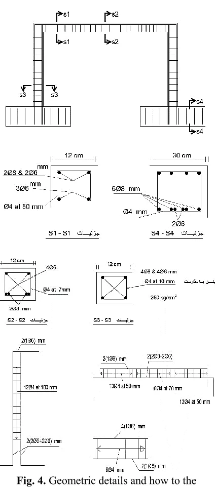
The geometric details and the method of reinforcing of the one-span frame tested by Masoumi and Tsennimi [8] are presented in Fig. 4.
After analyzing the structure, the comparison of numerical and experimental load-displacement plots for frames was presented in Fig.5.
As can be observed, the results are in good agreement.
For example, the experimental and numerical ultimate loads were equal to 15/4 and 14/4 KN, respectively. The ultimate load, acquired in an experimental program, were 7% higher than those in the numerical model.
steel behavior of the bars, materials of Steel02 have been used (Fig. 6.a), and Concrete01 materials for both enclosed (core) and unenclosed (coating) concrete (Fig. 6.B) [12] as well. The strain-strain curve of the enclosed concrete is computed pursuant the moderator model [13].
Fig. 4. Geometric details and how to the reinforcement of the one-span frame tested by
Masoumi and Tasnimi [8]
Fig. 5. Verification of numerical result with an experimental study
(a)
b)
Fig. 6. Stress-strain curve a) Steel and b) Concrete for modeling concrete elements [12]
6. Results of the Analysis of
Pushover Frames
reinforced concrete moment frames retrofitted with CBF and EBF steel braces is more than the reinforced concrete bending frame.
Fig. 7. Comparison of the frames pushover curve Furthermore, the yield capacity of the reinforced concrete moment frame is 20 KN and the yield capacity of the CBF and EBF frames is 55 and 60 KN, respectively. The maximum capacity of the concrete frame and the CBF and EBF frames are also 58, 135, and 120 KN, and from this value afterward, the structure begins to crack until it is
destroyed. With the reinforcement of concrete frame with the help of metal braces, the amount of frame displacement was reduced.
7. Non-Linear Analysis of Frames
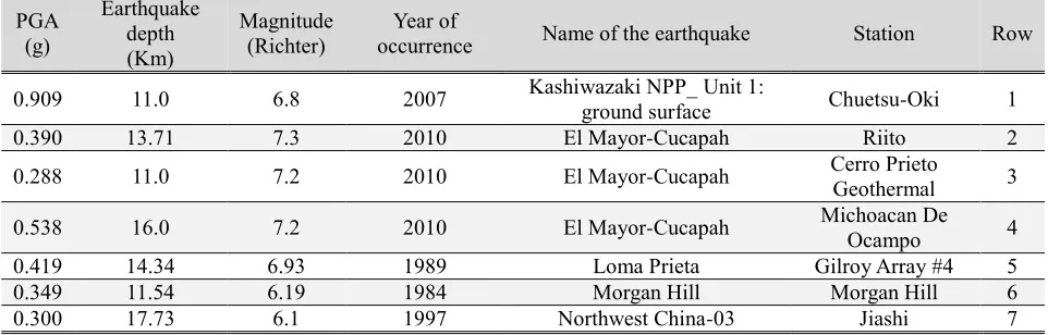
To achieve IDA analysis, 7 earthquake records in near fault-zone were considered according to table 2 in the peer website of the University of Berkeley
It should be noted that earthquakes whose occurrence distance are less than 15 km from the record station, is a near-fault field earthquake, and for distances exceeding 15 km, the earthquake is contemplated as the distant-fault area one. Consequently, two 10-story concrete frames with five spans retrofitted by the CBF and EBF metal braces in the first and last spans were subjected to the 7 Earthquake records under the Increasing dynamic analysis (IDA). The finite element analysis was performed by assuming the FiberSection model.
Table 2. Specifications of the records selected for the IDA analysis
Row Station
Name of the earthquake Year of occurrence Magnitude (Richter) Earthquake depth (Km) PGA (g) 1 Chuetsu-Oki
Kashiwazaki NPP_ Unit 1: ground surface 2007 6.8 11.0 0.909 2 Riito El Mayor-Cucapah 2010 7.3 13.71 0.390 3 Cerro Prieto Geothermal El Mayor-Cucapah 2010 7.2 11.0 0.288 4 Michoacan De Ocampo El Mayor-Cucapah 2010 7.2 16.0 0.538 5 Gilroy Array #4 Loma Prieta 1989 6.93 14.34 0.419 6 Morgan Hill Morgan Hill 1984 6.19 11.54 0.349 7 Jiashi Northwest China-03 1997 6.1 17.73 0.300
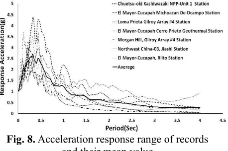
Each earthquake characterizes the site where the earthquake occurred, so the accelerometers applied should be scaled , in consonance tothe range of the study area. In order to scale the accelerometers, the accelerometers corresponding to the site
seismicity with the desired seismic response range, and then the scale factor is computed in such a way that the area under the curve of the earthquake response approximately matches with the design range within 0.1 to 4 seconds. The acceleration response range graph of all accelerometers considered along with their mean values are portrayed in Fig. 8.
Fig. 8. Acceleration response range of records and their mean value
8. Results and Discussion
After analyzing the structure in the OpenSees software, the drift curve for each earthquake record is indicated in Figures 9.a to 9.c.
The comparison of lateral drift with maximum allowable drift based on Iranian seismic code 2800 where is equal to 0.02 H (height of structure) for buildings with 5-story or more was indicated In Fig. 9. As revealed in this Fig., by applying the bracing system in reinforced concrete building all drifts were placed in within the allowable range.
a) Floors drift curve under the chuetsuoki0909g record
b) Floors drift curve under the elmayorcucapah0538g record
d) Floors drift curve under the elmayorcucapahriito039g record
e) Floors drift curve under the lomaprietagilroyarray0419g record
f) Floors drift curve under the morganhillgilroyarray0349g record
g) Floors drift curve under the northwestchina3jiashi03g record
Fig. 9. Floors drift curve under various earthquake records
As shown in Fig. 9.a, in general, under the earthquake record of chuetsuoki0909g, the drift of the frame with an EBF brace on all floors was more than the drift of the frame with a CBF brace, so that the largest drift has occurred on the seventh floor. The seventh-floor drift of the EBF frame is approximately 1.6 times the size of the CBF frame. Thus, in the earthquake record of the chuetsuoki0909g, the EBF frame is more ductile. In both frames from the seventh to tenth floors, the amount of drift is reduced, which this value is much higher in the EBF frame.
As indicated in Fig. 9.b, under the record of the earthquake elmayorcucapah0538g, the first-floor drift in both frames was approximately equal, but from the second floor it grew up and consequently in the EBF and CBF frames of the seventh and ninth floors afterward, the trend is decreasing. The largest amount of drift in the EBF frame is roughly 1.45 times the largest amount of drift on the CBF frame. On the tenth floor, the amount of drift in the CBF frame is less than the EBF frame, although this is the opposite
in the earthquake record of
elmayorcucapahcerroprieto0288g are slightly different from the two previous records. The CBF frame drift is more than the EBF frame up to the fourth floor and is reversed from the fifth to ninth floors, and again on the tenth floor, the drift of the CBF frame has become more than the EBF frame. Maximum drift occurred in CBF and EBF frames in the seventh floors, so that this value in the EBF frame is approximately 1.5 times of the CBF frame.
As portrayed in Fig. 9.d, under the
earthquake record of
elmayorcucapahriito039g, to the fifth floor, almost the drifts of the CBF and EBF frames are equal, however in the upper floors, the EBF frame drift is larger so that it reaches its maximum value on the eighth floor. The maximum drift of the EBF frame is about 1.5 times the maximum drift of the CBF frame, but they do not differ much on the tenth floor.
Pursuant to Fig. 9.e, under the lomaprietagilroyarray0419g earthquake record to the sixth floor, the drift of the frames is equal. The maximum drift occurred in the frames on the eighth floor and the drift of the EBF frame is about 1.3 times of the CBF frame.
Confirming to the Figure 9.f, under the record of the morganhillgilroyarray0349g earthquake in the CBF frame, with increasing floors, the drift does not change much and rises upright. However, in the EBF frame, the maximum drift occurred on the first floor, which is about 4 times the size of the CBF frame. Additionally, the drift of the EBF frame is more on all floors.
According to Figure 9.g, the northwestchina3jiashi03g earthquake record has the largest drift of frames on the 9th floor, which this value in EBF frame is
approximately 1.1 times the value of the CBF frame.
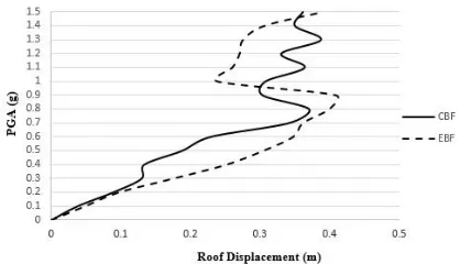
a) Earthquake severity-roof displacement curve under the Chuetsuoki0909g record
b) Earthquake severity-roof displacement curve under the elmayorcucapah0538g record
c) Earthquake severity-roof displacement curve under the elmayorcucapahcerroprieto0288g
d) Earthquake severity-roof displacement curve under the elmayorcucapahriito039g
e) Earthquake severity-roof displacement curve under the lomaprietagilroyarray0419g record
f) Earthquake severity-roof displacement curve under the morganhillgilroyarray0349g record
g) Earthquake severity-roof displacement curve under the Northwestchina3jiashi03g record
Fig. 10. Earthquake severity-roof displacement curve under different earthquake records Confirming to Figure 10.a, under the record of the chuetsuoki0909g earthquake with different severities, we can say that to the earthquake intensity of 0.8g, EBF and CBF frame roofing displacements increase and reach to 0.37 meters. From the earthquake intensity of the 0.9g to 1.5g, the roofing displacement did not change much in the CBF frame but reduced on the EBF frame. With an appropriate approximation, it is possible to say that the roof displacement of the two frames is equal in the intensity of 1.5g. With regard to Fig.10.b, under the earthquake record of elmayorcucapah0538g at all intensities, the displacement of the roof of the EBF frame was more so that when it reaches to the intensities of 0.5g and 1.5g, it is about 1.3 times the displacement of the CBF frame.
a more smooth behavior than the CBF frame. Pursuant to Figure 10.e, under the record of the earthquake lomaprietagilroyarray0419g with different intensities, up to the intensity of 0.4g, displacement of the roofs of the frames are equal and reach to the value of 0.34 with an equal slope. However, from the intensity of 0.5g to 1.5g, the CBF frame's roof displacement is more than the roof displacement of the EBF frame, and it traverses the graph vertically and with slight changes. Finally, at the intensity of 1.5g, the amount of roof displacement in the EBF frame is reduced.
According to Fig. 10.f, under the morganhillgilroyarray0349g earthquake record, the displacement of the roof of the CBF frame increases to the 0.4g intensity and then decreases sinusoidally. However, the displacement of the roof of the EBF frame increases to the 0.3g intensity and then shifts more smoothly and with greater steps than the CBF frame in a sinusoidal manner. Ultimately, at 1.5g intensity, the CBF frame roof displacement is about 2 times that of the EBF, indicating the optimal performance of the EBF frame against earthquakes.
Pursuant to Fig. 10.g, it can be concluded that under the northwestchina3jiashi03g earthquake record, the displacement of the roof of the two frames is almost identical and is steadily increasing. At last, the roof displacements reach to about 0.35 meters.
Consequently, in agreement to the results acquired from the Figures 10.a to 10.g, it can be stated that, up to the earthquake intensity of the 0.4g, the displacement of the roof of the two frames is equal, and then the EBF frame acts with a more smooth behavior than the CBF frame. Furthermore, as a result to the fact that in the CBF frames, the roof
displacement varies greatly and have fluctuating behavior, hence it has a lower level of safety and performance than the EBF frame against earthquake.
The comparison of the base shear in reinforced concrete moment frame with CBF and EBF braces were presented in Fig. 11. The columns with Nos. 1-6 are for the first story because frames were made 5 spans.
Fig. 11. Comparison of the base shear of the structure bottom columns
As portrayed in Fig. 11, the application of EBF brace in reinforced concrete moment frame can decrease the base shear up to 7 times. On that account, reinforced concrete buildings with EBF brace have the suitable performance compared to CBF brace. According to the assumptions contemplated, the use of the bracing system for retrofitting reinforced concrete moment frame increase the base shear.
9.
Comparison
of
Frames
Performance Levels
The vulnerability index based on the relative displacement of the floor was presented by Suzan in 1981, which is as follows:
(1)
DP = 25 (2 × %δ
H− 1)
In this relation: H is the height of the floor, δ is the floor relative displacement and DP is the percentage of damage.
The value of δ
H< 1% shows non-structural
damage (IO) and δ
H> 4% is unrecoverable
damage (LS) and δ
H> 6% shows structural
failure (CP) [14].
Moreover, one of the most popular indicators in the category of general indicators of the structure is the maximum relative displacement index computed from the following equation:
(2)
𝐷𝐼𝐷𝑅 =
∆𝑚
𝐻
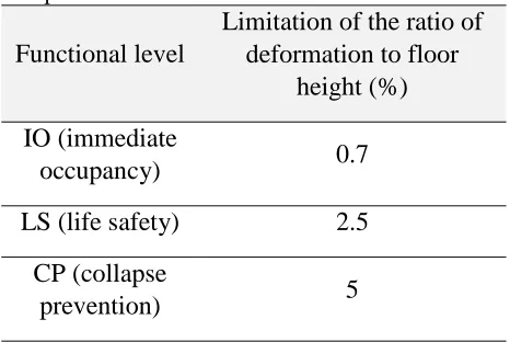
Where Δm is the maximum displacement of the roof (corresponding to the yield point) and H is the height of the structure. Table 3 indicates the dissimilar functional levels of the structure (based on FEMA356 instruction) and based on the relative displacement damage index.
Table 3. Limitation of maximum relative displacement index for different functional levels
Limitation of the ratio of deformation to floor
height (%) Functional level
0.7 IO (immediate
occupancy)
2.5 LS (life safety)
5 CP (collapse
prevention)
Therefore, pursuant to the results obtained from the performance levels of each of the frames under 7 different earthquake records, the CBF and EBF frames are at the level of IO and have the least damage to the frame.
10. Conclusion
In this paper, two reinforced concrete moment frames with a number of stories and spans of respectively ten and five were contemplated, which were retrofitted in their first and fifth spans with the application of CBF concentric steel frames and eccentric (EBF) steel bracing. Each of the frames was subjected to seven near-fault earthquake recordings, and the amount of drift, roof displacement and the base shear of each one were compared with each other, which yielded the following:
- The maximum drift of EBF and CBF frames was 0.025 and 0.007 respectively. Also, the minimum roof drift was 0.01 and 0.008 for these frames, respectively.
- In the eighth floor, each CBF and EBF frames reached its maximum. So the eighth floor was a sensitive and important floor.
- The roof displacement of the CBF and EBF frames is the same to 0.5 g earthquake intensity and displaces up to about 0.35 meters. However, in higher earthquake intensities, there was not much change in the displacement of frame roofs, but the EBF frame revealed a more smooth behavior.
- The use of steel bracing in the reinforced concrete moment frame reduces the base shear value up to 7 times when applied with CBF steel braces.
braces, the performance level the frames was within the limits of the immediate occupancy (IO), which indicates the proper reinforcement of these frames applying braces.
REFERENCES
[1] Goel, S.C., Lee, H.S. (1992). “Seismic Strengthening of Structures By Ductil Steel Bracing System“, Proceeding of Fourth U.S. National Conference on Earthquake Engineering, Vol.3, Canada. [2] Nateghi, A. (1995). "Seismic Strengthening
of Eight – Story R.C. Apartment Building Using Steel Brace", Engineering Structures; Vol. 17, No. 6, PP. 455- 461. [3] Maheri, M.R., Sahebi, A. (1995).
"Experimental Investigations of Steel Braced Reinforced Concrete Frames" Proceeding of the Second International Conference on Seismology and Earthquake Engineering; Vol. 1, Tehran Islamic Republic of IRAN: May 15-17, PP. 775- 784.
[4] Youssef, M.A., Ghaffarzadeh, H., Nehdi, M. (2006). "Seismic Performance of RC Frames with Concentric Internal Steel Bracing", Engineering Structures, Volume 28, Issue 13.
[5] Haji Ghaffari, H. (1997). "Interaction of steel frames and braces in reinforced concrete structures to withstand lateral forces". 5th Civil Engineering Conference of the Sharif University of Technology, Tehran, p. 228-238.
[6] Kheyroddin, A., Shamkhali Moghaddam, A. (2001). "Investigation of eccentric bracing behavior in existing reinforced concrete frames" Second International Conference on Tall Buildings, Iran University of Science and Technology, 143-152. (In Persian).
[7] Maheri, M.R., Hadijpour, A. (2003). “ Experimental investigation and design of steel brace connection to RC frame”, Engineering Structures.
[8] Massumi, A., Tasnimi, A.A. (2008). “strengthening of low ductile reinforced concrete frames using steel X-bracings with different details” The 14th world conference on earthquake engineering, 12-17, China.
[9] Godinez-Dominguez, E.A., Tena-Colunga, A. (2010). "Nonlinear behavior of code-designed reinforced concrete concentric braced frames under lateral loading". Engineering Structures, Vol. 32(4): pp. 944-963.
[10] Massumi, A., Absalan, M. (2013). "Interaction between the bracing system and moment resisting frame in braced RC frames". Archives of Civil and Mechanical Engineering, Vol. 13(2): pp. 260-268. [11] Kheyroddin, A., Sepahrad, R., Kafi, M.A.
(2016). “Investigation of laboratory behavior of reinforced concrete frames with cross-linked braces Steel”. 4th International Congress on Civil Engineering, Architecture and Urban Development. Shahid Beheshti University, Tehran, Iran. (In Persian).
[12] Mazzoni, S. (2007). "OpenSees Command Language Manual". College of Engineering, University of California, Berkeley.
[13] Mander, J., Priestley, M., Park, R. (1988). "Theoretical Stress‐Strain Model for Confined Concrete". Journal of Structural Engineering, Vol. 114(8): pp. 1804-1826. [14] Rahayi, A. Nemati, S. (2004). “Performance
![Fig. 2. Direct method of connecting steel braces to reinforced concrete frames [11]](https://thumb-us.123doks.com/thumbv2/123dok_us/8957666.1867034/5.612.360.493.225.412/direct-method-connecting-steel-braces-reinforced-concrete-frames.webp)