Volume 2, Special Issue 1 MEPCON 2015
57 Available online at www.ijiere.com
International Journal of Innovative and Emerging
Research in Engineering
e-ISSN: 2394 – 3343 p-ISSN: 2394 - 5494
Performance Investigation of Closed Loop Pulsating Heat
Pipe with Methanol as Working Fluid
Roshan D.Bhagat
1, K.M.Watt
21Student M.E.Thermal Engineering, Prof. Ram Meghe Institute of Technology & Research Badnera-Amravati, Sant
Gadge Baba Amravati University, India
2Department of Mechanical Engineering, Prof. Ram Meghe Institute of Technology & Research Badnera-Amravati,
Sant Gadge Baba Amravati Universit, India
ABSTRACT:
The closed-loop pulsating heat pipe is a small heat transfer device with a very high thermal conductivity. It can transfer sufficient heat for heat dissipation applications in modern electronic devices. The objective of this work is to study thermal performance of closed loop pulsating heat pipe with methanol as working fluid. Copper has been selected as material for heat pipe due to compatibility of copper with methanol as working fluid. Filling ratio of the working fluid significantly influence on the performance closed loop pulsating heat pipe. From the past studies it was observed that filling ratio of 30-75 % provides the best results. For this work 60 % filling ratio has been selected for this filing ratio the thermal performance of closed loop pulsating heat pipe with methanol as working fluid is investigated.
Keywords: closed loop pulsating heat pipe, condenser, evaporator, working fluid, filling ratio.
I. INTRODUCTION
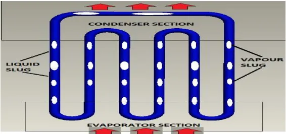
The closed-loop pulsating heat pipe is two phase passive thermal control device with a very high thermal conductivity. The Closed loop pulsating heat pipe is made of a long copper capillary tube, bent into an undulating tube and connected at the ends to form a closed-loop with no internal wick structure [1]. Working fluid is partially filled in the tube. The closed loop pulsating heat pipe has a condenser, evaporator section and adiabatic section. As any other two-phase passive thermal control device, heat is acquired from the source through the evaporator section transferring it to the working fluid where the slug/plug pumping action will be generated. The fluid then flows by the adiabatic section towards the condenser section. On a closed loop configuration, the fluid is allowed to circulate and after being condensed, the fluid returns to the evaporator section to complete the loop. The tube is evacuated and consequently partially filled with working fluid. Since an inner diameter of the tube is very small and then meets a capillary scale, the inside working fluid forms into liquid slugs alternating with vapour plugs along the entire length of the tube [2].
When one end of the closed-loop pulsating heat pipe, called ‘evaporator section’, is subjected to heat or high temperature, the working fluid, which is in liquid slug form, will evaporate, expand, and move through the no heat transferring zone, or ‘adiabatic section’, toward a cooler Section, ‘condenser section’ . Then, the vapour plugs will condense, collapse, and release the heat into the environment. Therefore, the vapour plug evaporating in the evaporator section will consequently flow to replace the vapour plug collapsing in the condenser section. Due to this mechanism, the working fluid can circulate and continuously transfer heat in a cycle. The structure of the closed loop pulsating heat pipe is as shown in Figure 1.
Volume 2, Special Issue 1 MEPCON 2015
58 Table 1: Compatibility of closed loop pulsating heat pipe material with the working fluid [2]
Working fluid Compatible Material
Methanol Stainless Steel, Iron, Copper, Brass, Silica, Nickel Acetone Stainless Steel, Copper, Brass, Silica
Table 2: Boiling point and operating ranges of working fluid [2] Working fluid Boiling point At 1 atm in K Temperature ranges in K
Acetone 329.4 273-393
Methanol 337.8 283-403
Ethanol 351.5 273-403
Figure 2: Experimental setup of closed loop pulsating heat pipe with methanol as working fluid
II. EXPERIMENTATION AND TESTING CLOSED LOOP PULSATING HEAT PIPE WITH
METHANOL ASWORKING FLUID
Table 3: Evaporator temperature of closed loop pulsating heat pipe with methanol as working fluid at variable heat input
Table 4: Condenser temperature of closed loop pulsating heat pipe with methanol as working fluid at variable heat input
Table 5: Thermal resistance of closed loop pulsating heat pipe with methanol as working fluid at variable heat input S.N VOLTAGE
(V)
CURRENT (A)
HEAT INPUT
(Watt)
CONDENSER TEMPERATURE OF METHANOL 𝐼𝑁0𝐶
AVERAGE CONDENSER TEMPERATURE
𝑇7 𝑇8 𝑇9 𝑇10 𝑇11 𝑇12
1 10 0.1 1 23.9 24 23.9 24 23.8 23.9 23.91666667
2 20 0.2 4 23.8 23.8 23.6 23.7 23.8 23.9 23.76666667
3 50 0.53 26.5 24 24 24.1 24.3 24.3 24.5 24.2
4 60 0.63 37.8 24.9 24.8 24.8 24.8 24.8 24.6 24.78333333
5 70 0.73 51.1 24.5 24.6 25.2 25.2 25.2 25.3 25
6 80 0.84 67.2 25.3 25.3 25.4 25.4 25.4 25.5 25.38333333
7 90 0.94 84.6 25.3 25.8 26 26 26 26.1 25.86666667
8 100 1.04 104 26.1 25.9 26.1 26 26 26.2 26.05
Volume 2, Special Issue 1 MEPCON 2015
59 S.N VOLTAGE
(V)
CURRENT (A)
HEAT INPUT
(Watt)
EVAPORATOR TEMPERATURE OF METHANOL 𝐼𝑁0𝐶
AVERAGE EVAPORATOR TEMPERATURE
T1 T2 T3 T4 T5 T6
1 10 0.1 1 24.9 24.9 24.9 24.7 24.7 24.9 24.83333333 2 20 0.2 4 24.4 24.5 24.5 24.5 24.5 24.5 24.48333333 3 50 0.53 26.5 28.4 28.7 29 29 28.9 28.9 28.81666667 4 60 0.63 37.8 30.8 30.9 31 31 31 30.9 30.93333333 5 70 0.73 51.1 33.2 33.1 33.1 33.1 32.9 32.6 33 6 80 0.84 67.2 35.6 35.7 35.7 35.5 35.5 35.1 35.51666667 7 90 0.94 84.6 38.5 38.6 38.6 38.7 38.6 38.4 38.56666667 8 100 1.04 104 41.1 40.8 40.8 40.3 40.3 39.5 40.46666667 9 165 1.73 285.45 70.8 70.8 70.8 70.4 70.4 70.4 70.6 10 175 1.77 309.75 71.6 71.6 71 70.8 70.5 70.2 70.95 11 185 1.95 360.75 71.9 70.7 71.4 72.2 72.4 72 71.76666667
S.N HEAT INPUT (Watt) FOR METHANOL
THERMAL RESISTANCE OF METHANOL
1 1 0.916666667
2 4 0.179166667
3 26.5 0.174213836
4 37.8 0.162698413
5 51.1 0.156555773
6 67.2 0.150793651
7 84.6 0.150118203
8 104 0.138621795
9 285.45 0.136159281
10 309.75 0.125961797
Volume 2, Special Issue 1 MEPCON 2015
60 Figure 3: Evaporator and condenser temperature of closed loop pulsating heat pipe with methanol
as working fluid at variable heat input
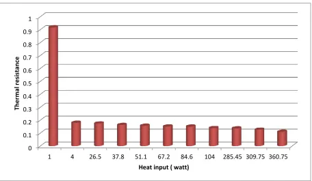
Figure 4: Thermal resistance of closed loop pulsating heat pipe with methanol as working fluid at variable heat input
III.CONCLUSIONS
The thermal resistance of closed loop pulsating heat pipe decreases with increase in the heat input. The closed loop pulsating heat pipe with methanol as working fluid having 60 % filling ratio capable of transferring more heat as heat input increases. Also the lower saturation temperature working fluids gives better performance.
REFERENCES
[1] H. Akachi, F. Polasek, and P. Stulc, “Pulsating heat pipes,” in Proc. 5th Intl. Heat Pipe Symp., Melbourne, Australia, 1996, pp. 208–217.
[2] M.B. Shafii, A. Faghri, Y. Zhang, Thermal modeling of unlooped and looped pulsating heat pipes, ASME J. Heat Transfer 123 (2001) 1159–1172.
[3] T. N. Wong, “High speed flow visualization of a closed loop pulsating heat pipe,” Heat Mass Transfer, vol. 48, pp. 3338–3351, 2005.
0 10 20 30 40 50 60 70 80
Tem
p
e
ratu
re
Heat input ( watt)
Evaporator
Condenser
0 0.1 0.2 0.3 0.4 0.5 0.6 0.7 0.8 0.9 1
1 4 26.5 37.8 51.1 67.2 84.6 104 285.45 309.75 360.75
Th
e
rm
al
r
e
si
stan
ce
Volume 2, Special Issue 1 MEPCON 2015
61 [4] N. Soponpongpipat, P. Sakulchangsatjatai, N. Kammuang-lue, and P. Terdtoon, “Investigation of the start up
condition of a closed loop oscillating heat pipe,” Heat Transfer Eng., vol. 30, no. 8, pp. 626–642, 2009. [5] Khandekar, S., Dollinger, N., Groll, M., “Understanding Operational Regimes of Closed Loop Pulsating Heat
Pipes: An Experimental Study”, 2003, Applied Thermal Engineering, Vol. 23, pp.707-719.
[6] T. Mallikharjuna Rao, Dr. S. S. Rao, Heat Pipes for Steam Condensation, IOSR Journal of Mechanical and Civil Engineering (IOSR-JMCE) e-ISSN: 2278-1684, ISSN: 2320-334X, Volume 11, Issue 2 Ver. I (Mar- Apr. 2014), PP 16-19.
[7] M. Groll, S. Khandekar, Pulsating heat pipes, Proceedings of the 3rd International Conference on Transport Phenomena in Multiphase Systems, Kielce, Poland, 2002, 35–44 (ISBN83-88906-03-08)
[8] S. Khandekar, M. Schneider, R. Kulenovic, M. Groll, Thermofluid dynamic study of flat plate closed loop pulsating heat pipes, Microsc. Thermophys. Eng. 6 (4) (2002) 303–318 (ISSN 1089-3954)
[9] Niti Kammuang-lue, Kritsada, Phrut Sakulchangsatjatai, Pradit Terdtoon, Correlation to Predict Thermal Performance According to Working Fluids of Vertical Closed-Loop Pulsating Heat Pipe, International Journal of Mechanical, Aerospace, Industrial and Mechatronics Engineering Vol:8 No:5, 2014
[10] Zhang, Y., Faghri, A., “Heat Transfer in a Pulsating Heat pipe with an Open End”, International Journal of Heat and Mass Transfer, Vol. 45, 2002, pp. 755- 764.
[11] Nagvase S.Y. and Pachghare P.R.Parameters Affecting the Functioning of Close Loop Pulsating Heat Pipe:A Review ISSN 2278 – 9472, Vol. 2(1), 35-39, January (2013)
![Table 2: Working fluid Boiling point and operating ranges of working fluid [2] Boiling point At 1 atm in K Temperature ranges in K](https://thumb-us.123doks.com/thumbv2/123dok_us/8874204.1815868/2.595.84.535.104.592/table-working-boiling-operating-working-boiling-temperature-ranges.webp)