A Defected Ground Based Rectangular Array
Slotted Microstrip Patch Antenna for C Band
Application
Basanta Paudyal1, Amit Kumar2, Bikram Bhandari3, Tejraj Giri4, Dharti Raj Shah5
M.Tech Scholar, Dept. of ECE, Swami Vivekanand Subharti University, Meerut, India1,3,4
Assistant Professor, Dept. of ECE, Swami Vivekanand Subharti University, Meerut, India2
Assistant Professor, Dept. of ECE, KNGD Modi Engineering College, Modinagar, India5
ABSTRACT: This paper defines, a Micro strip feed Microstrip Patch Antenna (MPA) operating at 4.1 GHz frequency with rectangular identical array slots is represented in this paper. Patch design was originally for lower resonating frequency and the resonating frequency was shifted by addition of slots to patch of MPA. The proposed antenna is designed using FR_4 epoxy substrate material having dielectric constant 4.4 and thickness 1.6 mm. This antenna has Reflection coefficient (S11) equal to -41.65dB. The performance parameters of antenna such as Voltage Standing Wave Ratio (VSWR), Return Loss (RL) and Radiation Pattern are simulated using High Frequency Structure Simulator (HFSS) software developed by Ansoft. Improved value of performance parameter of proposed antenna is achieved by defected ground and identical rectangular array slots at three different positions are cut on the patch.
KEYWORDS:Rectangular array slotted MPA for extended C band, microstrip feed, defected ground, identical slots, HFSS.
I.INTRODUCTION
A microstrip patch antenna consists of a dielectric substrate above which is a radiating patch and beneath it is a ground plane. MPAs are widely used in different wireless communication. Because of low cost, easy to manufacture, light in weight, easy integration with microwave circuits, low profile etc., MPAs are very popular now a days [1]. MPAs have wide application places where size and weight of antenna is to be reduced like space crafts, aircrafts, missiles, satellites and other portable devices. Poor efficiency, narrow bandwidth and low gain are some disadvantages of MPAs [2]. Bandwidth of the antenna can be changed by using different techniques. One of which is by using slots on the patch [3-4]. Another way to change bandwidth performance can be using low dielectric constant material with thick substrate [5]. However increasing thickness of substrate increases the size of MPA. Small sized MPA can be obtained by removing some specific slots from the radiating patch or the MPA. This paper has a rectangular MPA with microstrip feed. Identical rectangular slots at three different positions from the patch are removed. The size of ground plane is also reduced to achieve desired result. This antenna is proposed for extended C band downlink frequency in satellite communication application. C band in communication engineering is defined from 4 to 8 GHz [6]. Antenna excitation is done by microstrip feed. A suitable feed position and suitable thickness are used for impedance match[7]. Three slots are identical so dimensions are provided on separate slots in Antenna design, Results and discussion and conclusion of proposed MPA are mentioned below.
II.ANTENNA DESIGN
patch is C x C. Other dimensions are as shown in Fig1 and Fig2. All the three slots are identical in shapes. Slots and the defected ground plane provided in the proposed antenna optimize the performance of antenna at 4.1 GHz. This frequency falls in extended C-band of communication engineering. 3.7 to 4.0 GHz of C-band is used by satellites for downlinks.Proposed antenna feeding is done with microstrip feed with length Lf and width Wf. Proposed antenna has a defected ground of length Lf.
Fig.1. Top view of proposed antenna with parameters.
Fig.3 HFSS design
Table I. Design specification of proposed antenna
Parameters of antenna
Ls Ws H Lg Lf Wf Lp Wp A B C D E F
Dimensions (mm)
47 55 1.6 5 10 9.4 32 45 1 2 4 8 12 6.45
III.RESULTS AND DISCUSSIONS
The proposed microstrip antenna for C-band application is designed by selecting the optimal values of various above parameters. Microstrip feeding is done for the excitation of the patch antenna. In the parametric study optimal values of various above parameters are shown in Table I.
In the parametric study optimal values of each parameter was chosen and the remaining parameters were optimized by changing and testing their values. High Frequency Structure Simulator was used for simulation and testing of obtained results.
Firstly the size of the patch was calculated for the frequency lower than the required frequency. The width of the feed was optimized. First of all slot at the top right corner was cut out and it was seen that the resonating frequency shifted to a higher frequency. It was again optimized for better results. Then another slot at right top corner was created. Its position was shifted for optimum results. The result was again increase in resonating frequency. Then the last slot at bottom right corner was created which again increased the resonating frequency of the microstrip patch antenna to the required frequency of 4.1 GHz.
To remove other notches present in S11 result, again optimization were performed. The length of the ground plane was adjusted gradually for optimum results. All other notches gradually disappeared from S11result.
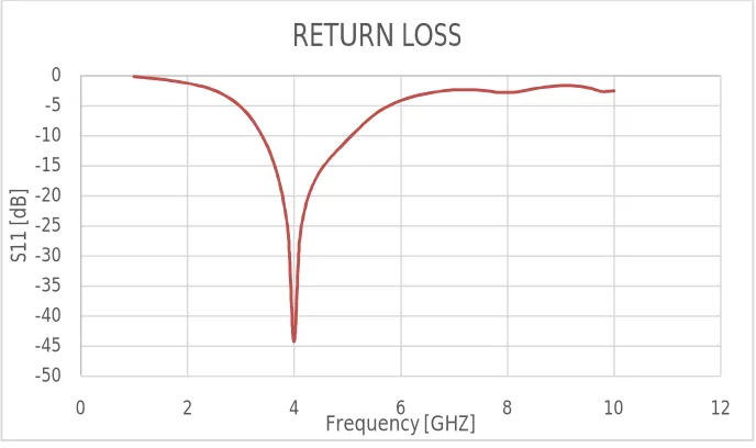
Fig.4. S11 v/s frequency plot of proposed antenna
Return loss or scattering parameters of the graph called as S-Parameters graph are used to measure the reflection and transmission losses between the incident and reflected waves [8]. Fig 4 shows the value of reflection coefficient or S11 which points at 4.1GHz.The value of S11 at the frequency 4.1 GHz is measured to be -41.65 dB. Its bandwidth at that frequency is measured to be 1.5 GHz. Other frequencies except the pass band are suppressed as shown in Fig3. This means that antenna is radiating in 4.1 GHz frequency band.
-50 -45 -40 -35 -30 -25 -20 -15 -10 -5 0
0 2 4 6 8 10 12
Fig.5. VSWR v/s frequency plot of proposed antenna at 4.1 GHz.
VSWR versus frequency plot of propose antenna is shown in Fig.5. Value of VSWR at resonating frequency 4.1 GHz is 1. VSWR which is a function of reflection coefficient describes the power reflected from the antenna. Value of VSWR should not exceed 2.
Radiation Pattern provides the information that how an antenna radiates and directs the energy in the desired direction. Radiation pattern of an antenna can be in polar or rectangular form. Two dimensional radiation pattern of the proposed antenna is shown in Fig.6. This radiation pattern is for resonating frequency at 4.1 GHz.Polar plot of the radiation pattern of the proposed antenna is shown in Fig.7 which is also for the resonating frequency at 4.1GHz.
Smith Chart for proposed antenna is shown in Fig. 8.
0 1 2 3 4 5 6 7 8 9 10
0 2 4 6 8 10 12
V
SW
R
Freq [GHz]
VSWR
Fig.7.3D-Polar Field Plot of proposed antenna at 4.1 GHz
Fig.8.Smith Chart of the proposed antenna at 4.1 GHz.
IV.CONCLUSION
In this paper, a rectangular microstrip patch antenna is proposed for C-Band downlink frequency application in satellite communication system. In the proposed design, there are three identical rectangular shaped array slots on the radiating patch which are used to shift the resonating frequency to the desired frequency of 4.1 GHz. Defected ground at optimal level, position and size of slots help to achieve optimum result at resonating frequency of 4.1GHz. The location of feed point is chosen for optimum results. The simulation on Ansoft HFSS showed optimum results.
REFERENCES
[1] S. S. Bhatia, J. S. Sivia, M. Kaur, “Comparsion of feeding techniques for the design of microstrip rectangular patch antenna for X-Band applications,” International Journal of Advanced Technology in Engineering and Science, vol.03, pp. 455-460, Feb 2015.
[2] Ashish Singh , Mohammad Aneesh, Kumari Kamakshi, Anurag Mishra, J.A. Ansari , “Analysis of F-shape microstrip line fed dualband antenna for WLAN applications,” Springer Science +Business Media New York 2013.
[3] Constantine A. Balanis , “Antenna Theory, Analysis and Design” (John Wiley & Sons).
[4] J.S.Sivia, S.S.Bhatia,“Design of fractal based microstrip rectangular patch antenna for multiband applications,”2015 IEEE International Advance Computing Conference (IACC), P.P 712-715.
[5] James, J. R. and Hall, P.S., “Handbook of Microstrip Antennas” (Peter Peregrines).
[6] Tajeswita Gupta and P. K. Singhal, “Ultra Wideband Slotted Microstrip Patch Antenna for Downlink and Uplink Satellite Application in C band,” International Journal of Innovation and Applied Studies, vol. 3, no. 3, pp. 680–684, July 2013.
[7] Indrasen Singh, Dr. V.S. Tripathi, “Microstrip patch antenna and its applications: a survey,” International Journal of Computer Technology and Applications vol. 2(5), pp. 1595-1599, sept-oct 2011.