Jurnal Teknologi, 44(A) Jun 2006: 27–40 © Universiti Teknologi Malaysia
SIMULATION OF A TWO-STROKE SPARK IGNITION FREE PISTON LINEAR ENGINE MOTION
N. A. N. MOHAMED1, A. K. ARIFFIN2 & S. FONNA3
Abstract. Two-stroke spark ignition free piston linear engine concept is analyzed in this paper. The main components of the engine are combustion chamber, scavenging chamber, kickback chamber and slider-piston. Dynamic and thermodynamic models of the slider-piston motion are presented. Also, the effect of various heat additions and compression ratio on the slider-piston velocity, time taken for one stroke, and stroke length are explored. By using selected engine variables, the motion of the two-stroke free piston linear engine is successfully simulated. The results show that the velocity profile of slider-piston motion is non-sinusoidal. By varying the amount of heat addition, the velocity and stroke length of slider-piston will increase accordingly. However, by increasing compression ratio, the velocity of slider piston is noted to increase but the stroke length of slider-piston remains constant.
Keywords: Free piston linear engine, two-stroke, compression ratio
Abstrak. Enjin linear omboh bebas dua lejang cucuhan bunga api dianalisis dalam kertas kerja ini. Komponen utama daripada enjin adalah kebuk pembakaran, kebuk hapus sisa, kebuk tending balik dan omboh. Model dinamik dan termodinamik bagi gerakan gelangsar-omboh dibentangkan. Seterusnya, kesan pelbagai nilai masukan haba dan nisbah mampatan terhadap halaju gelangsar-omboh dan panjang lejang juga diselidik. Dengan menggunakan parameter enjin yang dipilih, pergerakan enjin linear omboh bebas berhasil diselakukan. Hasil penyelakuan menunjukkan bahawa profil gerakan gelangsar omboh jauh dari bentuk sinus. Hasil penyelakuan terhadap pelbagai nilai masukan haba menunjukkan bahawa halaju dan panjang lejang gelangsar-omboh semakin tinggi dengan masukan haba yang semakin tinggi. Dengan semakin tinggi nisbah mampatan menyebabkan halaju gelangsar-omboh semakin tinggi manakala panjang lejang malar.
Kata kunci: Enjin linear omboh bebas, dua lejang, nisbah mampatan
1.0 INTRODUCTION
A free piston linear engine is a machine with linear motion as the primary motion. The crankshaft that normally present on a conventional reciprocating engine has been eliminated. This benefits in term of efficiency, weight reduction, robustness, variable compression operation and multi-fuel possibilities [1]. It also offers the potential to provide power without the conversion of linear to rotary motion [2].
1,2&3
The most common model has been developed based on the concept of free piston linear engine system with dual opposed combustion model [2-5]. This model has an advantage that the piston velocity profile is equal between the compression stroke and expansion stroke. Another model of free piston linear engine that has been developed are the models that replace a combustion chamber with other devices. A free piston linear engine that uses a spring as opposite to combustion chamber has been developed [6]. An air cushion chamber has been developed to replace one combustion chamber which is common free piston linear engines [7].
Nandkumar [2] has investigated the relationship between compression ratio, operating parameters such as air-fuel and load ratios, and stroke length for free piston linear engine consisting of two combustion chambers. It has been revealed that decreasing compression ratio implies decreasing stroke and due to the increase in heat input to the system, the instantaneous piston velocity increase so the time required for one cycle decrease.
This paper focuses on the analysis of a free piston linear engine that uses an air kickback chamber as the opposite to combustion chamber. The effects of various compression ratios and heat addition are also investigated. This work is important since to develop engine with the desired speed, an appropriate compression ratio and heat addition are needed.
2.0 DESCRIPTION OF MODELED ENGINE
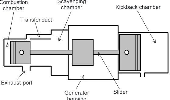
The description of the two-stroke spark ignition modeled engine is shown in Figure 1. It consists of five main parts, i.e. combustion chamber, scavenging chamber, kickback chamber, generator housing, and slider-piston. The term slider-piston is used to describe combustion piston, kickback piston, connecting rod, and permanent
Figure 1 Free piston linear engine model Combustion
chamber
Transfer duct
Scavenging
chamber Kickback chamber
Generator housing Exhaust port
magnet. The rod connects the two oppositely placed pistons and also acts as a prime mover of the linear engine. The permanent magnet is placed at certain position of the rod. The two opposed pistons have different diameter. The kickback piston diameter is larger than the combustion piston diameter. This is to ensure that the generated pressure in kickback chamber is adequate to pushback the slider-piston.
Free piston linear engine when coupled with linear alternator becomes a linear generator. When the slider-piston moves linearly, it will cause a disturbance to the field produced by the permanent magnet. As such, an electromagnetic force (EMF) will be induced in the coil of linear alternator. This is the principle of a free piston linear engine, i.e. to produce electricity directly from the linear motion of the pistons.
3.0 ENGINE DYNAMIC MODEL
The salient feature of free piston linear engine is a mechanically unconstrained piston [7]. Thus, the system obeys Newton’s second law.
2
2
ix i
d x
F m
dt
=
∑
(1)where Fix is the acting forces on slider-piston in x direction, m is the slider-piston mass, x is the instantaneous slider-piston position, and t is the time. The left hand side of Equation (1) represents the summation of the forces that act in the plane of motion, the right hand side of Equation (1) is the acceleration of slider-piston, and x
represents the displacement of slider-piston.
In order to analyze the slider dynamics, the forces acting on the free piston are determined. These forces are the combustion cylinder pressure, the scavenging pressure, the air kickback cylinder pressure, the piston ring-wall friction, and electromagnetic force. The forces balance on free piston is given by Equation (2) for after combustion condition and Equation (3) for after air kickback condition.
2
2
c c k k s s f e
d x P A P A P A F F m
dt
− − − − = (2)
2
2
k k c c s s f e d x
P A P A P A F F m dt
− − − − = (3)
where Pc is the instantaneous combustion chamber pressure, Pk is the instantaneous air-kickback chamber pressure, Ps is the instantaneous scavenging chamber pressure,
The engine is assumed running within no load condition, i.e. no power delivered. Thus, electromagnetic force is neglected in this simulation. According to Atkinson
et al. [5], the friction force is not significant for linear engine. Thus, it can be neglected since the force is relatively very small due to no crankshaft system. Figure 2 is given to illustrate a force balance on the free piston under simplified no load condition.
4.0 THERMODYNAMIC MODEL
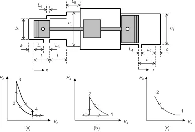
The compression and expansion of each cylinder is modeled adiabatically and internally reversible. The process in the combustion chamber is represented by the Otto cycle, while in the kickback chamber and the scavenging chamber by the ideal gas adiabatic process is as shown in PV diagrams in Figure 3. These processes occur simultaneously during expansion and compression stroke of the main combustion chamber. The schematic model of the engine is also described in Figure 3. The effects of intake and exhaust port length to the generated pressure in each chamber are also considered in the analysis.
For the initial condition, the slider is considered to move from left (combustion chamber dead point) to right in positive x direction i.e. expansion process. Here, the combustion chamber is chosen as reference. At these conditions, the pressure in the combustion chamber is Pc3 (as the result of instantaneous heat addition during combustion process), while the pressure in the kickback chamber and the scavenging chamber are free-air pressure (Pk1 and Ps1 respectively). When the slider moves to the right, the expansion process will follow 3-4 curve in PcVc diagram and at point 4 the exhaust port starts to open. Thus the pressure suddenly drops to Pc1 due to instantaneous heat rejection. The scavenging pressure will increase along the 1-2 curve in PsVs diagram and starting from point 2, the pressure will drop to Ps1 as the intake port start to open. While the kickback pressure remains at Pk1along L4 because of the port is still open and starting from point 1 in PkVk diagram, the pressure will increase following 1-2 curve.
Considering the slider moves from right to left after expansion stroke (i.e. compression stroke), the combustion pressure is Pc1 along L3 and the pressure will
Figure 2 Slider-piston free-body diagram
Ac
Pc
x As
m
Pk
Ak
increase (as shown by the 1-2 curve in PcVc diagram) starting from point 1. The kickback pressure will take the same path as the expansion stroke, while the scavenging pressure will remain at Ps1 along compression stroke.
In order to develop the pressure equations in each of the chamber, the processes involved are assumed to obey a polytropic process. The relationship between the pressure and the volume for the polytropic process is described by [8]:
n
PV =const (4)
The interdependence between the three thermodynamic properties – pressure (P), volume (V), and temperature (T) – is given by the state equation. State equations for various materials are determined either experimentally or theoretically. For ideal gases, the state equation is given by [8]:
PV =mRT (5)
where P is the gas pressure, V is the gas volume, m is the gas mass, R is the gas constant, and T is the absolute temperature. This is also known as the law of ideal gases. This law was initially established through experiments and subsequently it was also derived theoretically.
(a) (b) (c)
Figure 3 The dimension of engine: (a) pressure volume diagram for combustion chamber, (b) pressure volume diagram for scavenging chamber, (c) pressure volume diagram for kickback chamber
b1
L L
L3 L1
a
b3 L5 L4
x
L
c L2
x L4
b2
Vk
2
1
Pk
Vs
2
1
Ps
Vc
2
1
Pc
5.0 RESULTS AND DISCUSSION
5.1 After Heat Addition
Equations (6), (7), and (8) developed in this paper represent the pressures of each chambers which derived from Equation (4) and/or Equation (5). These equations respectively represent the combustion chamber pressure, the kickback chamber pressure, and the scavenging chamber pressure after combustion condition or for expansion process.
( )
(
()
)1
1 n
n in c c atm c
c
Q r n a
P P r
L a A a x
−
= +
+ +
(6)
( )
2 4
n n
k atm k
c
P P r
L L c x
=
+ + −
(7)
( )
( )
( )
( )
( )2 2
3 5 1
2 2
3 5 1
2 2
n
s atm
b L b L
P P
b L b L x
+
=
+ −
(8)
where Patm is the atmospheric pressure, rc is the compression ratio for combustion chamber, rk is the kickback chamber compression ratio, Qin is the heat addition to combustion chamber during combustion process, and n is the specific heat ratio as given in Table 1. Then, the force balance equation for expansion process taken from Equation (2) is given by:
( )
(
()
)( )
( )
( )
( )
( )
( )1 2 4
2 2 2
3 5 1
2 2 2
3 5 1
1
2 2
n n
n in c n
atm c c atm k k
c
n
atm s f e
Q r n a c
P r A P r A
L a A a x L L c x
b L b L d x
P A F F m
dt
b L b L x
− + − + + + + − + − − − = + − (9)
5.2 After Kickback
Equations (10), (11), and (12) represent the combustion chamber pressure, the kickback chamber pressure, and the scavenging chamber pressure after kickback condition, or for compression process.
( )
n nc atm c
a
P P r
a x
=
( )
2 4
n n
k atm k
c
P P r
L L c x
=
+ + −
(11)
s atm
P =P (12)
The force balance equation for compression process taken from Equation (3) is given by:
( )
−( )
{ }
+ + − +
+ − − =
2 4
2
2
n n
n n
atm k k atm c c
atm s f e
c a
P r A P r A
L L c x a x
d x
P A F F m
dt
(13)
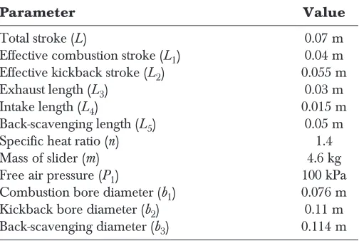
Table 1 Simulated engine specifications
Parameter Value
Total stroke (L) 0.07 m
Effective combustion stroke (L1) 0.04 m
Effective kickback stroke (L2) 0.055 m
Exhaust length (L3) 0.03 m
Intake length (L4) 0.015 m
Back-scavenging length (L5) 0.05 m
Specific heat ratio (n) 1.4
Mass of slider (m) 4.6 kg
Free air pressure (P1) 100 kPa
Combustion bore diameter (b1) 0.076 m
Kickback bore diameter (b2) 0.11 m
Back-scavenging diameter (b3) 0.114 m
In order to generate free piston simulation, some engine specifications have been chosen from the prototype engine, which developed as in [9]. These specifications are given in Table 1 and the compression ratio for combustion and kickback chambers are taken to as r, where rc = rk = r.
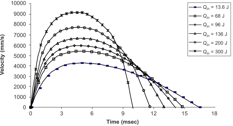
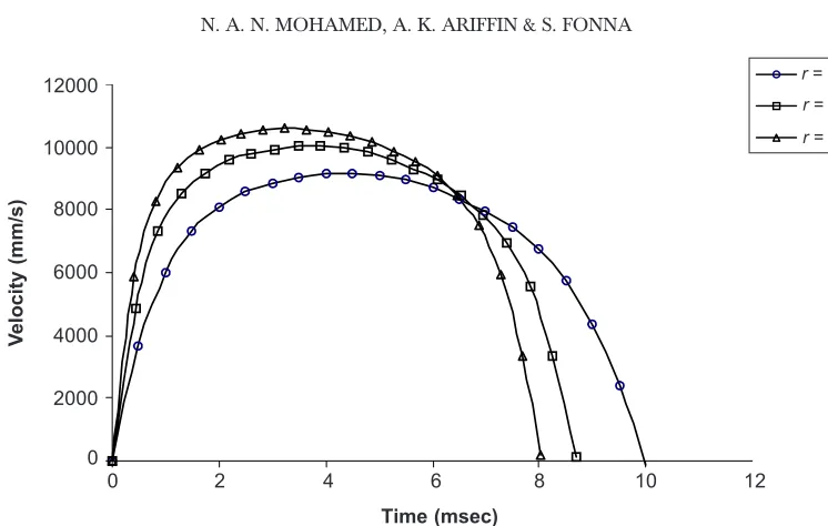
Figure 5 plots the slider-piston velocity versus stroke time for various heat addition. This figure shows that the maximum velocity of slider-piston is increased when the acceleration of slider-piston increases, since more heat is added to the system. The figure also shows that for the higher heat addition, the stroke time will be less. The relationship between the slider-piston velocity and the slider-piston position for various
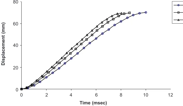
Figure 4 Piston position versus stroke time for various Qin
80
60
40
20
0
0 3 6 9 12 15 18
Displacement (mm)
Time (msec)
Figure 5 Piston velocity versus stroke time for various Qin
10000
0
V
elocity (mm/s)
Time (msec)
9000 8000 7000 6000 5000 4000 3000 2000 1000 0
3 6 9 12 15 18
Qin = 13.6 J
Qin = 68 J
Qin = 96 J
Qin = 136 J
Qin = 200 J
Qin = 300 J
Qin = 13.6 J
Qin = 68 J
Qin = 96 J
Qin = 136 J
Qin = 200 J
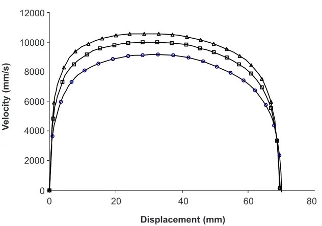
heat addition is illustrated in Figure 6. The figure gives a clear description that by increasing heat addition, the stroke length increases as the slider-piston velocity increase too.
The effect of various compression ratio on the stroke length is shown in Figure 7. The stroke length remains constant with the increase in compression ratio. The
Figure 6 Piston velocity versus piston position for various Qin
0
0 20 40 60 80
V
elocity (mm/s)
Displacement (mm)
10000
8000
6000
4000
2000
Figure 7 Piston position versus stroke time for various r
80
60
40
20
0
0 2 4 6 8 10 12
Displacement (mm)
Time (msec)
Qin = 13.6 J
Qin = 68 J
Qin = 96 J
Qin = 136 J
Qin = 200 J
Qin = 300 J
r = 10
r = 15
generated pressures/forces in each chamber, i.e. combustion chamber and kickback chamber are higher when the compression ratio is increased. This condition cause the stroke length to be unchanged. The increased pressure in the combustion chamber is compensated by the increased pressure in the kickback chamber. Thus, the slider-piston stroke remains constant for the various compression ratio. It also shows that the stroke time will be lower for the higher compression ratio since the increased pressure would increase slider-piston acceleration.
Figure 8 is a plot of the slider-piston velocity versus stroke time for various compression ratio. It is clear that the maximum velocity of slider-piston is increased when the acceleration of slider-piston increase since the compression ratio of system is higher. The figure also shows that for the higher compression ratio, stroke time is less than the lower compression ratio. The relationship between the slider-piston velocity and the slider-piston position for various compression ratio is illustrated in Figure 9. This figure shows a clear description that by increasing compression ratio for combustion and kickback chamber, the slider-piston velocity increase while the stroke length remains constant.
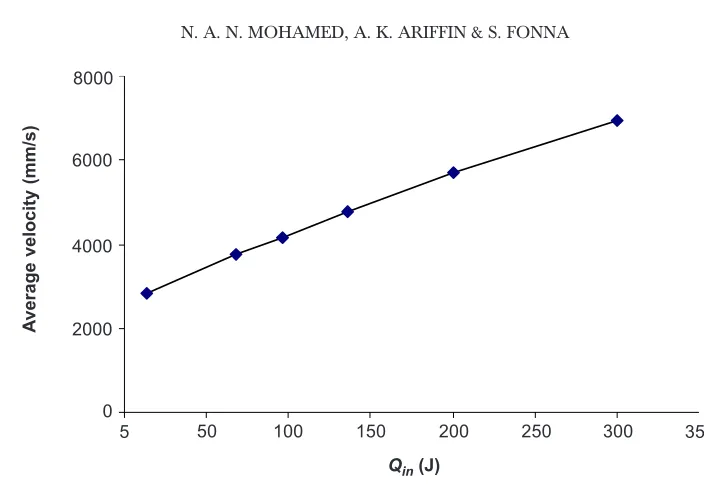
Figures 10 and 11 illustrate the effects of various compression ratios and heat additions to the average velocity of slider-piston. From the above discussion, it is clear that by increasing compression ratio of each chamber (i.e. combustion chamber and kickback chamber) and increasing heat addition in combustion chamber would increase the maximum velocity of slider-piston. Then, by deriving the average velocity of each condition, it shows that higher compression ratio and heat addition would ultimately increase the average velocity of the slider-piston. The result is important
Figure 8 Piston velocity versus stroke time for various r
0
0 2 6 8 12
V
e
locity (mm/s)
Time (msec)
12000
10000
8000
6000
4000
4 10
2000
r = 10
r = 15
in order to design an engine with appropriate compression ratio and to decide the appropriate amount of fuel for one combustion process.
These result show good compromise with the previous work by Nandkumar [2] although with different model. He clarifies that the increasing compression ratio will increase piston velocity and due to the increase in heat input to the system, the instantaneous piston velocity increase too.
Figure 9 Piston velocity versus piston position for various r
Figure 10 Piston average velocity versus compression ratio 0
V
elocity (mm/s)
12000
10000
8000
6000
4000
2000
0 20 60
Displacement (mm)
40 80
A
verage velocity (mm/s)
10000
8000
6000
4000
10 20
Compression ratio
15 25
5
r = 10
r = 15
6.0 CONCLUSIONS
The dynamic and thermodynamic model analyses of a free piston spark ignition linear engine have been presented. The velocity and displacement profiles of slider-piston motion with respect to time and velocity profile with respect to displacement are investigated for various heat additions and compression ratios. By varying heat addition, the velocity and stroke length of slider-piston will increase with higher heat addition. However, by increasing compression ratio, the velocity of slider piston increase but the stroke length of slider-piston remains constant.
ACKNOWLEDGEMENTS
The project was sponsored by the Malaysian Ministry of Science, Technology, and Innovation (MOSTI) under IRPA 03-02-02-0056 PR0025/04-03 grant mechanism.
REFERENCES
[1] Arshad, W. M., T. Bäckström, P. Thelin, and C. Sadarangani. 2002. Integrated Free-Piston Generator: An Overview. Proceeding of NORPIE/2002. Stockholm, Sweden.
[2] Nandkumar, S. 1998. Two-Stroke Linear Engine. M.Sc. Thesis. West Virginia University. Morgantown, West Virginia.
[3] Houdyschell, D. 2000. A Diesel Two-stroke Linear Engine. M.Sc. Thesis. West Virginia University. Morgantown, West Virginia.
[4] Goldsborough, S. S., and P. V. Blarigan. 1999. A Numerical Study of a Free Piston IC Operating on Homogeneous Charge Compression Ignition Combustion. SAE Paper: 1999-01-0619.
Figure 11 Piston average velocity versus Qin
A
verage velocity (mm/s)
8000
6000
4000
0
100 250
Qin (J)
200 350
5 50 150 300
[5] Atkinson, C. M., S. Petreanu, N. N. Clark, R. J. Atkinson, T. I. McDaniel, S. Nandkumar, and P. Famouri. 1999. Numerical Simulation of Two-Stroke Linear Engine-Alternator Combination. SAE Paper: 1999-01-0921.
[6] Annen, K. D., D. B. Stickler, and J. Woodroffe. 2002. Miniature Internal Combustion Engine (MICE) for Portable Electric Power. Aerodyne Research. Inc. Proceeding of 23rd Army Science Conference. Orlando, Florida.