Davoud Zarifi* and Marziye Nasri
Abstract—This paper presents a Ku-band filter based on groove gap waveguide (GGW) technology which is composed of a filter with two transitions GGW and WR-62. The filter is operated from 13.8 GHz to 14.2 GHz. Actually, a fractional bandwidth of about 2.85% is obtained for maximum return loss of 20 dB and the maximum insertion loss of 0.05 dB over the bandwidth. The validity of the design results is confirmed both numerically and experimentally. Measurement results show that the performance of filter agrees well with simulation. This filter could be used as part of a gap waveguide based structure.
1. INTRODUCTION
Filters are building blocks of many microwave and millimeter-wave components and networks for different applications. Waveguide and microstrip filters are known as the most common types of these components [1–3]. The use of hollow waveguides is critical in the design of millimeter-wave filters to eliminate the dielectric loss. However, at high frequencies, due to short wavelengths and small dimensions, the fabrication process of conventional waveguide components is a challenge.
Recently, manufacturing problems in mm-wave designs motivated the consideration of gap waveguide technology [4, 5]. Gap waveguide technology is based on parallel-plate waveguide configuration and using a periodic array of electromagnetic bandgap structure to control the direction of propagation. In fact, this technology overcomes the problem of good electrical contact associated with mechanical assembly in different microwave components especially at high frequencies [6–11]. There are many modern manufacturing technologies that can be used to produce planar surfaces with small texture, such as die sink Electrical Discharge Manufacturing (EDM), Electron Beam Melting (EBM), multilayer die pressing, and 3D screen-printing.
This paper presents a Ku-band GGW filter fed by a rectangular waveguide through a designed transition from GGW to WR-62.
The paper is organized as follows. Section 2 deals with the design of GGW structure with the desired bandgap. The performances of the filter and transition are discussed in Section 3, and the simulation and measurement results are presented in Section 4. Finally, Section 5 provides the conclusion.
2. GROOVE GAP WAVEGUIDE STRUCTURE
The geometry of the GGW is depicted in Fig. 1. In this structure, the field propagates inside a groove created within the textured surface of metal pins. Unlike ordinary rectangular waveguides, electrical contact between the walls of a GGW is not necessary.
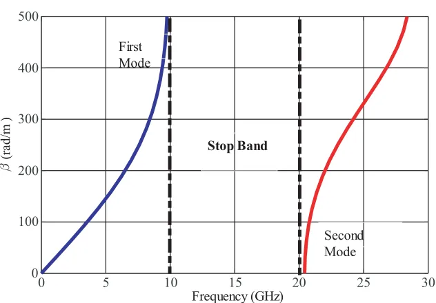
To achieve a stopband from 10 to 20 GHz, the dimensions of the pins and gap size should be appropriately selected. The pin dimensions are chosen according to the guidelines in [5]. Full-wave
Received 12 April 2018, Accepted 17 May 2018, Scheduled 29 May 2018 * Corresponding author: Davoud Zarifi ([email protected]).
0 5 10 15 20 25 30
Frequency (GHz)
0 100 200 300 400 500
(ra
d /m
)
First Mode
Second Mode Stop Band
Figure 2. Dispersion diagram of the unit cell of the periodic pins of GGW structure (a= 2 mm,d= 6,
p= 4 andg= 1).
simulation of the designed subarray is performed by using the time-domain solver of the CST Microwave Studio which uses a finite element method. The dispersion diagrams of an infinite two-dimensional pin array are calculated and shown in Fig. 2.
3. DESIGN OF KU-BAND FILTER AND TRANSITION 3.1. Filter Configuration
The geometric configuration and schematic diagram of the proposed bandpass filter are shown in Fig. 3(a). It consists of four cavities. The coupling strength among the cavities can be adjusted by the width of the inductive windows. The operating frequency is inversely proportional to the width and interspace of the inductive windows. In fact, some extra tuning pins are located near the side walls of the groove to provide the appropriate coupling among the cavities.
3.2. Transition
(a) (b)
(c)
Figure 3. (a) The Perspective of the proposed bandpass filter; (b) The geometry of transition from GGW to a rectangular waveguide (WR-62); (c) The geometry of the proposed bandpass filter.
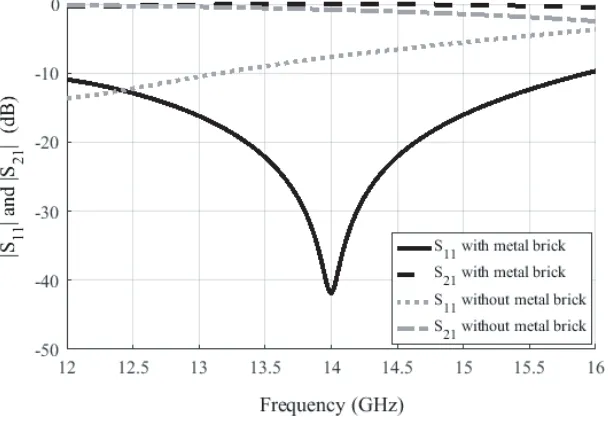
Figure 4. Reflection and transmission coefficient of transition from GGW to WR-62.
to WR-62. In this structure, a metal brick section with an extension to the waveguide opening is placed on the bottom wall of the GGW. For achieving the desired matching, parameters lt1, lt2, wt and ht should be optimized.
Figure 5. Simulated electric field distribution of the proposed transition at the center frequency 14 GHz.
4. SIMULATION AND MEASUREMENT RESULTS
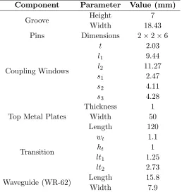
The final values of the overall structure dimensions shown in Fig. 3(c) are listed in Table 1. It is designed at 14 GHz with the aid of CST MWS. In addition, The simulation results are validated by experimental measurement. The overall view of the fabricated filter is shown in Fig. 6. The structure size is 120 mm×50 mm×10 mm. It was manufactured using standard milling machine techniques. The
Table 1. Design parameters of Ku-band filter.
Component Parameter Value (mm)
Groove Height
Width
7 18.43
Pins Dimensions 2×2×6
Coupling Windows
t l1
l2
s1
s2
s3
2.03 9.44 11.27
2.47 4.11 4.28
Top Metal Plates
Thickness Width Length
1 50 120
Transition
wt ht lt1
lt2
1.1 1 1.25 2.73
Waveguide (WR-62) Length
Width
Figure 6. Photograph of fabricated filter prototype.
13.6 13.8 14 14.2 14.4
Frequency (GHz) -50
-40 -30 -20 -10 0
|S 11
| a
nd
|S
21
| (
dB
)
S11(simulation) S21(simulation)
S11(measurement) S21(measurement)
Figure 7. Simulated and measured reflection and transmission coefficients of the proposed bandpass filter.
input reflection coefficient of the filter structure was measured by a mmWave band Agilent network analyzer. Fig. 7 shows the simulated and measured results of overall structure. Observe that within 13.8–14.2 GHz, the simulated reflection is less than−20 dB, and the insertion loss is less than 0.05 dB. Good agreement has been achieved between simulation and measurement. The differences between the measured and simulated results are because of the fabrication inaccuracies and assembling tolerances.
The electric field distributions inside the structure at frequencies of 14 GHz and 3.5 GHz are shown in Fig. 8. Observe that the electromagnetic wave propagates within the specified bandpass, but it is rejected at other frequencies.
and (b) 13.5 GHz.
5. CONCLUSION
A Ku-band filter has been proposed and demonstrated using the groove gap waveguide technology. In order to tune the resonant frequency of each resonator, the size of the cavities has been optimized. The simulated insertion loss of the designed filter is less than 0.05 dB in the band 13.8–14.2 GHz. The overall performance of the filter and transition is quite promising, and this can open up new development of such components in the future.
REFERENCES
1. Hunter, I. C., Theory and Design of Microwave Filters (Electromagnetic Wave), Ch. 1, IET, Piscataway, NJ, 2006.
2. Vahldieck, R. and W. J. R. Hoefer, “Finline and metal insert filters with improved passband separation and increased stopband attenuation,” IEEE Trans. Microw. Theory Tech., Vol. 33, No. 12, 1333–1339, Dec. 1985.
3. Hong, J.-S. and M. J. Lancaster, Microstrip Filters for RF/Microwave Applications (Microwave and Optical Engineering), Wiley, New York, 2001.
4. Kildal, P.-S., E. Alfonso, A. Valero-Nogueira, and E. Rajo-Iglesias, “Local metamaterial-based waveguides in gaps between parallel metal plates,” IEEE Antennas and Wireless Propagation Letters, Vol. 8, 84–87, 2009.
5. Kildal, P.-S., “Three metamaterial-based gap waveguides between parallel metal plates for mm/submm waves,” Proc. 3rd Eur. Conf. Antennas Propag., Berlin, Mar. 2009.
6. Zarifi, D., A. Farahbakhsh, A. U. Zaman, and P. S. Kildal, “Design and fabrication of a high-gain 60 GHz corrugated slot antenna array with ridge gap waveguide distribution layer,” IEEE Trans. Antennas Propag., Vol. 64, No. 7, 2905–2913, Jul. 2016.
7. Dong, X., H. Wang, F. Xue, and Y. Liu, “Design and measurement of a novel seamless scanning leaky wave antenna in ridge gap waveguide technology,” Progress In Electromagnetics Research M, Vol. 58, 147–157, 2017.
8. Zarifi, D., A. Farahbakhsh, A. U. Zaman, and P. S. Kildal, “A gap waveguide-fed wideband patch antenna array for 60-GHz applications,”IEEE Trans. Antennas Propag., Vol. 65, No. 9, 4875–4879, 2017.
9. Vosoogh, A. and P.-S. Kildal, “Corporate-fed planar 60 GHz slot array made of three unconnected metal layers using AMC pin surface for the Gap waveguide,” IEEE Antennas and Wireless Propagation Letters, Vol. 15, 1935–1938, 2015.
10. Alos, E. A., A. U. Zaman, and P.-S. Kildal, “Ka-band gap waveguide coupled-resonator filter for radio link diplexer application,” IEEE Trans. Compon. Packag. Manuf. Technol., Vol. 3, No. 5, 870–879, May 2013.