R E V I E W
Open Access
General minimum Euclidean distance-based
precoder for MIMO wireless systems
Quoc-Tuong Ngo
*, Olivier Berder and Pascal Scalart
Abstract
In this article, we investigate the linear precoder based on the maximization of the minimum Euclidean distance between two received data vectors. This new precoding matrix is expressed as the product of a power allocation matrix and an input-shaping matrix. The input-shaping matrix is selected as a normalized discrete Fourier transform-matrix, and the optimal power allocation depends on the channel characteristics. For each number of available datastreams, we propose a general form of the optimized precoding matrix. These forms are suitable for different transmit channels and especially for all rectangular quadrature amplitude modulation modulations. We show, in the simulation results, that the proposed precoder provides a significant improvement in terms of bit error rate performance compared to other traditional precoding strategies.
Keywords: MIMO, CSIT, Linear precoder, Spatial multiplexing, ML receiver, Minimum Euclidean distance
Introduction
In wireless communication, the systems that employ mul-tiple antennas at both the transmitter and the receiver known as multiple-input multiple-output (MIMO) sys-tems, not only offer the diversity and capacity gains, but also achieve higher link reliability in comparison with single antenna systems [1]. The idea of using multiple transceivers and receivers was first proposed by Bell Lab [2], and, then, has been utilized worldwide to adapt to various high-speed wireless transmissions.
In order to overcome the multi-path effect and improve the robustness of MIMO systems, a linear precoding transceiver can be used. Precoding is a processing tech-nique that exploits the channel state information at transmitter (CSIT) by operating on the signal before transmission [3]. In fact, the transmitted vectors are pre-multiplied by a precoding matrix, which adapts to various forms of the channel knowledge. Various optimization cri-teria can be used to design a precoding matrix such as maximizing the output capacity [4], minimizing the bit error rate (BER) [5], maximizing the received signal-to-noise ratio (SNR) [6], minimizing the mean square error (MSE) [7], and maximizing the minimum singular value [8]. These precoders belong to an important set of linear
*Correspondence: [email protected]
IRISA, University of Rennes 1, Rennes, France
precoding techniques called as diagonal precoders. A spe-cific precoding matrix, which follows the non-diagonal structure, was proposed in [9]. This design employ Schur-convex functions in order to optimize MSE-based or BER-based criteria.
In this article, we consider another non-diagonal linear precoder that optimizes the minimum Euclidean distance (max−dmin) between two received data vectors. This
precoder improves the BER performance of the MIMO systems, especially when an ML detection is used at the receiver. It is because that the minimum distance is mutual information optimal for discrete input at hight SNR [10]. The optimal solution of max−dminprecoder is proposed
in [11,12] for two transmit datastreams with 4-QAM and 16-QAM modulations. By decomposing the channel into 2×2 eigen-channel matrices and optimizing the distance dminfor each sub-system, Vrigneau et al. [13] proposed a
sub-optimal precoder for large MIMO channels. However, this solution is also available for low-order Quadrature Amplitude Modulation (QAM) modulations. It is because the optimized solution for two-datastreams transmission depends on the symbol alphabet, the detection rule, and the characteristic of the transmit channel. Another sub-optimal design of the max−dminprecoder, which allows
transmitting more than two independent datastreams and
increasing the order of the modulations, is presented in [14]. But, the precoding scheme considers just a block-Toeplitz form of the channel matrix and, therefore, is only suitable for quasi-stationary MIMO channels. In addition, we can apply lattice invariant operations with the linear precoding in order to transform the transmit channel into a lattice generator matrix with large minimum distance separation [15].
The problem of high-order QAM modulations and the number of datastreams for minimum distance-based pre-coder was settled in this article. The precoding matrix is then factorized as the product of a diagonal power allocation matrix and an shaping matrix. The input-shaping matrix is selected as a discrete Fourier transform (DFT) matrix, and the power allocation matrix varies depending on the channel characteristics. At that time, the expression of the precoding matrix is less complex with onlybvariables corresponding to thebdiagonal entries of the power allocation matrix. The idea of using the DFT-based matrix in precoding scheme was also proposed in [16], but this precoding design is only due to the power leakage suppression.
We propose, herein, a sub-optimal DFT-based pre-coding scheme which not only reduces the complexity, but also improves the minimum distance. A numerical approach is considered to indicate which difference vec-tors provide the minimum distances, and by equalizing these distances, it is possible to obtain the optimized precoding matrix. For each number of available datas-treams, we propose a general precoding matrix for all rectangular QAM modulations. The simulation results confirm a significant BER improvement of our new pre-coder in comparison with other traditional precoding strategies.
The remainder of this article is organized as follows. Section “System overview” presents a brief introduction of virtual MIMO channel representations and linear pre-coding systems. The new parameterized form of the precoding matrix is described in “Parameterization of the precoding matrix”. Section “Design of the precoding matrix” is devoted to the description of the new precoder which is based on the observation of the SNR-like matrix. In Section “Optimized precoder for rectangular QAM modulations”, we propose general extensions of the pre-coder for large MIMO channels and all rectangular QAM modulations. Simulation results in comparison with other traditional precoders are presented in section “Simulation results”. Finally, the article ends with “Conclusion” section.
System overview
We consider a MIMO system with nT transmit and
nR receive antennas. For each Rayleigh fading channel
used, b independent datastreams are transmitted, with
b ≤ rank(H) ≤ min(nT,nR). The received signal is
expressed as
y=GHFs+Gη, (1)
whereyis theb×1 received symbols vector,sis theb×1 transmitted symbols vector,ηis thenR×1 additive
Gaus-sian noise vector,His thenR×nTchannel matrix,Fis the
nT ×b precoding matrix, andGis theb×nRdecoding
matrix.
When full channel state information (CSI) is available at both transmitter and receiver, the channel can be full-rank diagonalized by using a successive linear transformations presented in [11]. The precoding and decoding matrices are then decomposed asF = FvFd and G = GdGv. In
which, the couple(Fd,Gd) is used to optimize the
mini-mum distance, while(Fv,Gv)is needed to diagonalize the
transmit channel. The MIMO channel representation is therefore defined by
y=GdHvFds+Gdηv, (2)
whereHvis theb×bvirtual channel matrix,ηv = Gvη
is theb×1 transformed additive Gaussian noise vector. One should note that the virtual channel matrixHvis now
diagonal and defined by
Hv=diag(√ρ1,. . .,√ρb), (3)
whereρistands for every subchannel gain and is sorted in decreasing order.
In this article, an ML detection is considered at the receiver, and then, the decoding matrixGd has no effect
on the performance. Hence,Gdis consequently assumed
to be an identity matrix of sizeb. The virtual system model can be then simplified as
y=HvFds+ηv. (4)
The precoding matrixFd is designed under the power
constraint
trace{FdF∗d} =Es, (5)
whereEsis the average transmit power.
Parameterization of the precoding matrix
We now design a precoding matrix to improve the prob-ability of error subject to the constraint of transmission powers. This design is difficult because it is rarely solv-able in closed form: the solution depends on the symbol alphabet, the number of parallel datastreams, and channel characteristics. In general, the average error probability can be approximated by [17]
Pe
1 M
M
i=1 M
j=1 j=i
Q
¯
dij
2√N0×
Es
whereN0is the variance of the white Gaussian noiseηv,
andd¯ijis the normalized Euclidean distance between two
vectorsiandsjat the receiver. Let us noteNithe number
of distancesd¯ijsuch thatd¯ij = dmin, wheredmindenotes
the minimum Euclidean distance and is defined by
dmin2 = min
sk,sl∈S,sk=sl
HvFd(sk−sl)2.
The probability of error in (6) can be now simplified as
Pe≈
1 M
M
i=1
NiQ
¯ dmin
2√N0
×Es
≈NdminQ
¯ dmin
2√N0×
Es
, (7)
where Mis the number of all possible transmitted
vec-torss, andNdmin = 1 M
M i=1
Ni. It is observed that when
an ML detection is considered at the receiver, a key to reduce the probability of error is maximizing the mini-mum Euclidean distance between received symbols. We can now formulate the design problem as follows
argmax
Fd d2min
subject to: trace{FdF∗d} =Es. (8)
By using a singular value decomposition, a linear pre-coder can be considered as a combination of an input shaper and a multimode beamformer with per-beam power allocation [3]
Fd=AB∗, (9)
whereAandB∗ areb×b unitary matrices, and is a diagonal matrix. The orthogonal beam directions are the left singular matrixA, of which each column represents a beam direction (pattern). It is noted that the matrixA con-tains all eigenvectors of the matrixFdF∗d, thus it is often referred to as eigen-beamforming. The matrixcontrols the power allocation on each beam. These powers cor-respond to the squared singular values of2. The right singular matrixB∗concerns with the rotation and scaling of the input symbols on each beam and hence is referred to as the input-shaping matrix.
Let us definex˘ a difference vector asx˘ = sk−sl, with sk =sl, and the set which contains all possible difference
vectors asX. The optimized criterion is then˘
dmin2 =min
˘
x∈ ˘X
HvFdx˘2
=min
˘
x∈ ˘X ˘
x∗F∗dH∗vHvFdx˘
=min
˘
x∈ ˘X ˘
x∗B∗A∗RHAB∗x˘, (10)
whereRH denotes the channel covariance matrix and is
given byRH =H∗vHv=diag(ρ1,. . .,ρb). One should note
thatRH is a diagonal matrix since the virtual channelHv
is already diagonalized.
Lemma 1.Without loss of optimality, the left singular matrixAof the optimal precoderFdcan always be chosen to coincide with an identity matrix.
Proof.See in [15].
From the result in Lemma 1, it follows that the max−dminprecoder can be parameterized as
Fd=B∗, (11)
where B∗ is a b × b unitary matrix, and = diag(√σ1,. . .,√σb)is ab×bdiagonal matrix with
non-negative real numbers on the diagonal. The power con-straint in (5) can be then rewritten as
trace{FdF∗d} =trace{∗} =Es. (12)
Design of the precoding matrix Principle of the approach
Design optimizing the minimum Euclidean distance is dif-ficult to deal with because of two reasons. First, the space of solution is large and exponentially proportional to the number of datastreamsb. Second, the exact expression of max−dmin precoder depends on many parameters such
as the symbol alphabet or the characteristic of the virtual channel. Here, we propose a design that can come close to the desired goal. Based on (8), the formulation of the problem can be rewritten as
max
Fd min
˘
x∈ ˘X
dx2˘ = ˘x∗F∗dH∗vHvFdx˘. (13)
Let us define an SNR-like matrix ofFd as SNR(Fd) = F∗dH∗vHvFd. Instead of optimizing (13), we can obtain a
suboptimal but more general solution by realizing some properties of SNR(Fd). Scaglione et al. [8] proposed a
sub-optimal precoder which is based on the observation of the minimum eigenvalue of SNR(Fd). We present, herein,
another suboptimal solution that considers the minimum diagonal element of the SNR-like matrix. Let us denote the diagonal elements of SNR(Fd)asδk, we have
dx2˘ = ˘x∗SNR(Fd)x˘= b
i=1
δix2i +O(xixj)xi=xj, (14)
withx˘ =[x1,. . .,xb]T. In order to simplify the
complex-ity of the solution, we assume that the function O(xixj)
has little influence on the performance. Then, the design problem can be simplified as
max
Fd min
˘
x∈ ˘X b
i=1
The criterion on the right-hand side of (15) has a lower bound
min
˘
x∈ ˘X b
i=1
δix2i ≥δmin min
˘
x∈ ˘X b
i=1
x2i =δmin min
˘
x∈ ˘X ˘ x2,
(16)
where δmin denotes the minimum diagonal element
of SNR(Fd). It is observed that increasing the
mini-mum diagonal element δmin(SNR(Fd)) to higher value
will possibly obtain a suboptimal solution of the min-imum distance criterion. Therefore, we first deal with
δmin(SNR(Fd))and then maximize its value. By
substitut-ing (11) into the form of SNR(Fd), we obtain
SNR(Fd)=B∗H∗vHvB∗=BϒB∗, (17)
whereϒ = diag(ρ1σ1,. . .,ρbσb) = diag(λ1,. . .,λb)is a diagonal matrix with non-negative real numbers on the diagonal. For any givenϒ, we first consider an optimal choice of the unitary matrixBwhich maximizes the min-imum diagonal element of SNR(Fd). Such a matrixBis
provided by the following lemma.
Lemma 2.Given ab×bdiagonal matrixϒwhose diag-onal elements are non-negative and a unitary matrixBof sizeb, then we have the following properties
1.
max
BB∗=Ib min
i [BϒB
∗]
i,i=
trace(ϒ)
b . (18)
2. The optimized value in (18) is provided by a normalized DFT-matrix
B∗=Db=
1 √ b
⎛ ⎜ ⎜ ⎜ ⎜ ⎜ ⎝
1 1 1 . . . 1
1 ω ω2 . . . ωb−1
1 ω2 ω4 . . . ω2(b−1)
..
. ... ... ... 1 ωb−1 ω2(b−1) . . . ω(b−1)(b−1)
⎞ ⎟ ⎟ ⎟ ⎟ ⎟ ⎠ ,
(19)
whereωis a primitiveb th root of unity, i.e., ω=e−2πbi.
Proof. First, we prove that the right-hand side of (18) is the upper-bound for the left-hand side. Then, we show that the DFT-matrixDbcan provide this upper bound.
1. SinceBis a unitary matrix andϒis a diagonal matrix, we have
b
i=1
δi=trace(BϒB∗)=trace(ϒ). (20)
Furthermore, since the diagonal elements ofϒare non-negative, those ofBϒB∗are non-negative, too. Given the set ofb non-negative numbers{αi}bi=1 that sum toM, the minimum number is obviously less thanM/b. The left-hand side of (18) is, therefore, upper-bounded by
min
i [BϒB
∗]
i,i≤ b
i=1δi
b =
trace(ϒ)
b . (21)
2. Let us defineβi,jis the(i,j)element of the matrixB∗, we have
[BϒB∗]i,i= b
j=1
λjβi,j2. (22)
IfB∗is selected as a DFT-matrix, i.e., the magnitude of each element of the DFT-matrixDbis equal to
|βi,j|2=1/b, we obtain that
[BϒB∗]i,i= b
j=1 λj1
b =
trace(ϒ)
b , (23)
for all1≤i≤b.
Lemma provides the key to obtain a sub-optimal solu-tion for the problem of maximizing the minimum tance. One should note that the minimum Euclidean dis-tances on the received constellation are always provided by some difference vectors. By equalizing these differ-ence distances, we can obtain an analytical solution of the precoding matrix.
Proposition 1.In order to equalize any difference dis-tances, we can retain the input-shaping matrix B∗, and change only the power allocation matrix.
Proof. We assume that, at the channel Hvˆ diag
(ρˆ1,. . .,
ˆ
ρb) and ˆ = diag(
ˆ
σ1,. . .,
ˆ
σb), two
dif-ference vectors x˘1,x˘2have the same Euclidean distances
⎧ ⎨ ⎩
d2˘
x1| ˆHv= ˆHv ˆ Bx1˘ 2
d2
˘
x2| ˆHv= ˆHvˆBx˘2
2 (24)
When the channel varies from Hvˆ to Hv =
diag(√ρ1,. . .,√ρb), let us define a diagonal matrix
with real non-negative elements such that
whereκ is a constant. By substitutingσˆi into the power
constraint in (12), we obtain
trace{∗} =
b
i=1 σi=κ
b
i=1
ˆ
σi ˆ
ρi ρi
=Es (26)
or
κ = Es b
i=1σˆiρˆi/ρi
. (27)
The Euclidean distance provided byx1˘ is then
dx2˘
1|Hv = HvBx˘1 2
= √κHˆvˆBx˘12
=κd2˘
x1| ˆHv.
Similarly, we get
dx2˘2|Hv =κd2˘
x2| ˆHv.
Since d2
˘
x1| ˆHv = d 2
˘
x2| ˆHv, we obtain d 2
˘
x1|Hv = d 2
˘
x2|Hv. It is obvious that κ does not depend on the difference vectorsx1˘ andx2˘ . It means that for any number of differ-ence vectors, we can equalize their differdiffer-ence distances by changing only the power allocation matrix.
Proposed model
Now, we present the key to design a new linear pre-coder. First, the precoding matrixFdis factorized as the
product of the power allocation matrixand the scaling matrixB∗.
Beside the role of controlling the power allocation on each stream, the matrixalso determines how many vir-tual channels used to transmit signal. One should note the maximum number of activate virtual channels is upper-bounded by the rank of matrix H. In other words, the non-null diagonal elements ofare less than the number of datastreams b. We assume that the signal is trans-mitted on k subchannels, i.e.,k ≤ b = rank(H). The matrixB∗is then selected as a normalized DFT-matrix of sizek. According to Proposition 1, the diagonal matrix depends on the channel characteristics, and haskpositive real elements on the diagonal. We have totalb different expressions of the precoding matrixFdcorresponding to
bprecoders which pour powers on 1, 2,. . ., andbvirtual subchannels.
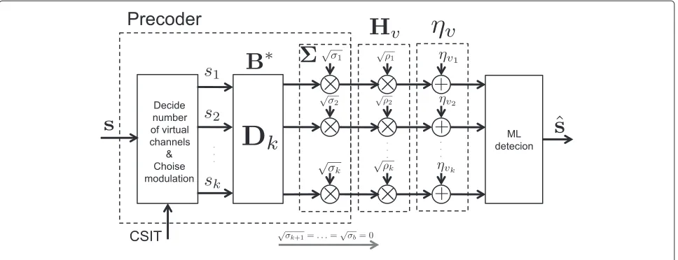
The precoding system structure, which contains an input-shaping matrix and a power allocation matrix, is shown in Figure 1. Due to different forms of CSIT, the precoder first decides number of virtual subchannels used for transmission, and then maps the data-bits intok sym-bols. The method used for selecting the modulation will be discussed in Section “Range of definition”. After that these symbols are pre-processed by a DFT block of sizek. At the end of the precoder, the transmit signal is directly
operated by a power distribution block, i.e., multiplied to a diagonal matrix.
The expression of the power allocation matrix depends on the symbol alphabet and the modulation used at the transmitter. In the following section, we propose a simple solution for one of the most common schemes: rectangular QAM.
Optimized precoder for rectangular QAM modulations
Expressions of the precoding matrix
For a rectangular 4m-QAM modulation, the transmit sym-bols belong to the set
S= √1 Ms{
a+b i;a−b i;−a+b i; −a−b i},
(28)
whereMs= 23(4m−1)anda,b∈ {1, 3,. . ., 2m−1}.
In the new precoding scheme, the input-shaping matrix
B∗ is given by a DFT-matrix of size b. Our objective becomes to determine the matrixsubject to the power constraint (12) in order to improve the minimum dis-tance performance. To derive the analytical solution of the power allocation matrixin (11), we have to follow three main steps:
(i) Eliminate the collinear difference vectorsx˘ ∈ ˘Xin order to reduce the space of solution.
(ii) For each transmit channel, implement a numerical research to determine which difference vectors providingdmin.
(iii) Equalize all difference distances of the vectors in step (ii) to obtain analytic solutions of the power
allocation matrix.
In the case of the 4m-QAM modulation, we have
(2m+1− 1)2b difference vectors. Some of them cannot provide the minimum distance. It is due to the collinear properties, for example,d2αx˘ = |α|2dx2˘ > d2x˘, with∀|α|>
1. For that reason, by eliminating all collinear difference vectors, we can reduce significantly the space of solutions. In step (ii), we first parameterize the power allocation matrix as the form of some trigonometric elements, such as,
=Esdiag(cosψ1, sinψ1cosψ2,. . .,
sinψ1sinψ2. . .sinψb) (29)
For each channelHv, a numerical search over all angles
ψi ∈ (0,π )in order to maximize the minimum distance
shows us which difference vectors providing the distance dmin. And finally, the analytic solution of the matrixcan
Figure 1Design model of the precoding matrix.
One should note that the set of difference vectors, which provide dmin, is not fixed. It changes according to the
channel values, and therefore lead to varies expressions of the matrix . For higher order QAM modulations, the form of our precoding matrix is more complicated. We propose, in this section, some characterized expres-sions of the new precoding scheme. These expresexpres-sions are only suitable for the small dispersive channels (i.e., there is no much difference of SNRs between each subchan-nel). However, we can use them for all transmit channels because of their large gain in the performance ofdmin.
The number of non-null diagonal elements in repre-sents the number of virtual-subchannels used for trans-mission. Let us denote the characterized expression of the precoder which enables powers on ksubchannels as Fk
withk=1,. . .,b. According to (25) and (27), the diagonal entries of the power allocation matrixcan be defined by
σi=
Es k
j=1φjρ−j 1
φiρi−1, (30)
where φj denotes the power coefficient of the jth vir-tual subchannel. It is obvious that the diagonal elements of are linearly proportional withφj. We note that the
value ofφjdepends on the set of the optimization vectors.
By equalizing the difference distances obtained by these vectors, we can derive the analytic values ofφj. Some
nor-malized coefficientsφjare described in Table 1. At the end
of this section, we show how to obtain this coefficient and propose a method for the general caseFk(Table 1).
Precoder F1
It is actually the max-SNR design which pours power on only the strongest virtual subchannel, i.e., = diag{√Es, 0,. . ., 0}. In order to retain the data-rate, the
precoderF1can use a higher-order QAM modulation. In
other words, it can transforms 4m-QAM signals onb vir-tual subchannels into a rectangular 4b.m-QAM signal on the first subchannel (detailed in Section “Range of defini-tion”). The minimum distance provided byF1is defined
by
d2F1 =
4 Ms
Esρ1. (31)
Precoder F2
This is the second expression of theN −dminprecoder
which is presented in our previous work [18]. We observe that the minimum distance is provided by two difference vectors x˘1 = √1M
s[ 0 2]
T, andx˘
2 = √1M
s[ 2 −2] T. By
substituting the DFT-matrix of sizebinto (11), we have
F2=
Es
2
cosψ 0 0 sinψ
1 1 −1 1
. (32)
The normalized distances provided by x˘1 and x˘2 are
given by ¯
dx2˘
1 =4ρ1cos
2ψ+4ρ 2sin2ψ
¯ dx2˘
2 =16ρ2sin 2ψ
Table 1 Optimized coefficients of the power allocation matrix
Expression φ1 φ2 φ3 φ4 φk
1 1
2 3 1
3 6+2√3 2+√3 1
4 9 5 1 1
By equalizingd¯2x˘ 1 = ¯d
2
˘
x2, we obtainψ=atan( √
ρ1/3ρ2).
The distancedminprovided byF2is
dF22 =
4 Ms
Es
2ρ1ρ2
ρ1+3ρ2 . (33)
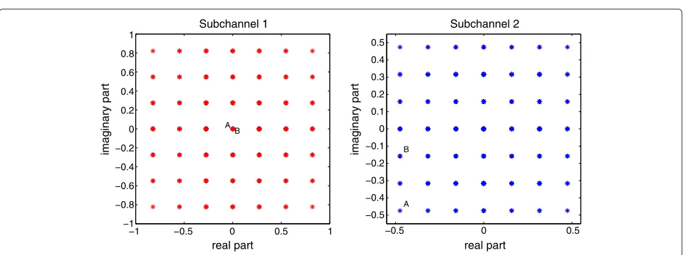
Figure 2 shows the received constellation provided by the precoderF2. It is observed that whenever two received vectors are close on one virtual subchannel, they are distant on the other (e.g., points A and B).
An exciting property of the precoding matrixF2is that the average number of neighbors providingdmin is less
than that of the optimized solution presented in [11]. For that reason, it provides a slight improvement in term of BER performance compared to the optimized max−dmin
precoder.
Precoder F3
This precoder pours power on three virtual subchannels, and has a characterized expression which is defined by
F3= √1
3 ⎛
⎝σ01 σ0 02 0
0 0 σ3 ⎞ ⎠
⎛ ⎜ ⎝
1 1 1
1 −1−
√
3i 2 −1+
√
3i 2
1 −1+
√
3i 2 −1−
√ 3i 2 ⎞ ⎟ ⎠. (34)
A numerical approach shows that the minimum dis-tance is provided by three difference vectors x˘1 =
1
√
Ms[ 0, 0, 2] T, x˘
2 = √1M
s[ 0, 2,−2]
T, and x˘
3 =
1
√
Ms[ 2,−2−2i, 2i]
T. One should note that three
differ-ence vectors do not always give the distancedmin. They
are only available for small dispersive channel, i.e.,ρ1is
not too higher thanρ2, andρ2is not much higher than ρ3. It is reasonable to choose these vectors, because when
the channel is large dispersive (ρ3 ρ2orρ2 ρ1, for
example), we can use the precoding matrixF2orF1.
By equalizing three difference distances provided by these vectors, we obtain
⎧ ⎪ ⎪ ⎪ ⎨ ⎪ ⎪ ⎪ ⎩
σ2/σ3=
2+√3
ρ2/ρ3
σ1/σ3=
6+2√3
ρ1/ρ3
(35)
The distancedminobtained byF3is then
dF23 = 4 Ms
Es
(3+√3)ρ1ρ2ρ3
ρ1ρ2+(2+
√
3)ρ1ρ3+(6+2
√ 3)ρ2ρ3
.
(36)
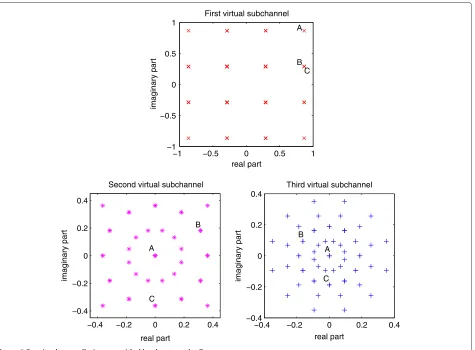
Figure 3 plots the received constellation provided by the precoderF3 in the case of 4-QAM. Like the case of the precoderF2, we observe that two received vectors
pro-cessed byF3are close on one virtual subchannel but can
be distant on the others (e.g., points B and C).
Precoder F4
The characterized expression of the precoding matrixF4
is given by
F4= 1
2 ⎛ ⎜ ⎜ ⎝
σ1 0 0 0
0 σ2 0 0
0 0 σ3 0
0 0 0 σ4 ⎞ ⎟ ⎟ ⎠ ⎛ ⎜ ⎜ ⎝
1 1 1 1 1 −i −1 i 1 −1 1 −1 1 i −1 −i
⎞ ⎟ ⎟
⎠. (37)
A numerical search shows that the minimum dis-tance is provided by x1˘ = √1
Ms[ 0, 0, 0, 2]
T, x2˘ =
1
√
Ms[ 0, 0, 2,−2] T, x˘
3 = √1M
s[ 0, 2,−2 − 2i, 2i] T, and
−1 −0.5 0 0.5 1
−1 −0.8 −0.6 −0.4 −0.2 0 0.2 0.4 0.6 0.8 1 A B real part imaginary part Subchannel 1
−0.5 0 0.5
−0.5 −0.4 −0.3 −0.2 −0.1 0 0.1 0.2 0.3 0.4 0.5 A B real part imaginary part Subchannel 2
−1 −0.5 0 0.5 1 −1
−0.5 0 0.5 1
First virtual subchannel
real part
imaginary part
C B A
−0.4 −0.2 0 0.2 0.4
−0.4 −0.2 0 0.2 0.4
Second virtual subchannel
real part
imaginary part
B
C A
−0.4 −0.2 0 0.2 0.4 −0.4
−0.2 0 0.2 0.4
Third virtual subchannel
real part
imaginary part
A B
C
Figure 3Received constellations provided by the precoderF3.
˘
x4= √1M
s[ 2,−2, 2,−2]
T. Like the case of the precoderF 3,
by equalizing their difference distances, we obtain
⎧ ⎪ ⎪ ⎪ ⎪ ⎪ ⎪ ⎨ ⎪ ⎪ ⎪ ⎪ ⎪ ⎪ ⎩
σ3/σ4=
1
ρ3/ρ4
σ2/σ4=
5
ρ2/ρ4
σ1/σ4=
9
ρ1/ρ4
(38)
The distancedminobtained byF4is given by
d2F4 =
4 Ms
Es
4
9/ρ1+5/ρ2+1/ρ3+1/ρ4. (39)
The general case Fk
In the case of k parallel datastreams, a first numerical approach is first consider to determine all optimization vectors. This numerical search is implemented for all anglesψi∈ (0,π )of the matrixin (29) to optimize the
distancedmin. Let us denotex1˘ ,x2˘ ,. . .,xk˘ askdifference
vectors providing the minimum distance. The distancedx˘i is given by
d2x˘i= ˘xi∗BϒB∗x˘i (40)
=
k
j=1
λj|ui(j)|2 (41)
whereϒ = ∗H∗vHv = diag(λ1,. . .,λk), and vectorui
is given by
ui=B∗x˘i=[ui(1),ui(2),. . .,ui(k)]T. (42)
By equalizing k difference distances, we have (k −1)
equations below
k
j=1 λj
|u1(j)|2− |ui(j)|2
=
k
j=1
λjvi,j=0, (43)
wherevi,j = |u1(j)|2− |ui(j)|2withi = 2,. . .,k. For a 4m
-QAM modulation, it is noted that the difference vector ˘
withj = 1. . .k. The power constrain in (12) can be now rewritten as
k
j=1 λj/ρj=
k
j=1
σj=Es. (44)
Let us defineλ=[λ1,. . .,λk]T, andv1,j =1/ρjwithj=
1,. . .,k, we have ⎛
⎜ ⎜ ⎜ ⎝
v1,1 v1,2 . . . v1,k
v2,1 v2,2 . . . v2,k
..
. ... ... vk,1 vk,2 . . . vk,k
⎞ ⎟ ⎟ ⎟ ⎠
⎛ ⎜ ⎜ ⎜ ⎝
λ1 λ2
.. .
λk ⎞ ⎟ ⎟ ⎟ ⎠=
⎛ ⎜ ⎜ ⎜ ⎝
Es
0 .. . 0
⎞ ⎟ ⎟ ⎟
⎠ (45)
or
Vλ=. (46)
In conclusion, the power coefficientsφiare proportional
to the entries of the vectorλwhich can be defined byλ=
V−1. The condition of the existence of the vectorλis that the matrixVis invertible. Whenx˘1=[ 0,. . ., 0, 2]T is one
of the difference vectors providing the minimum distance, the distancedminis then defined by
dF2k =4
k
j=1
λj. (47)
Range of definition
To improve the BER performance of a MIMO system, we choose from these precoding matrices above the precoder that provides the highest minimum Euclidean distance. One should note that the data-rate of a precoder Fi is
different to each other’s. For example, if we both use 4-QAM modulation for the precodersF1andF2, the bit-rate
ofF2 is twice as that ofF1. Therefore, we have to
con-sider the data-rate of the b precoders when comparing their distancesdmin. The error probability in (7) can be
re-expressed as
Pe≈NdminQ
¯ dmin
2 ×
SNRB fs
1 log2M
, (48)
where Mis the number of alternative modulation sym-bols,Bis the bandwidth, andfs is the symbol rate. For a
given modulation order, by comparing the right-hand side of (48) corresponding tob precoders, we can obtain the range of definition for each precoding scheme.
Another simple method to retain the data-rate is using different modulation for each precoder. Lets us come back to the example of the precodersF1andF2. If the 4-QAM
modulation is used for the precoder F2, it means that
two 2-bits symbols are transferred on two subchannels. Instead of transmitting like this, we can transfer one 4-bits symbols (16-QAM) on the first virtual subchannels. Then, two minimum distances that correspond toF1using 16-QAM andF2using 4-QAM are compared in order to
determine the range of definition for two precodersF1and
F2. ⎧ ⎪ ⎪ ⎨ ⎪ ⎪ ⎩
dF21 = 2 5Esρ1
dF22 =2Es
2ρ1ρ2 ρ1+3ρ2
(49)
In other words, ifd2F1 > dF22 or ρ1/ρ2 > 7: the
pre-coderF1is chosen, and forρ1/ρ2< 7: the precoderF2is
selected. Other precoders can be implemented in a similar way.
Simulation results
Comparison of minimum Euclidean distance
In this section, we indicate the improvement of the proposed precoder in terms of the minimum Euclidean distance compared to diagonal precoders. Indeed, the minimum Euclidean distance provided by a diagonal pre-coder is
dmin2 = min
s,r∈S,s=rHvFd(s−r) 2
= min
s,r∈S,s=r b
i
ρifi2|si−ri|2 (50)
where s =[s1,s2,. . .,sb]T, r =[r1,r2,. . .,rb]T, and Fd = diag(f1,. . .,fb). One should note that the
mini-mum Euclidean distance is obtained when the two vectors
sandrare different from only a symbol. The minimum Euclidean distance ofFdis then given by
dmin2 = min
s,r∈S,s=ri=min1...bρif 2
i |si−ri|2
= min
i=1...bρif 2
i s,rmin∈S,s=r|si−ri|2
= 4 Ms
min
i=1...bρif 2
i . (51)
It is noted that the diagonal entries of Hv =
diag(√ρ1,. . .,√ρb) are sorted in decreasing order, i.e., ρ1 ≥ ρ2 ≥ · · · ≥ ρb. By comparing all of elements
on right-hand side of (51), the minimum distances cor-responding to some traditional precoders such as beam-forming, max−λmin[8], Water-filling [4], and MMSE [7], can be determined. Table 2 illutrates the distance dmin
obtained by these diagonal precoders in comparison with our proposed precoder, in which(x)+def=max(x, 0).
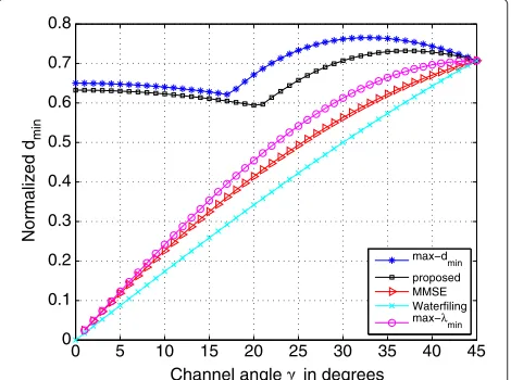
The normalized minimum distances provided by these precoder above, in the case ofb = 2 virtual subchannels and 4-QAM modulation, are illustrated in Figure 4. It is observed that our precoder provides a large improvement in terms ofdmincompared to the diagonal precoders. In
comparison with the max−dmin precoder presented in
Table 2 Comparison of the minimum Euclidean distances
Precoder Minimum Euclidean distanced2 min
Beamforming M4 sEsρ1 Water-filling M4
s
ρb Es+b
j=11/ρj
b −1
+
MMSE M4
s
√ρ
b Es+b
j=11/ρj
b j=11/√ρj −
1
+
max−λmin M4s Es
b j=11/ρj
Our proposed
⎧ ⎪ ⎪ ⎪ ⎪ ⎨ ⎪ ⎪ ⎪ ⎪ ⎩
4 Ms
Esρ1 forF1
4 Ms
Es 2ρ1ρ2
ρ1+3ρ2 forF2
. . . .
the max−dminprecoder [18]. According to that
improve-ment, an enhancement in terms of BER is expected for our new precoder (Table 2).
BER performance
In this section, the BER performance of the proposed pre-coder is considered in comparison with other traditional precoding strategies. The proposed precoder obtains a significant improvement of BER in comparison with the diagonal precoders: Water-filling, MMSE, and max−λmin. A gain about 6 dB can be observed at high SNR. Further-more, as discussed above, our precoder has the number of neighbors providing dmin less than that of the
opti-mal solution max−dmin in [11], although it has a small
difference in terms ofdmin. Therefore, the new precoder
provides a slight BER improvement compared to the max−dmin solution. The BER performance with respect
to SNR for two transmit datastreams and 4-QAM modu-lation is plotted in Figure 5.
0 5 10 15 20 25 30 35 40 45
0 0.1 0.2 0.3 0.4 0.5 0.6 0.7 0.8
Channel angle γ in degrees
Normalized d
min
max−d min proposed MMSE Waterfiling max−λmin
Figure 4Normalized minimum Euclidean distance for two datastreams and 4-QAM modulation, with the channel angle γ=atanρ2/ρ1.
The optimal solution for max−dmin precoder is
pre-sented in [11,12], but it is only available for two trans-mit datastreams with 4-QAM and 16-QAM modulations. By decomposing the channel into 2× 2 eigen-channel matrices and optimize the distancedminfor each pair of
datastreams, Vrigneau et al. [13] proposed a sub-optimal precoder for large MIMO channels. This extension is split into four steps: virtual diagonalization of the chan-nel, combination in pairs of sub-channels, application of the optimal 2D max−dminsolution, and power allocation
on each sub-system. However, this solution is also suit-able for low-order QAM modulations. A main advantage of our new precoder is that the solution is available for all rectangular QAM-modulations and for any number of datastreams.
For large MIMO simulations, we consider a system with nT = 5 transmit andnR = 4 receive antennas. The
bit-streams are separated into b = 4 independent virtual subchannels, and the channel matrixHis i.i.d. zero-mean complex Gaussian. For each SNR, the precoders are opti-mized for about 30,000 random matricesH. It is observed in Figure 5 that the BER performance of the max−λmin
solution is better than those of MMSE and Water-filling. Therefore, the max−λminprecoder is chosen to compare with our proposed precoder. Beside that some sophisti-cated transceivers such as: the Schur-convex ARITH-BER design [9], the linear precoder using Decision Feedback Equalization (DFE) [19], and the linear transceiver with bit allocation [20] are also mentioned in the comparison with our precoder. Figure 6 illustrates the BER performance for MIMO (5,4) systems using 4-QAM modulation. The com-parison of the proposed precoder and other schemes for b = 4 transmit datastreams shows that the performance is significantly enhanced in terms of BER. It is obvious that our precoder performs much better than diagonal
−2 0 2 4 6 8 10 12
10−6 10−5 10−4 10−3 10−2 10−1
SNR in dB
Uncoded BER
proposed max−d
min max−λmin
MMSE Waterfilling
−2 0 2 4 6 8 10 12 14 10−4
10−3 10−2 10−1
SNR in dB
Uncoded BER
MIMO−OFDM system (5,4) using 4−QAM, 128 subcarriers, Rayleigh fading channel
proposed E−d
min [12] DFE [18] ARITH−BER [9] max−λmin [8] MBitRate [19]
Figure 6Comparison of BER performance for large MIMO(5,4) systems.
precoders such as max−λminand Water-filling. Further-more, we observe that the new precoder also presents a significant improvement of BER compared to the DFE, the Schur-convex ARITH-BER, and the maximum bit-rate solutions, especially when the SNR is high. The new pre-coder was found to be better thanE−dminschemes and
this is due to the fact that not only the minimum distance, but also the number of neighbors providingdminis taken
into consideration.
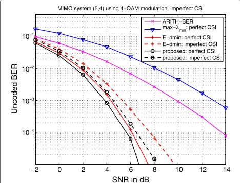
We also consider, in this section, the impact of imperfect CSI estimation on the BER performance of the proposed precoder. Figure 7 illustrates the BER performance with respect to SNR in the case of perfect CSI and imperfect CSI estimation. The estimated channel matrix of imper-fect CSI system can be modeled asHest=H+Herr, where
−2 0 2 4 6 8 10 12 14
10−4 10−3 10−2 10−1
SNR in dB
Uncoded BER
MIMO system (5,4) using 4−QAM modulation, imperfect CSI
ARITH−BER max−λmin: perfect CSI E−dmin: perfect CSI E−dmin: imperfect CSI proposed: perfect CSI proposed: imperfect CSI
Figure 7BER performance for perfect CSI and imperfect CSI estimations.
Herrrepresents the channel estimation error. The optimal training signals for the MIMO-OFDM channel estimation can be found in [21]. One should note that if the trans-mit channel is quasi-stationary, i.e., remains constant for several symbol periods, the precoding across time could be replaced by precoding across subcarriers [14]. In this simulation, we assume that the entries ofHerr are
com-plex Gaussian i.i.d random with mean zero and variance σerr=0.3σ, whereσis the variance of the complex Gaus-sian entries ofH. It is observed that the BER performance of our precoder decreases at high SNR, but it still remains better than the other precoding strategies. Furthermore, the BER enhancement obtained by the proposed precoder is much better than the case of full CSI in comparison with the E-dminsolution: a gain of 2 dB in SNR can be observed
at BER=10−5.
Conclusion
We proposed, in this article, a new linear precoder that is based on the maximization of the minimum Euclidean distance between two received data vectors. The sub-optimal design was obtained by observing the SNR-like matrix of the precoding matrix. An approximation of the minimum distance is derived, and its maximum value was obtained by maximizing the minimum diag-onal element of the SNR-like matrix. We then showed that the minimum diagonal element can be attained by a specific set of the precoder. Firstly, the precoding matrix is parameterized as the product of a diagonal power allocation matrix and an input-shaping matrix. The input-shaping matrix concerns with the rotation and scaling of the input symbols on each virtual sub-channel. We demonstrated that the minimum diagonal entry of the SNR-like matrix is obtained from a special choice of the input-shaping matrix, i.e., a DFT-matrix, and our objective becomes determining the power allo-cation matrix . As its name implies, the matrix decides how many subchannels are used by the pre-coder for data transmission. For each number of available datastreams, we proposed a simple characterized expres-sion of the precoding matrix for all rectangular QAM modulations.
We also presented some performance comparisons to demonstrate that the proposed precoder obtains a sig-nificant improvement in terms of BER. The improve-ment may be more than several dB at reasonable BER levels. In comparison with the optimal max−dmin
Competing interests
The authors declare that they have no competing interests.
Received: 1 August 2011 Accepted: 23 November 2012 Published: 2 March 2013
References
1. A Paulraj, D Gore, R Nabar, H Bolcskei, An overview of MIMO
communications-a key to gigabit wireless. Proc IEEE.92(2), 198–218 (2004) 2. G Foschini, Layered space-time architecture for wireless communication
in a fading environment when using multi-element antennas. Bell Labs. Tech J.1(2), 41–59 (1996)
3. M Vu, A Paulraj, MIMO wireless linear precoding. IEEE Signal Process Mag. 24(5), 86–105 (2007)
4. E Telatar, Capacity of multi-antenna Gaussian channels. Eur. Trans Telecommun.10(6), 585–595 (1999)
5. P Rostaing, O Berder, G Burel, L Collin, Minimum BER diagonal precoder for MIMO digital transmissions. IEEE Signal Process.82(10), 1477–1480 (2002) 6. P Stoica, G Ganesan, Maximum-SNR spatial-temporal formatting designs
for MIMO channels. IEEE Trans. Signal Process.50(12), 3036–3042 (2002) 7. H Sampath, P Stoica, A Paulraj, Generalized linear precoder and decoder design for MIMO channels using the weighted MMSE criterion. IEEE Trans Commun.49(12), 2198–2206 (2001)
8. A Scaglione, P Stoica, S Barbarossa, G Giannakis, H Sampath, Optimal designs for space-time linear precoders and decoders. IEEE Trans. Signal Process.50(5), 1051–1064 (2002)
9. D Palomar, J Cioffi, M Lagunas, Joint tx-rx beamforming design for multicarrier mimo channels: a unified framework for convex optimization. IEEE Trans. Signal Process.51(9), 2381–2401 (2003)
10. F Perez-Cruz, MRD Rodrigues, S Verdu, MIMO Gaussian channels with arbitrary inputs: optimal precoding and power allocation. IEEE Trans. Inf. Theory.56(3), 1070–1084 (2010)
11. L Collin, O Berder, P Rostaing, G Burel, Optimal minimum distance-based precoder for MIMO spatial multiplexing systems. IEEE Trans. Signal Process.52(3), 617–627 (2004)
12. Q-T Ngo, O Berder, B Vrigneau, O Sentieys, inIEEE International Conference on Communications (ICC). Minimum distance based precoder for mimo-ofdm systems using 16-qam modulation, (Dresden, Germany, June 2009)
13. B Vrigneau, J Letessier, P Rostaing, L Collin, G Burel, Extension of the MIMO precoder based on the minimum Euclidean distance: a cross-form matrix. IEEE J. Sel. Topics Signal Process.2(2), 135–146 (2008)
14. D Kapetanovi´c, F Rusek, inIEEE International Conference on
Communications (ICC). On precoder design under maximum-likelihood detection for quasi-stationary mimo channels, (Cape Town, South Africa, May 2010)
15. S Bergman, D Palomar, B Ottersten, Joint bit allocation and precoding for mimo systems with decision feedback detection. IEEE Trans. Signal Process.57(11), 4509–4521 (2009)
16. M Ma, X Huang, B Jiao, Y Guo, Optimal orthogonal precoding for power leakage suppression in dft-based systems. IEEE Trans. Commun.59(3), 844–853 (2011)
17. A Goldsmith,Wireless Communications. (Cambridge University Press, Cambridge, 2005)
18. Q-T Ngo, O Berder, P Scalart, inIEEE Wireless Communications and Networking Conference (WCNC). Reducing the number of neighbors in the received constellation of dmin precoded mimo systems, (Cancun, Mehico, March 2011)
19. M Shenouda, T Davidson, A framework for designing mimo systems with decision feedback equalization or tomlinson-harashima precoding. IEEE J. Sel. Areas Commun.26(2), 401–411 (2008)
20. C Li, Y Lin, S Tsai, P Vaidyanathan, Optimization of transceivers with bit allocation to maximize bit rate for mimo transmission. IEEE Trans Commun.57(12), 3556–3560 (2009)
21. H Minn, N Al-Dhahir, Optimal training signals for MIMO OFDM channel estimation. IEEE Trans. Wirel. Commun.5(5), 1158–1168 (2006)
doi:10.1186/1687-6180-2013-39
Cite this article as:Ngoet al.:General minimum Euclidean distance-based precoder for MIMO wireless systems.EURASIP Journal on Advances in Signal Processing20132013:39.
Submit your manuscript to a
journal and benefi t from:
7 Convenient online submission 7 Rigorous peer review
7 Immediate publication on acceptance 7 Open access: articles freely available online 7 High visibility within the fi eld
7 Retaining the copyright to your article