Novel Electrotextile Patch Antenna on Jeans Substrate
for Wearable Applications
Mohamed I. Ahmed1, *, Mai F. Ahmed2, and Abd-El A. Shaalan2
Abstract—This paper aimed to take closer steps towards real wearability by investigating the possibilities of designing and fabricating highly efficient and fully flexible wearable microstrip patch antenna for operating frequency of 5.8 GHz as a center frequency. Two types of conducting materials have been used for conducting parts: conventional metal plane and woven electro-textile material, while a non-conducting jeans fabric has been used as antenna substrate material. The dielectric constant εr= 1.78, and loss tangent tanδ= 0.085 of the jeans substrate measured by using two different methods. Also, the electromagnetic properties of the electro-textile are studied in details. The conductivity of e-textile cell is equal to 2.5×10⁶S/m and the surface impedance of e-textile cell equal to 0.0395 +J18.4 Ω. Furthermore, the proposed wearable antenna may be attached to human body, so the specific absorption ratio (SAR) must be calculated. Finally, the proposed design is simulated by CST simulator version 2016, fabricated using folded copper and measured by Agilent8719ES VNA.
1. INTRODUCTION
Wearable, body-worn antennas get more and more attention for body-centric communications because they can be easily worn on body and integrated into clothes [1]. Since 1997, wearable systems have become common subjects in researches. Many papers have been published about the design, fabrication and applications of these antennas. Some of these developments are reported in [2–4]. In recent years, electro-textiles (e-textiles) have taken a lot of attention as hopeful materials for the development of wearable antennas to make them fully flexible, which allows the smart clothes to communicate freely through wireless networks [5]. E-textiles are used as antenna patches and ground plane, while dielectric-textiles are used as antenna substrates [6–9].
In the antenna design, as the dielectric properties of the textile substrate, dielectric constant and loss tangent play important roles in the propagation of electromagnetic energy in dielectric media and have effect on the antenna performance [10]. The electromagnetic properties of the electro-textiles also play vital roles in antenna design and performance [11].
This paper includes an e-textile patch antenna design which is made from Jeans fabric substrate material with two types of conducting materials that will be discussed in more details in the following sections. Two different methods for fabric characterization are presented. The first method is a microstrip ring resonator. The second is DAC equipment (Dielectric Assessment Kit) setup to confirm the results. Further, this paper studies the electromagnetic properties of e-textiles for wearable antennas and calculates the basic resistance and inductance in a grid. Also, the SAR calculations for the presented antennas are performed on-body environments to ensure they operate properly in the nearness of the human body.
Received 3 March 2018, Accepted 12 April 2018, Scheduled 30 April 2018 * Corresponding author: Mohamed Ismail Ahmed ([email protected]).
2. MEASUREMENT OF JEANS TEXTILE CHARACTERISTICS
The dielectric constant and loss tangent for jeans textile material are measured by using two different methods. The first is a microstrip ring resonator method. The ring resonator model consists of a ring and two feed lines pasted on the upper surface of the jeans substrate. The ground plane occupies the lower surface of the jeans substrate, and a small gap Δ is also included between the ring and each feed line [12, 13]. The fabricated ring resonator model is shown in Fig. 1(a). By measuringS21for this model shown in Fig. 1(b), the dielectric constant and loss tangent for jeans textile material can be measured. The peak in S21 was recorded around each resonance. Thenth resonance occurs at [13]:
fn= nc
2πr√εr (1)
where r is the mean radius, c the speed of light in a vacuum, and εr the required relative dielectric
constant.
(a)
(b)
Figure 1. The fabricated ring resonator model pasted on jeans substrate: (a) fabricated geometry, and (b) measuredS21 with the frequency.
The insertion loss (S21 (dB)) is introduced as [13],
IL = 20 log10
1−QL Qu
(2) whereQL and Qu are the loaded and unloaded quality factors.
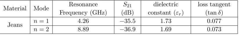
From the loaded and unloaded quality factors the loss tangent can be obtained and more details in [14]. The results of ring resonator method for characterization of jeans textile are mentioned in Table 1.
Table 1. The results of ring resonator method for characterization of jeans textile substrate.
Material Mode Resonance
Frequency (GHz)
S21 (dB)
dielectric constant (εr)
loss tangent (tanδ)
Jeans n= 1 4.26 −35.5 1.73 0.077
The second method is DAC (Dielectric Assessment Kit) equipment [15]. Therefore, it has been used to confirm the results determined using the first one. Comparing the obtained results using the two methods, it can be observed that close values are found between the two methods for jeans textile material and more details in [14]. The measured dielectric constant, loss tangent and thickness of the jeans substrate are mentioned in Table 2.
Table 2. The charactrization results of the jeans textile substrate.
Substrate Material Dielectric constant (εr) loss tangent (tanδ) Thickness (mm)
Jeans 1.78 0.085 0.6
Comparing the obtained results of the two methods, it can be observed that close values are found between the two methods for jeans textile material, but there are some slight differences between them, which is an inherent thing.
3. ELECTROMAGNETIC PROPERTIES OF E-TEXTILE CELL
Generally, there are two methods to make the dielectric textile electrically conductive. The first one is by applying conductive coating on the dielectric textile surface. The second is by interleaving normal fabrics with conductive metal threads via weaving or knitting [16]. However, woven fabrics perform better than coated fabrics, because of discontinuities of coated fabrics which increase the surface resistance [17]. We can also increase the conductivity of woven fabrics by increasing the conductive thread density in it.
Woven electro-textile fabric has more intersections in its pattern, which means that less distance between metal grids aligned along the current flow to keep conduction losses as low as possible as shown in Fig. 2 [18].
(a) (b)
Figure 2. Woven pattern of fabric: (a) front, (b) back [18].
In this paper, the e-textile has a woven pattern with woven density Nppi, and the conductive fabrics are made from round copper wires, with diameter of 80µm.
The distance between two conductive wires in any woven fabrics can be expressed as [18], d= 25.4−0.08N
N−1 (mm) (3)
If the distance between two conductive wires (d) is equal to 0.5 mm in this paper, the copper density in this fabric is 45 ppi.
Although connective threads are not normally considered components, they have very important properties of noise and high frequency performance of electronic circuits [19]. So, for the conductive threads whose length is a small fraction of the wavelength, the two most important characteristics are resistance and inductance [19]. In this paper, the proposed wearable antenna is used in the WiFi band, especially at 5.8 GHz. Furthermore, the wavelength can be calculated by:
wherec is the speed of light, andf is the resonance frequency.
While f0 = 5.8 GHz, the wavelength is equal to 51.7 mm. In addition, the electrical dimensions of the e-textile cells are electrical small approximately equal to λ/10, so we should construct lumped parameter electric circuit models. In many cases, the inductance is more important than resistance. Even at relatively low frequencies, a conductive thread usually has more inductive reactance than resistance [19].
3.1. Inductance of Round Conductive Threads
The total inductance is actually the sum of the internal inductance plus external inductance. The internal inductance is the effect of the magnetic field within the conductive wire itself, and it is usually negligible compared with the external inductance except for closely spaced conductive wires [19]. In addition, internal inductance is reduced even more when high-frequency currents are considered because as the result of skin effect, the current is concentrated near the surface of the conductor [19]. In this paper, the skin depth of the copper wires at resonance frequency can be calculated by [19],
δs= √ 1
πf0μ0σ
(5) wheref0is the resonance frequency,μ0 the permeability of free space,πa constant approximately equal to 3.14159, andσc the conductivity of copper wire (σc = 5.8×10⁷s/m).
While atf0 = 5.8 GHz, the skin depth is equal to 8.68×10⁻⁷, which is a little distance. Therefore, the external inductance is normally the only inductance of significance where the radius of the copper wire rc >2δs. In this paper, we assume that the two wires are separated (d/rc >5) (dis the distance
between the two wires). According to this condition, the per unit-length of the external inductance of two parallel wires can be expressed as [20],
l= μ0 π ln
d
rc (6)
whererc is the copper wire radius,μthe permeability of the free space (μ= 4π×10−7H/m), anddthe distance between two wires.
From Eq. (6), we can get that the per-unit-length inductance is 1.01×10⁻⁶H/m, and then the inductance in a grid length is L= 0.505 nH.
3.2. Resistance of Round Conductive Threads
Resistance is the second important characteristic of a round conductive copper wire. At high frequency, due to the skin effect, the resistance of conductive wires is a surface resistance where all the currents are surface currents [19]. In this paper, the ratio between the radius of the copper wire and skin depth isrc/δs ∼46. So, the per-unit-length of the surface resistance of copper wire can be expressed as [20];
r= 1
2rc
μ0f0
πσc rc δs (7)
where rc is the copper wire radius, μ the permeability of the free space (μ = 4π×10−7H/m), f the
operating frequency, σc the copper conductivity (σc = 5.8×10⁷S/m), anddthe distance between two
wire.
From Eq. (7), we can get that the per-unit-length resistance of copper wire is 79.06 Ω/m, and then the resistance in a grid length is R= 0.0395 Ω.
3.3. The Conductivity and Surface Impedance of E-Textile Cell
Now, we can calculate the conductivity of e-textile cell where the conductivity (σ) is the reciprocal of the resistivity (ρ). The resistivity of an e-textile cell can be calculated by [21],
ρ=r×A=r×πd 2
c
where r is the per-unit-length resistance of copper wire; A is the cross section area over which the current flows;dc is the diameter of the copper wire.
From Eq. (9), we can get that the resistivity is equal to 3.9×10⁻⁷Ω·m and then the conductivity of e-textile cell equal toσ = 1ρ= 2.5×10⁶S/m). Although electro-textile material has less conductivity than pure copper material (σ < σc), this material achieves real wearability for the body-worn microstrip
antenna Furthermore, the surface impedance of e-textile cell can be calculated by [21],
Z =R+J XL=R+J2πf0L (9)
whereRis the resistance in a grid length,πa constant approximately equal to 3.14159, f the operating frequency, andL the inductance in a grid length.
From Eq. (9), we can get the surface impedance asZ = 0.0395 +J18.4 Ω. Furthermore, the copper wire has very low resistance value, so the antenna with e-textile material is efficient and more flexible.
4. ANTENNA DESIGN
Three proposed microstrip patch wearable antennas operated at 5.8 GHz as a resonance frequency are designed and fabricated. Geometries of the three antennas are shown in Fig. 3. All geometry parameters of the presented antennas are the same and mentioned in Table 3.
(a) (b) (c)
Figure 3. The geometries of wearable antennas using different conductive part: (a) pure copper antenna; (b) semi-e-textile antenna, and (c) fully e-textile antenna.
Table 3. The dimensions of wearable patch antenna (unit: mm).
Width (W)
Length (L)
Width of Ground
(Wg)
Length of Ground
(Lg)
Width of inset feed
(Wf)
Length of inset feed
(Lf)
Length of Stub (Li)
Gap (g)
20 19.2 40 40 3 10 3 1.5
The antennas are pasted on jeans textile material as a substrate. The conductive part is different. The first one uses a pure copper tape for patch and ground plane. The second uses woven electro-textile material for patch and a pure copper tape for ground plane. The third uses woven electro-textile material for patch and ground plane to make a completely textile wearable antenna. Fabricated geometries of the three antennas are measured by Agilent8719ES VNA as shown in Fig. 4.
5. SIMULATED AND EXPERIMENTAL RESULTS
(a) (b) (c)
Figure 4. The fabricated antenna with connector and cable with Agilent8719ES VNA: (a) pure copper antenna; (b) semi-e-textile antenna, and (c) fully e-textile antenna.
Figure 5. The measured and simulatedS11 of the proposed pure copper antenna.
Fig. 7. From these results, it is found that the simulated results of the second simulation method agree well with the measured results compared to the first method and are more accurate. However, the first method of e-textile simulation provides better antenna performance than the second method.
From Fig. 6 and Fig. 7, in the first simulation method, both e-textile antenna resonances have gone down slightly to 5.85 GHz compared to the pure copper antenna resonance because the current flows along copper sheet with lower conductivity, and with decreasing the conductivity, the resonance frequency is also decreased. However, in the second simulation, the e-textile antenna resonances have gone up slightly to 5.85 GHz compared to the pure copper antenna resonance because of shorter current paths on the patch and the ground plane where the current flows in the copper threads only, and with decreasing the current flow path, the resonance frequency is increased. Further, by comparing the three curves it is found that the most suitable method to simulate the e-textile material is the second method which is more close to the fabrication.
Figure 6. The measured and simulatedS11 of the proposed semi-electro-textile antenna.
Figure 7. The measured and simulatedS11 of the proposed fully-electro-textile antenna.
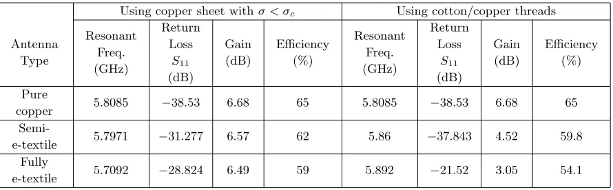
From Fig. 8 and Table 4, the pure copper tape antenna and semi-e-textile antenna have close values in the gain and efficiency and are better than the fully e-textile antenna. However, the copper tape is not reliable; it may be flaked off and breaks. Also, the e-textile antenna has some drawbacks. For example, there is an obvious offset in the frequency band as well as decreased radiation efficiency. So, the fully e-textile antenna is an efficient and fully flexible wearable microstrip patch antenna with acceptable performance.
Figure 8. The realized gains for the proposed antenna in different cases and by two simulation method.
(a) (b) (c)
Figure 9. The current distribution of different proposed antenna using copper sheet with σ < σc: (a) pure copper antenna; (b) semi-e-textile antenna, and (c) fully e-textile antenna.
Table 4. The simulation performance of the proposed patch antenna in the three cases.
Antenna Type
Using copper sheet withσ < σc Using cotton/copper threads
Resonant Freq. (GHz)
Return Loss
S11 (dB)
Gain (dB)
Efficiency (%)
Resonant Freq. (GHz)
Return Loss
S11 (dB)
Gain (dB)
Efficiency (%)
Pure
copper 5.8085 −38.53 6.68 65 5.8085 −38.53 6.68 65
Semi-e-textile 5.7971 −31.277 6.57 62 5.86 −37.843 4.52 59.8
Fully
e-textile 5.7092 −28.824 6.49 59 5.892 −21.52 3.05 54.1
(a) (b) (c)
Figure 10. The current distribution of different proposed antenna using cotton/copper threads: (a) pure copper antenna; (b) semi-e-textile antenna, and (c) fully e-textile antenna.
(a) (b)
Figure 11. Radiation pattern for the three antennas at 5.8 GHz in: (a) E-plane (ϕ = 0◦) and (b) H-plane (ϕ= 90◦) using copper sheet withσ < σc.
(a) (b)
(a) (b) (c)
Figure 13. SAR distribution on human voxel model (10 g) in distance 10 mm from antenna at 5.8 GHz: (a) pure copper antenna; (b) semi-e-textile antenna, and (c) fully e-textile antenna.
Table 5. The peak SAR values for the proposed antenna in three different cases in distance 10 mm from antenna at 5.8 GHz by FCC (1 g) & ICNIPR (10 g) standards.
Antenna Type SAR value (w/kg)
10 g 1 g
Pure copper 0.00339 0.00866 Semi-e-textile 0.00366 0.00933 Fully e-textile 0.00436 0.0111
6. CONCLUSION
This paper presents the design and fabrication of an efficient and fully flexible e-textile wearable microstrip patch antenna pasted on jeans textile material to operate at 5.8 GHz as a center frequency, aimed to achieve real wearability in the wearable antenna design. The dielectric propertiesεr = 1.78 of
the jeans substrate are measured by using two different methods: a microstrip ring resonator method and DAC (Dielectric Assessment Kit) equipment. The electromagnetic properties of e-textiles for wearable antennas like conductivity and surface impedance are studied. The basic resistance and inductance in a grid are calculated. Two methods are used for simulating the e-textile material in the simulation program. Although the first method obtains better performance results than the second, the second method is more close to the fabricated antenna. Further, the SAR value is considered an important parameter. In our design, the SAR value is very low and increased slightly by using e-textile material. All antennas are measured by Agilent 8719ES VNA. The measured results agree well with those obtained by the simulator from CST.
ACKNOWLEDGMENT
The authors acknowledge the Fabrics Department in National Research Center support generously research facilities.
REFERENCES
2. Langenhove, L. V., Smart Textiles for Medicine and Healthcare, CRC Press, Cambridge, England, 2007.
3. Park, S. and S. Jayaraman, “Wearable biomedical systems: Research to reality,”IEEE International Conference on Portable Information Devices, May 2007.
4. Sankaralingam, S. and B. Gupta, “Development of textile antennas for body wearable applications and investigations on their performance under bent conditions,” Progress In Electromagnetics Research B, Vol. 22, 53–71, 2010.
5. Kennedy, T. F., P. W. Fink, A. W. Chu, N. J. Champagne, G. Y. Lin, and M. A. Khayat, “Body-worn e-textile antennas: The good, the low mass, and the conformal,” IEEE Transactions on Antennas and Propagation, Vol. 57, 910–918, 2009.
6. Ouyang, Y., E. Karayianni, and W. J. Chappell, “Effect of fabric patterns on electro-textile patch antennas,” IEEE Antennas and Propagation Society International Symposium, Vol. 2B, 246–249, 2005.
7. Abbasi, M. A. B., S. S. Nikolaou, M. A. Antoniades, M. N. Stevanovi´c, and P. Vryonides, “Compact EBG-backed planar monopole for BAN wearable applications,” IEEE Transactions on Antennas and Propagation, Vol. 65, No. 2, 453–463, Feb. 2017.
8. Lotfi, P., S. Soltani, and R. D. Murch, “Printed endfire beam-steerable pixel antenna,” IEEE Transactions on Antennas and Propagation, Vol. 65, No. 8, 3913–3923, Aug. 2017.
9. Zhong, J., A. Kiourti, T. Sebastian, Y. Bayram, and J. L. Volakis, “Conformal load-bearing spiral antenna on conductive textile threads,”IEEE Antennas and Wireless Propagation Letters, Vol. 16, 230–233, 2017.
10. Kiourti, A., C. Lee, and J. L. Volakis, “Fabrication of textile antennas and circuits with 0.1 mm precision,”IEEE Antennas and Wireless Propagation Letters, Vol. 15, 151–153, 2015.
11. Ouyang, Y. and W. J. Chappell, “High frequency properties of electro-textiles for wearable antenna applications,” IEEE Transactions on Antennas and Propagation, Vol. 56, No. 2, Feb. 2008.
12. Hopkins, R. and C. Free, “Equivalent circuit for the microstrip ring resonator suitable for broadband materials characterization,”IET Microwaves, Antennas & Propagation, Vol. 2, No. 1 , 66–73, Feb. 2008.
13. Pozar, D. M., “Electromagnetic theory,” Microwave Engineering, 3rd Edition, John Wiley and Sons, Inc., Hoboken, NJ, 2005.
14. Ahmed, M. I., M. F. Ahmed, and A. A. Shaalan, “Investigation and comparison of 2.4 GHz wearable antennas on three textile substrates and its performance characteristics,”Open Journal of Antennas and Propagation, Vol. 5, 110–120, 2017.
15. https://www.speag.com/products/dak/dielectric-measurements/.
16. Quirk, M. M., T. L. Martin, and M. T. Jones, “Inclusion of fabric properties in the e-textile design process,” Proceedings of International Symposium on Wearable Computers, 37–40, 2009.
17. Locher, I., M. Klemm, T. Kirstein, and G. Tr¨oster, “Design and characterization of purely textile patch antennas,”IEEE Trans. Adv. Pack., Vol. 29, 777–788, 2006.
18. Ouyang, Y. and W. J. Chappell, “High frequency properties of electrotextiles for wearable antenna applications,” IEEE Transactions on Antennas and Propagation, Vol. 56, No. 2, 381–389, 2008. 19. Paul, C. R., Introduction to Electromagnetic Compatibility, 2nd Edition, Wiley, New York, 2006. 20. Quirk, M. M., T. L. Martin, and M. T. Jones, “Inclusion of fabric properties in the e-textile design
process,” Proceedings of International Symposium on Wearable Computers, 37–40, 2009. 21. Balanis, C. A.,Antenna Theory: Analysis and Design, 2nd Edition, Wiley, New York, 1996. 22. IEEE C95.1-2005, “IEEE standards for safety levels with respect to human exposure to radio
frequency electromagnetic fields, 3 kHz to 300 kHz,” Institute of Electrical and Electronics Engineers, New York, NY, 2005.
![Figure 2. Woven pattern of fabric: (a) front, (b) back [18].](https://thumb-us.123doks.com/thumbv2/123dok_us/1918501.1251730/3.612.145.471.411.528/figure-woven-pattern-fabric-b.webp)