Available online: https://edupediapublications.org/journals/index.php/IJR/ P a g e | 2578
Voltage Controlled DSTATCOM Using Fuzzy Controller for Power
Quality Improvement
1
S. R. Vairage,
2M.G. Poddar
1
Student, 2Assistant Professor
1, 2
Control Systems Engineering Dept.,
1, 2
MBES College of Engineering, Ambajogai, India
Abstract
The proposed schemes show voltage controlled distribution STATCOM compensator advantages over the traditional voltage
controlled DSTATCOM. The scheme generates a new algorithm for voltage controlled mode operation of distribution STATCOM
compensator to generate reference voltage. The proposed schemes ensure the unity power factor (1.0 p.u) to be achieved at the load
terminal during nominal operation which can’t be done in traditional method. The DSTATCOM injects lower current and reduces
loses in voltage source inverter and feeder, further the capacity of compensator to mitigate the voltage sag is increased. The
DSTATCOM can switch between current control mode (CCM) and voltage control mode (VCM) mode any time needed using fuzzy
which is not possible in the traditional method. The system also apt in tackling power quality problems by providing power factor
correction, voltage regulation and can free the system from harmonics by eliminating them and maintain load balance. The
experimental results along with simulations are demonstrated the system is efficient enough.
Key Words: current control mode, power quality (PQ), voltage-control mode, voltage-source inverter.
---***---1. INTRODUCTION
Distribution system plays a very important role between bulk
power source or sources and the consumer service switches
and is an inseparable part of electric system. A Distribution
system suffers from current as well as voltage-related
power-quality (PQ) problems via low power factor, distorted source
current, and voltage disturbances, harmonic distortion due to
harmonic current and also heating in the electrical equipments.
A DSTATCOM (STATCOM connected in the distribution
section hence DSTATCOM) connected at the point of
common coupling (PCC), has been utilized to mitigate both
types of PQ problems. The DSTATCOM can operate in VCM
and CCM mode but one at time the DSTATCOM when
operating in current control mode (CCM), it injects reactive
and harmonic components of load currents to make source
currents balanced, sinusoidal, and in phase with the PCC
voltages. In voltage control mode (VCM), the DSTATCOM
regulates PCC voltage at a reference value to protect critical
loads from voltage disturbances, such as sag, swell and
unbalances. However, the advantages of CCM and VCM
cannot be achieved simultaneously with one active filter
device, since two modes are independent of each other.
In CCM operation mode, the DSTATCOM cannot
of DSTATCOM is not useful under voltage disturbances,
which is major disadvantage of this mode of operation.
Traditionally, in VCM operation, the DSTATCOM regulates
the PCC voltage at 1.0 p.u. However, a load works
satisfactorily for a permissible voltage range. Hence it is not
necessary to regulate PCC voltage at 1.0 p.u. For maintain the
1.0.p.u voltages the DSTATCOM compensates for the voltage
drop in feeder. To compensate the voltage drop in feeder the
DSTATCOM has to provide additional reactive currents
which increase the source current which in turn increases the
losses in the voltage-source inverter (VSI) and feeder. Due
this increased current injection the VSI is de-rated in steady –
state condition. As a result of the above condition its
capability to mitigate deep voltage sag decreases. One more
hurdle is that UPF cannot be achieved when the PCC voltage
is 1 p.u. In the literature, so far, the operation of DTATCOM
is not reported where the advantages of both modes are
achieved depending on load requirements while overcoming
their demerits.
This paper considers the operation of DSTATCOM
in VCM and proposes a control algorithm to obtain the
reference load terminal voltage. This algorithm provides the
combined advantagesCCM andVCM. The UPF operation at
the PCC is achieved at nominal load, whereas fast voltage
regulation is provided during voltage disturbances. Also, the
reactive and harmonic component of load current is supplied
by the compensator at any time of operation. The discrete
PWM controller is used to generate switching pulses.
In this project, it uses a fuel cell, universal bridge of
three-level, neutral-point-clamped VSI is proposed which is
different from all other existing topologies. This structure
allows independent control to each leg of the VSI.
2. PROPOSED CONTROL SCHEME
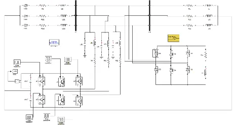
Circuit diagram of DSTSTCOM-compensated distribution
system shows the proposed fuel cell, universal bridge of
three-level, neutral-point-clamped VSI topology. This structure
allows independent control to each leg of the VSI [7]. Fig. 2
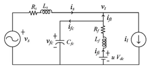
inductance and resistance are Lf and Rf respectively and the
shunt capacitor Cfc eliminates high-switching frequency
components.
Using discrete modeling of the system a discrete voltage
control law is obtained and it is also shown that the PCC
voltage can be regulated to the desired value with properly
chosen parameters of VSI. Then a procedure to design VSI
parameters is show cased. The DC capacitor voltage is
maintained at reference value using a proportional integral
(PI) controller [7].
Fig. 1 Diagram for D-STATCOM compensated distribution
system
Fig. 2 Single-phase equivalent circuit of DSTATCOM
The state-space equations for the circuit shown in fig are given
by
A =
[
0 C1fc 0
−1 𝐿𝑓
−𝑅𝑓
𝐿𝑓 0
−1
𝐿𝑠 0
−𝑅𝑠
𝐿𝑠]
B =
[
0 −C1fc 0
𝑉𝑑𝑐
𝐿𝑓 0 0
0 0 1
𝐿𝑠]
x =[ 𝑣𝑓𝑐 𝑖𝑓𝑖 𝑖𝑠]𝑡 z = [𝑢 𝑖𝑓𝑖 𝑣𝑠 ]𝑡
𝑣𝑓𝑐 (𝑘 + 1) = 𝐺11𝑣𝑓𝑐 (𝑘) + 𝐺12𝑖𝑓𝑖 (𝑘) + 𝐻11 𝑢(𝑘) +
𝐻12𝑖𝑓𝑡(𝑘) (2)
Where,
𝐺11 = 1 − 𝑇𝑑2 2𝐿 𝑓
⁄ 𝐶𝑓𝑐
𝐺12 = 𝑇𝑑⁄𝐶𝑓𝑐− 𝑇𝑑2𝑅𝑓⁄2𝐿𝑓𝐶𝑓𝑐
𝐺13 = 0
𝐻11 = 𝑇𝑑2𝑉
𝑑𝑐⁄2𝐿𝑓𝐶𝑓𝑐
𝐻12 = −𝑇𝑑⁄𝐶𝑓𝑐
𝐻13= 0
From (2) its seen that the terminal voltage can be maintained
at reference value depending upon the VSI parameters 𝑉𝑑𝑐,
𝐶𝑓𝑐, 𝐿𝑓, 𝑅𝑓 and the sampling time.VSI parameters must be
chosen carefully .let 𝑣𝑡∗ be the reference load terminal voltage.
A cost function J is chosen as follows [8]
J = [𝑣𝑓𝑐(𝑘 + 1)−𝑣𝑡∗(𝑘 + 1)]2 (3)
The dead beat control law form equation (2) can be given as
𝑢∗(𝑘) = 𝑣𝑡∗(𝑘+1)−𝐺11𝑣𝑓𝑐(𝑘)−𝐺12𝑖𝑓𝑖(𝑘)−𝐻12𝑖𝑓𝑡(𝑘)
𝐻11 (4)
Fig. 3 Overall control block diagram of the controller to
control DSTATCOM in distribution system
The future reference voltage which is unknown is predicted
one-step-ahead by using a second -order Lagrange
extrapolation formula as
𝑣𝑡∗(𝑘 + 1) = 3𝑣
𝑡∗(𝑘)−3𝑣𝑡∗(𝑘 − 1)+𝑣𝑡∗(𝑘 − 2) (5) 2.2 Design of VSI Parameters
DSTATCOM regulates terminal voltage satisfactorily,
depending upon the properly chosen VSI parameters. The
design procedure of these parameters is presented as follows.
2.2.1 Voltage Across DC Bus (𝐕𝐝𝐜): The dc bus voltage is
taken twice the peak of the phase voltage of the source for
satisfactory performance. Therefore, for a line voltage of 400
V, the dc bus voltage is maintained at 650 V.
2.2.2 DC Capacitance (Cdc): Values of dc capacitors are chosen based on a period of sag/swell and change in dc bus
voltage during transients.
𝐶𝑑𝑐= 2𝑝𝑆𝑇
𝑉𝑑𝑐𝑟𝑒𝑓2 − 𝑉𝑑𝑐2 (6)
Here, S=10 kVA, 𝑉𝑑𝑐𝑟𝑒𝑓=650 V, p=1, and 𝑉𝑑𝑐= 0.8
𝑉𝑑𝑐𝑟𝑒𝑓 or 1.2 𝑉𝑑𝑐𝑟𝑒𝑓. Using (6), capacitor values are found to
be 2630 uf and 2152 uf. The capacitor value 2600 uf is chosen
to achieve satisfactory performance during all operating
conditions.
2.2.3 Filter Inductance (Lf): Filter inductance (𝐿𝑓)should
provide reasonably high switching frequency and a sufficient
rate of change of current such that VSI currents follow desired
currents.
𝐿𝑓 = 2𝑉𝑚
(2ℎ𝑐)(2𝑓𝑚𝑎𝑥)=
0.5𝑉𝑚
ℎ𝑐𝑓𝑚𝑎𝑥 (7)
Where, 2ℎ𝑐 is the ripple in current. With 𝑓𝑚𝑎𝑥=10 kHz and
hc=0.75 A (5% of rated current), the value of 𝐿𝑓using (7) is
found to be 21.8 mH, and 22 mH is used in realizing the filter.
2.2.4 Shunt Capacitor(Cfc): The shunt capacitor should not
resonate with feeder inductance at the fundamental
frequency(𝜔𝑜). Capacitance, at which resonance will occur, is
𝐶𝑓𝑐𝑟 = 1
𝜔𝑜2𝐿𝑠 (8)
For proper operation, 𝐶𝑓𝑐 must be chosen very small
compared to 𝐶𝑓𝑐𝑟 (8) i.e 𝐶𝑓𝑐 <<𝐶𝑓𝑐𝑟 .
Here, a value of 5 uF is chosen which provides an Z=637ohm
at 𝜔𝑜.This does not allow the capacitor to draw significant
fundamental reactive current. In the traditional method, the
reference voltage is 1.0 p.u., whereas in the proposed
method, equation (9) is used to find the reference voltage.
(9)
3. INTRODUCTION TO FUZZY LOGIC
CONTROLLER
Fuzzy logic is originated as logic of ambiguous concepts.
Fuzzy set theory has been widely used in the area of industrial
controls; particularly in situations where conventional control
design techniques have been difficult to apply. The fuzzy
controller is used because of its advantages like it is very
robust, can be easily modified and cheaper to implement.
Simple fuzzy logic can be built up by group of rules based on
human knowledge of system behavior. A simulation model
can be built by using MATLAB/ simulink to study the
behavior and performance of the proposed controllers. Fuzzy
logic controller can also provide desirable control for both
small and large signal same time, which is not possible with
linear control technique. The fuzzy logic controller performs
its operation in four stages:
i. Fuzzification: it converts input data into suitable
linguistic values
ii. Knowledge base: it consists of a data base with
necessary linguistic definitions and the set of control
rules.
iii. Decision Making: this is a logic which simulates a
human decision process and infers the control action
using definitions of knowledge base
iv. Defuzzification : it is an interface which gives non
fuzzy control action from the output of decision
making logic [9]
Fig. 4 Proposed circuit with fuzzy controller
3.1. FUZZY LOGIC MEMBERSHIP FUNCTIONS
Membership function can have multiple different types, such
as triangular wave-form, trapezoidal, Guassian waveform,
bell-shaped waveform, sigmoidal waveform and S-curve
wave. The exact type depends on actual application. For those
systems that need significant dynamic variation in short period
of time, a triangular or trapezoidal waveform should be used.
For system that need very high control accuracy, Gaussian or
s-cure waveform should be selected.
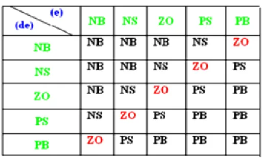
3.2 Rule Base Design
Fuzzy rules are conditional statement that specifies the
relationship among fuzzy variables. With the knowledge of
previous system behavior fuzzy rule are developed. The
objective of this paper is to control the output voltage of the
boost converter. The error and change of error of the output
voltage will be the inputs to the fuzzy logic controller. The
values of membership function are assigned to the linguistic
variables using five fuzzy subsets which are derived from
these 2 inputs as; “NB: Negative Big, NS: Negative Small, ZO: Zero Area, PS: Positive small and PB: Positive Big “[10].
Triangular membership functions are selected for all these
singletons. Rule base table formed based on human
controller, where all the entries of the matrix are fuzzy sets of
error (e), change in error (De) and output change in values.
These fuzzy control rules for error and change of error can be
referred in Table 1.
Table 1: Rule Base Design for Fuzzy Logic Controller
3.3 DEFUZZFICATION
The output of the inference mechanism is a fuzzy value, so it
is necessary to convert this fuzzy value into a real value, since
the physical process cannot deal with fuzzy value. This operation that is the inverse of fuzzification is known as defuzzification. The well-known center of gravity defuzzification method has been used because of its simplicity.
3.3 NORMALIZATION
Generally, the universes of discourse of input and output
variables of FLC are the real line. In practice, each universe is
restricted to an interval that is related to the maximal and
minimal possible values of the respective variable, that is, to
the operating range of the variable. The rules will not be
properly framed if the operating range is not suitably selected. For simplification and unification of the design of the FLC and
its computer implementation, however, it is more convenient
to operate with normalized universe of discourse of the
input/output variables of the FLC [10].
3.4 DENORMALIZATION
In denormalization process the output values of fuzzy
controller are converted to a value depending on the terminal
control element. In the denormalization procedure the
defuzzified normalized controller output uN is denormalized
with the help of an off-line predetermined scalar
denormalization Nu-1 which is the inverse of the normalization
factor Nu.
Let the normalization of the controller output be performed as:
uN= Nu.u (10)
Then, the denormalization of uN is simply:
u = Nu-1. uN (11)
The choice of the Nu essentially determines, together with the
rest of the scaling factors, the stability of the system to be
controlled.[11] Obtaining the normalization and
denormalization parameters of fuzzy controller is important
for system stability.
4. SIMULATION RESULTS
Fig. 5 Simulation circuit before compensation (Terminal
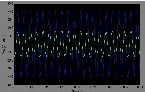
Fig. 6 Simulation wave form of terminal voltages and source
currents
Fig. 7 Simulation circuit for phase voltages, powers, source
and compensator rms currents
Fig. 8 The simulation wave form of terminal voltages and
source currents
a) Phase-a b) phase-b c) phase-c
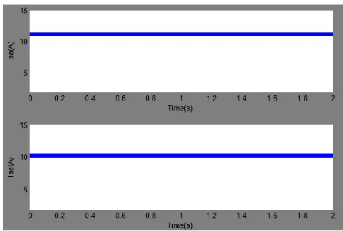
Fig. 9 Simulation wave form of phase-a compensator rms
currents (a) Old method (b) new method
Fig. 10 Simulation wave form of phase-a source rms currents
(a) Old method ( b) new method
Fig. 11 The simulation wave form of load(QL), compensator
(Qvsi) and PCC(Qpcc) reactive powers (a) Old method
Fig. 12 Simulation circuit for sag operation
Fig. 13 Simulation wave form of source voltage during sag
Fig. 14 Simulation wave form of terminal voltage after sag
Fig. 15 Simulation wave form of compensator rms current
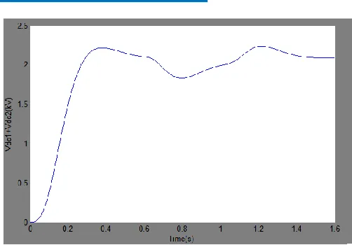
Fig. 16 The simulation wave form of voltage at DC bus
Fig. 17 Simulation wave form of source and terminal voltage
Fig.18 Simulation waveform for RES fed improved load angle
Fig. 19 Simulation wave form of RES fed improved load angle
Fig. 20 Simulation waveform of RES fed compensator rms
current
Fig. 21 Simulation wave form of RES fed DC voltage
Fig. 22 Simulation wave form of RES fed terminal voltage
Fig. 23 THD spectrums with fuzzy controller
5. CONCLUSION
The simulation results show that the proposed
scheme provides DSTATCOM, a capability to reduce several
PQ problems (related to voltage and current).In future, we can
use this type of topology to fulfill our requirements, as this
voltage, more terminal voltage compared to the existing
topology. The advantages of using the system are :
i) nearly UPF is maintained for a load change;
ii) fast voltage regulation has been achieved during
voltage disturbances; and
iii) losses in the VSI and feeder are reduced
considerably, and have higher sag
In future, we can use this type of topology to fulfill our
requirements, as this model gives more load current, more rms
current, more dc voltage, more terminal voltage compared to
the existing topology.
Since the renewable energy sources are available in
more quantity, they can replenish at any time and they are free
of cost in some situations. Even though if there are any
financial expenses if we spend one time the sources will last
long time when compared to non-renewable energy sources.
So, this project can serve any human being in future
to meet their continuous power supply without any
disturbances and they can lead a successful life.
6. REFERENCES
[1] C. Kumar and M. K. Mishra, "A Voltage-Controlled
DSTATCOM for Power-Quality Improvement," in IEEE
Transactions on Power Delivery, vol. 29, no. 3, pp.
1499-1507, June 2014.
[2] A. Jain, K. Joshi, A. Behal, and N. Mohan, “Voltage
regulation with STATCOMs: Modeling, control and results,” IEEE Trans. Power Del., vol. 21, no. 2, pp. 726–
735, Apr. 2006.
[3] M. K. Mishra and K. Karthikeyan, “A fast-acting dc-link
voltage controller for three-phase DSTATCOM to compensate ac and dc loads,” IEEE Trans. Power Del.,
vol. 24, no. 4, pp. 2291–2299, Oct. 2009.
[4] M. K. Mishra, A. Ghosh, A. Joshi, and H. M. Suryawanshi, “A novel method of load compensation under unbalanced and distorted voltages,” IEEE Trans. Power Del., vol. 22,
no. 1, pp. 288–295, Jan. 2007.
[5] M. K. Mishra, A. Ghosh, and A. Joshi, “Operation of a
DSTATCOM in voltage control mode,” IEEE Trans.
Power Del., vol. 18, no. 1, pp. 258–264, Jan. 2003. [6] A. Ghosh and G. Ledwich, “Load compensating
DSTATCOM in weak ac systems,” IEEE Trans. Power
Del., vol. 18, no. 4, pp. 1302–1309, Oct. 2003.
[7] A. Jain, K. Joshi, A. Behal, and N. Mohan, “Voltage
regulation with STATCOMs: Modeling, control and results,”IEEE Trans. Power Del., vol. 21, no. 2, pp. 726–
735, Apr. 2006.
[8] R. Gupta, A. Ghosh, and A. Joshi, “Switching
characterization of cascaded multilevel-inverter-controlled systems,”IEEE Trans. Ind. Electron., vol. 55, no. 3, pp.
1047–1058, Mar. 2008.
[9] P. Mitra and G. Venayagamoorthy, “An adaptive control
strategy for DSTATCOM applications in an electric ship power system,” IEEE Trans. Power Electron., vol. 25, no.
1, pp. 95–104, Jan. 2010.
[10] Chatterjee, Kalyan & Shankar, Ravi & K. Chatterjee, T.
(2015). “Load Frequency Control Considering Very
Short-term Load Prediction and Economic Load Dispatch Using
Neural Network and Its Application”, 327. Pp.75-89.
[11] Rainer Palm, Dimiter Driankov, Hans Hellendoorn, “Model Based Fuzzy Control: Fuzzy Gain Schedulers and
Sliding Mode Fuzzy Controllers”, Springer Science &