Marcelo AC Fernandes
Abstract
This work describes a new collaborative reception strategy designed to improve the performance and transmission capacity of the nodes of a wireless sensor network. The technique involves the use of a linear array of adaptive antennas, consisting of a set of sensors that operate in a collaborative manner as an adaptive spatial processor. It can be characterized as a single-input multiple-output (SIMO) system and exploits the spatial diversity of the sensors, which significantly improves performance in terms of energy consumption and transmission capacity. The principles of the proposed scheme are presented, together with bit error rate (BER) performance curves. The advantage of the technique is that it enables several sensors to transmit at very low powers, hence reducing energy consumption.
Keywords: Adaptive antennas; Collaborative reception; Wireless sensor
1 Introduction
The signals in wireless digital communication systems can be corrupted by various factors, especially thermal noise and multipath, resulting in frequency-selective fad-ing. The thermal noise, modeled using random variables with known probability distributions, can be effectively minimized using channel encoders that employ redun-dancy symbols to reconstruct the transmitted signal. Multipaths are mainly responsible for the appearance of intersymbol interference (ISI). This effect is characterized by the superimposition of symbols from a single source in the time domain. The ISI limits channel capacity and is one of the main problems in wireless communication sys-tems [1,2]. Various devices can be used in the reception process in order to minimize the effects of ISI, among which are spatial processors whose purpose is to eliminate undesired paths in order to recover the transmitted signal [3,4].
In a wireless sensor network (WSN), the sensors are highly limited in terms of processing ability, memory, and power, which hinders the use of sophisticated techniques in the reception process. However, a WSN permits the use of collaborative methods that are able to combine infor-mation among the network nodes. This work therefore
Correspondence: [email protected]
Department of Computer Engineering and Automation, Center of Technology, Federal University of Rio Grande do Norte (UFRN), Natal, Rio Grande do Norte, Brazil
proposes a collaborative reception technique that utilizes the spatial diversity of several sensors to produce an array of collaborative antennas that re-transmit the information (with diversity) to a single node that employs an adap-tive spatial processor. This proposal offers an alternaadap-tive for the deployment of an array of adaptive antennas with-out the need to construct devices with multiple antennas, hence improving transmission capacity and minimizing energy consumption.
The remainder of this work is organized as follows: Section 2 presents an overview of previous work related to collaborative transmission and reception techniques con-cerning the spatial diversity of nodes in sensor networks. Section 3 describes a mathematical model of a multipath communication channel. A brief description of adaptive antennas is given in Section 4. Section 5 presents the proposal for diverse collaborative transmission. Section 6 presents the energy consumption analysis. Simulation results are provided in Section 7, and Section 8 summa-rizes the main findings and suggests future directions.
2 Related work
A number of investigations have studied the use of spatial diversity as a means of improving transmission capacity in WSNs. The method described in [5] employed a receiver with a circular array of antennas to increase the gain of transmission from the nodes of a sensor network. Despite
not being collaborative, the scheme involved spatial diver-sity, and there were benefits in terms of gain. However, construction of the sensors required the use of four recep-tion antennas, which is a limitarecep-tion for a wireless sensor network whose devices have size limitations. An impor-tant point is that in transmission schemes with spatial diversity and adaptive antennas, the gain in capacity is proportional to the number of antennas [3].
The work described in [6-9] presented a collabora-tive space-time block coded (STBC) technique [10,11] in which the sensors formed a input and multiple-output virtual system (V-MIMO). The 2× 2 V-MIMO provided an energy saving of around 90% when compared with a conventional single-input and single-output (SISO) system. An interesting point of the work was that it con-sidered the correlation between the sensor data, which is a key aspect in development of V-MIMO systems. This paper considers flat-fading channel for long-haul com-munications and additive white Gaussian noise (AWGN) channel for local communications. A limitation was that the devices were assumed to havea prioriknowledge of the communication channel.
Also employing STBC, the work described in [12] presents a study of cooperative SBTC utilizing the low-energy adaptive clustering hierarchy protocol (LEACH). This protocol is widely used in WSN, and the paper com-pares the energy efficiency of cooperative SBTC with and without LEACH. A channel model with flat fading was used in all the simulations and results.
In [13], a collaborative transmission scheme was pre-sented that utilized the adaptive modulation technique in which each sensor (known as the user) transmitted its own information and re-transmitted that of the collaborators, using different modulation schemes. This could be char-acterized as a multiple-input and single-output (MISO) system and resulted in improved gain due to diversity [11]. The system assumed that the transmission channels were known and that they did not exhibit selective fading (assuming that all channels experience flat frequency and slow fading).
Collaborative transmission utilizing coded orthogonal frequency division multiplex (COFDM) [2] was presented in [14], where a source sensor transmitted its data to a group of repeater sensors that re-transmitted the signal collaboratively to another receptor sensor, forming a vir-tual COFDM system transmitting the same information in all the carriers. This system also exploited the spatial diversity of the sensors; however, it was assumed that the time delay for transmission between the re-transmitters and the receptor sensor was greater than the largest chan-nel delay. This condition implies the existence of large overhead (long guard time intervals) for extremely severe channel conditions. This study also assumes that all chan-nels are flat fading.
The work presented in [15], employing the same V-MIMO approach described in [6] and [9], studied tech-niques for channel encoding and its implications in V-MIMO systems. Frequency-flat Rayleigh fading chan-nels and perfectly synchronized (transmission/reception) wireless sensor nodes are assumed.
A proposal with arrays of adaptive antennas applied to WSN and operating in a collaborative manner can be found in [16]. This work discusses and analyzes the collaborative use of intelligent antennas, although no details are provided concerning the implementation or the operational results. Other papers presented in [17,18] introduce the concept of virtual antenna array in STBC system.
3 Characterization of the communication channel
The basic structure of a transmitter is shown in Figure 1, where a source of information generates complex sym-bols,a(n), belonging to an alphabet ofMpossible symbols (or modulation order). The symbols are transmitted dur-ing periods ofTs seconds, with each symbol being
rep-resented by words of b bits, where M = 2b. Ts is the
period of sampling of the symbols, or symbol interval. The complex signals,a(n), are expressed by
a(n)=aI(n)+jaQ(n), (1)
whereaI(n)andaQ(n) are the components of the phase and quadrature comprising the signal to be transmit-ted, respectively. The discrete symbolsa(n)are converted to analog by a digital-to-analog converter (DAC), and in some cases, when working with other frequency-multiplexed signals, the signal is shifted to a kth inter-mediate frequency, fk. After this step, the signala(t) is
processed by the radio frequency (RF) circuit, which in addition to other functions converts it to its operating fre-quency (also known as the carrier),fc. Finally, a signal is transmitted that can be expressed by
a(t)=Re{(aI(t)+jaQ(t))e(2π(fk+fc)t)}. (2)
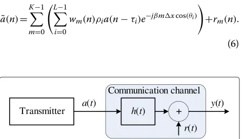
The symbolsa(t)are transmitted by means of a channel with impulse response,h(t), subject to multipath channel and AWGN,r(t), as illustrated in Figure 2. The sum of the channel output and the AWGN is expressed by
y(t)=ρ0a(t−τ0)+
L−1
i=1
ρia(t−τi)+r(t), (3)
4 Adaptive antennas
The antennas are usually arrayed in the form of a vec-tor of linearly equally spaced (LES) elements that direct the gain of the antenna in certain directions while nulling others. The maximum number of nulls is given byK−1, whereKis the number of elements in the array. The anal-ysis is simplified here by assuming that the space between the antenna elements isλ/2 and that there is no mutual coupling between them [3,4,19,20]. Figure 3 shows an LES array where the antenna elements are arranged along the x-axis, with spacing ofx. It is assumed that all the mul-tipaths arrive at the array in the horizontal plane, with angle of arrival (AOA) of θ radians in relation to they -axis orthogonal to thex-axis. Each mth element of the antenna array is weighted by a complex gainwm, and the
spacingxshould generally be greater than or equal to λ/2. The signaly(t)received by themth antenna element is given by
ym(t)=y(t)e−jβmxcos(θ)=y(t)v(θ), (4)
where β = (2π)/λ and v(θ) are known as the signa-ture of the signal on themth antenna element. Rewrit-ing Equation 4 and substitutRewrit-ingy(t)by its expression in Equation 3 gives
ym(t)= L−1
i=0
ρia(t−τi)e−j(mβ)xcos(θi)+rm(t), (5)
where rm(t) is the noise associated with each antenna
element. The combined output of the signals of the K elements,a(n), is represented by
˜ a(n)=
K−1
m=0 L−1
i=0
wm(n)ρia(n−τi)e−jβmxcos(θi)
+rm(n).
(6)
Figure 2Model of a communication channel with ISI and AWGN.
It can be seen from Equation 6 that eachith path is weighted by its AOA,θi, and by its position in the spatial
vector. This enables the spatial processor to distinguish and eliminate undesirable paths. Various algorithms exist that can be used to automatically adjust the weightings, wm, and here, the technique governed by the least mean
squares (LMS) algorithm [21,22] was employed.
5 Collaborative linear array
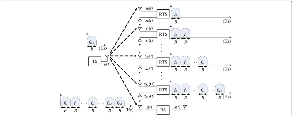
Figure 4 shows the structure of the WSN with spatial diversity, in which K sensors linearly arranged in space can operate collaboratively as a linear array of antennas, as described in Section 4. There are three types of sensors in this scheme: the transmission sensor (TS) node, the re-transmission sensor (RTS) node, and the receiving sensor (RS) node.
Figure 4Collaborative structure of sensors functioning as a linear array of antennas.
The TS node generates the data source to be trans-mitted, the RTS node functions as an antenna element within the collaborative array and re-transmits the infor-mation received using a different carrier, and the RS node acts as the final antenna of the array of K ele-ments and also impleele-ments the adaptive spatial pro-cessor to combine the signals received from the RTS nodes.
In the proposed method, the communication channels between the TS node and the RTS and RS nodes can be treated as having frequency-selective fading (due to the multipath). The communication between the RTS node and the RTS and RS nodes, is considered: AWGN chan-nel with space propagation loss [6,9,14]. Meanwhile, it is important to note that in the case of the RTS, the minimum distance isλ/2, as described in Section 4.
Frequency-division multiplexing (FDM) between all the signals was utilized in order to minimize the interference between the signals of the collaborative array and at the same time simplify implementation of the RTS nodes. FDM [1,2] ensures orthogonal channels between the sig-nals, and its simplicity avoids the need for more complex circuits and elaborate schemes for frame synchronization between the RTS devices.
In the TS node (shown in Figure 1), the transmission signala(t)shifted to an intermediate frequencyfK−1can
be expressed by
a(t,fK−1)=Re{(aI(t)+jaQ(t))e(2π(fK−1+fc)t)}. (7)
This signal is then transmitted through channel h(t), together with AWGN, and is subsequently received by the
K−1 RTS and RS nodes by means of the signaly(t,fK−1). Re-writing Equation 3, the signaly(t,fK−1) can be char-acterized in terms of the intermediate frequency, fK−1, resulting in the following expression:
y(t,fK−1)= L−1
i=0
ρia(t−τi,fK−1)+r(t,fK−1). (8)
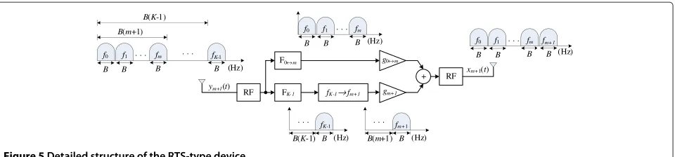
Each mth RTS, shown in Figure 5, receives the signal ym(t), which is characterized as
ym(t)=
y(t,fK−1)v(θ) m=0 xm−1(t,f0→m−1)+y(t,fK−1)v(θ)m=0
,
(9)
wherev(θ)is the signature of the spatial position of the sensor, as shown in Equation 4, andxm−1(t,f0→m−1)is the
signal transmitted by the previous RTS sensor.
The RTS processes the signalym(t)through an RF
cir-cuit, removing the carrier, fc, and shifting the signal to its baseband. After this step, the signalym(t)is separated
into two parts by the filters F0→m andFK−1. These are
a low-pass filter with cut frequency of m×B (Hz) and a band-pass filter at frequencyfK −1, respectively. After
passing through filter FK−1, the signalyK−1is shifted to frequencyfm, generating the signalym(t)that is then
mul-tiplexed with the signal exiting filterF0→m, producing the
signalxm(t), expressed as
xm(t,f0→m)= m−1
m=0
Figure 5Detailed structure of the RTS-type device.
Finally, the RS node, illustrated in Figure 6, receives the signalz(t), composed of all the frequency-multiplexed signals and expressed as
z(t) = xK−2(t,f0→K−2)+y(t,fK−1)v(θ)+r(t,fK−1)
=
K−1
m=0
y(t,fm)v(θ)+r(t,fm) (11)
which can be re-written, substituting Equations 3 and 4, and expressed by
z(t)= K−1
m=0
L−1
i=0
ρia(t−τi,fm)e−j(mβ)xcos(θi)
+rm(t,fm).
(12)
The received signal,z(t), is then filtered through a set of K band-pass filters, F0. . .Fm. . .FK−1, and then
dis-cretized, generating the signalu(n)mdescribed by
um(n)= L−1
i=0
ρia(n−τi,fm)e−j(mβ)xcos(θi)+rm(n,fm).
(13)
The output is combined by the spatial processor, result-ing in the signala˜(n), which is similar to that shown in Equation 6.
Adaptation of the gain employs two training modes, supervised and unsupervised. In the supervised mode, the error signal is given by
e(n)=atr(n)− ˜a(n), (14)
whereatr(n)is the training sequence known beforehand. In the unsupervised mode, the decision-directed (DD) algorithm [2,21] is used, and the error signal is given by
e(n)= ˆa(n)− ˜a(n), (15)
whereaˆ(n)is the estimate of the decision on the received signal.
6 Energy consumption computation
The total energy consumed per bit,EbCLA, in the collabo-rative linear array (CLA) can be expressed as
EbCLA=ETSb +(K−1)EbRTS+EbRS
= PTS
Reff +(
K−1)P RTS
Reff + PRS Reff ,
(16)
whereETSb ,EbRTS, andERSb are the energies consumed per bit associated with node sensors of the types TS, RTS, and RS, respectively. The variablesPTSb ,PRTSb , andPRSb are the powers of each type of node sensor, andReffis the effective transmission rate characterized as
Reff=
100−Ntr
100 Rb, (17)
whereNtris the percentage of symbols in a frame used for training, andRbis the total transmission rate in bits per second (bps), expressed asRb=b/Ts.
Based on the works presented in [7-9,23,24], the power required for TS node transmission can be expressed as
PTS=PTSPA+PCBTS, (18)
where PTSPA and PTSCB are the power consumed by the power amplifier and by other circuit blocks associated with the TS node, respectively. The first term,PPATS, can be expressed as
the drain efficiency of the RF power amplifier,ηTSis the peak-to-average ratio (PAR), and
PTSout= (4π)
where dTS is the distance between the TS node and the RTS and RS nodes, κ is an integer between 2 and 4 (κ = 2 corresponding to free space propagation),GTStx is the transmitter antenna gain,GTS
rx is the receiver antenna gain, MlTS is the link margin compensating the hard-ware process variations and other additive background noise or interference, andNfTSis the receiver noise figure, defined asNfTS=NrTS/N0TS, whereN0TSis the single-sided thermal noise power spectral density (PSD) at room
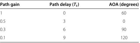
tem-Table 1 Angles of arrival for each path of the channel described in Equation 30
Path gain Path delay (Ts) AOA (degrees)
1 0 60
0.5 3 0
0.3 6 90
0.1 9 120
perature,NrTSis the PSD of the total effective noise at the receiver input, andE¯bTSis the required energy per bit at the receiver for a given BER requirement [7,23,24]. The second term,PTSCB, can be expressed as
PTSCB=PTSDAC+PmixTS +PfiltTS+PTSsyn, (21)
wherePDACTS ,PmixTS,PTSfilt andPTSsynare the power consump-tion values for the D/A converter (DAC), the mixer, the active filters (transmission), and the frequency synthesizer associated with the TS node, respectively.
Following the same reasoning as for the TS node, the power consumption of each mth RTS node can be expressed as
Table 2 Simulation parameters
Parameter Value
PDAC 15.4368 mW
PLNA 20 mW
PIFA 3 mW
PADC 6.6978 mW
σ2=N0
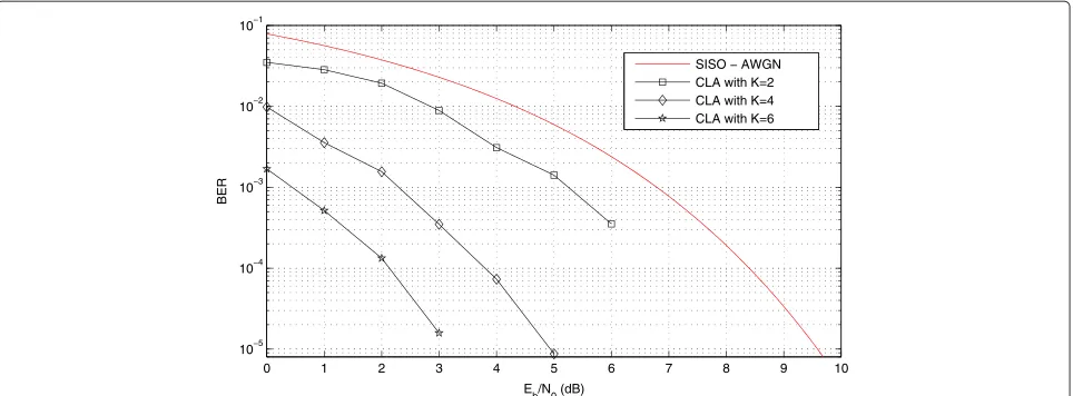
Figure 7The BER results for the 4-QAM with 2, 4, and 6 nodes (antennas).Performance curve of BER as a function ofEb/N0for a collaborative array with 2, 4, and 6 nodes, functioning with a 4-QAM system in an AWGN channel.
and
PRTSCB =2PRTSfilr +2PRTSLNA+PRTSsyn +PmixRTS+2PRTSfilt . (25)
In the above expressions,PfilrRS andPLNARTS are the power consumption of the active filters (reception) and the low-noise amplifier (LNA), respectively. Finally, the power consumed by the RS node is given by
PRS=PRSCB=K PRSfilr+PRSLNA+PmixRS +PRSIFA+PRSADC
+PRSsyn,
(26)
wherePRSIFAandPRSADCare the power consumption values for the intermedia frequency amplifier (IFA) and the A/D converter (ADC) associated with the RS node,
respec-tively. The theoretical values ofE¯bTSandE¯RTSb for AWGN channels among all the sensor nodes can be expressed by
¯
ETSb = ¯ERTSb = (M−1)N0 3bK
⎡ ⎣Q−1
⎛
⎝ P¯bTSb 4 1− √1
M
⎞ ⎠ ⎤ ⎦ 2
.
(27)
This information is important because it establishes the lower bound of the CLA.
In the case of the SISO system, the power consumed can be described by
ESISOb = P
TS+PRS
Rb
forK=1 (28)
0 2 4 6 8 10 12 14
10−5 10−4 10−3 10−2 10−1
Eb/N0 (dB)
BER
SISO − AWGN CLA with K=4 CLA with K=6 CLA with K=8
0 2 4 6 8 10 12 14 16 18 10−5
10−4 10−3 10−2 10−1
E b/N0 (dB)
BER
SISO − AWGN CLA with K=6 CLA with K=8 CLA with K=10
Figure 9The BER results for the 64-QAM with 6, 8, and 10 nodes (antennas).Performance curve of BER as a function ofEb/N0for a collaborative array with 6, 8, and 10 nodes, functioning with a 64-QAM system in an AWGN channel.
and for SISO QAM systems (with b even and Gray bit mapping), the values ofE¯TSrmb in AWGN channels can be expressed as
¯
ETSb = (M−1)N0 3b
⎡ ⎣Q−1
⎛
⎝ P¯TSb b 4 1−√1
M
⎞ ⎠ ⎤ ⎦ 2
, (29)
whereP¯brepresents the average BER value.
7 Simulation results
Validation of the CLA, and evaluation of its performance and reliability in a wireless sensor network, was achieved by conducting simulations for 4-QAM, 16-QAM, and 64-QAM digital communication systems, without channel encoding, at a rate of Rb = 10 kbps with a carrier fre-quencyfc=2.5 GHz. Curves were then plotted of BER as a function ofEb/N0, which denotes the relation between bit energy and the spectral power density of the noise, as
0 50 100 150 200 250 300 350
0 50 100 150 200 250
Distance in meters (dTS) between node TS and nodes RTS and RS.
Total energy consumption per bit in uJ (micro Joules)
SISO − AWGN
CLA with K=2 and Ntr=10%
CLA with K=2 and N
tr=20%
CLA with K=4 and N
tr=10%
CLA with K=4 and Ntr=20%
CLA with K=6 and N
tr=10%
CLA with K=6 and N
tr=20%
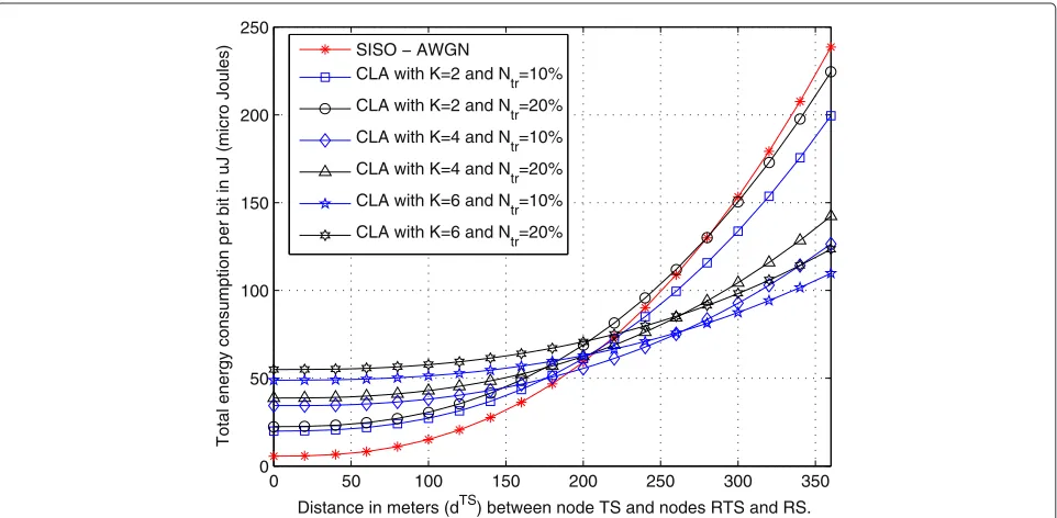
Figure 11Comparison of the energy consumption for the CLA and SISO.16-QAM modulation and AWGN in all communication links.
well as curves of the radiation pattern of the collabora-tive array. Also presented is a comparison of the energy consumption curves for the CLA and a SISO system. The evaluation considered two scenarios. The first was char-acterized by the use of AWGN channels between all the nodes: from TS to the RTS and RS nodes, between the RTS nodes, and between the K−1th RTS node and the RS node. The second scenario used a multipath chan-nel between the TS node and all the RTS nodes and the RS node, and in the remainder, an AWGN channel was
employed, as in the first scenario. The multipath channel was modeled using the expression
h(t)=δ(t)+0.5δ(t−3Ts)+0.3δ(t−6Ts)+0.1δ(t−9Ts),
(30)
where the angle of arrival for each path was as shown in Table 1. All the other parameters used in the simulations are presented in Table 2 [7-9,23,24].
0 20 40 60 80 100 120 140 160
0 50 100 150 200 250 300 350
Distance in meters (dTS) between node TS and nodes RTS and RS.
Total energy consumption per bit in uJ (micro Joules)
SISO − AWGN
CLA with K=6 and Ntr=10%
CLA with K=6 and N
tr=20%
CLA with K=8 and Ntr=10%
CLA with K=8 and Ntr=20%
CLA with K=10 and N
tr=10%
CLA with K=10 and Ntr=20%
0 100 200 300 400 500 600 0
10 20 30 40 50 60 70 80 90 100
Distance in meters (dTS) between node TS and nodes RTS and RS.
Energy efficiency (%)
CLA with K=2 and N
tr=10%
CLA with K=2 and N
tr=20%
CLA with K=4 and Ntr=10%
CLA with K=4 and N
tr=20%
CLA with K=6 and N
tr=10%
CLA with K=6 and Ntr=20%
Figure 13Energy saving for the CLA as a function ofdTS.4-QAM modulation and AWGN in all communication links.
7.1 First scenario: AWGN channel
The results of the simulations for the AWGN channel (Figures 7, 8, and 9) demonstrate the diversity gains pro-vided by the proposed system, as well as the lower limits associated with each of the simulated communication systems. In this scenario, all the curves were obtained by simulation as well as by using Equation 29 for SISO AWGN.
Figure 7 shows the results for the 4-QAM system with 2, 4, and 6 sensors in the collaborative array, together with the theoretical curve for a conventional system with one antenna (SISO). From the BER curve, it can be seen that there was an increase in gain of approximately 2.5 dB for each addition of two nodes in the collaborative array, arriving at approximately 7.5 dB with six nodes. Figure 8 shows the results for the 16-QAM system using 4, 6, and 8
0 50 100 150 200 250 300 350 400
0 10 20 30 40 50 60 70 80 90 100
Distance in meters (dTS) between node TS and nodes RTS and RS.
Energy efficiency (%)
CLA with K=4 and N
tr=10%
CLA with K=4 and N
tr=20%
CLA with K=6 and Ntr=10%
CLA with K=6 and N
tr=20%
CLA with K=8 and Ntr=10%
CLA with K=8 and Ntr=20%
Figure 15Energy saving for the CLA as a function ofdTS.64-QAM modulation and AWGN in all communication links.
nodes, where there was also an increase in gain of around 2.5 dB, relative to the conventional system, for each addi-tion of two sensors. Finally, Figure 9 shows the results for 6, 8, and 10 nodes associated with a 64-QAM system, with increases in gain of about 1 dB between the experiments. It is important to point out that depending on the density of sensors, a substantially greater quantity of nodes with antennas could be used, hence improving the capacity of the system by several decibels. Another point to be noted is that energy consumption by the receiver and transmitter could be considerably reduced by working at low values of Eb/N0.
Figures 10, 11, and 12 show the energy consumed by the CLA, compared to the SISO system, as a function of the distance between the TS node and the RTS and RS nodes (dTS), for the 4-QAM, 16-QAM, and 64-QAM systems, respectively. Figures 13, 14, and 15 show the energy saving achieved by the CLA, compared to the SISO system (defined as ESISOESISO−ECLA) [8,9]. These simulations
considered curves for different quantities of nodes in the collaborative array (K > 1), with two training sequence length situations (Ntr = 10% and20%). The consumption curves were obtained using the value ofEbfor a BER of 10−3(in other words,Pb=10−3).
0 2 4 6 8 10 12 14 10−6
10−5 10−4 10−3 10−2 10−1
E b/N0 (dB)
BER
SISO − AWGN SISO − Multipath channel CLA with K=4
CLA with K=6 CLA with K=8
Figure 17The BER results for the 16-QAM with 4, 6, and 8 nodes (antennas).Performance curve of BER as a function ofEb/N0for a collaborative array with 4, 6, and 8 nodes (antennas), functioning with a 16-QAM system in a multipath channel (see Equation 30) and AWGN.
For all the QAM systems simulated (M=4, 16 and 64), it could be observed (see Figures 10, 11, and 12) that for K>1, there was a distancedwhere the energy consump-tion of the CLA was smaller than that of the SISO system, even using an overhead ofNtr = 20%. Another interest-ing feature was that the greater the number of RTS nodes (orKvalue), the smaller was the consumption of the CLA, relative to the SISO. On the other hand, the distance at which the consumption was smallest increased. It was also found that the greater the level of modulation, the smaller was the distance at which the CLA consumed less energy,
relative to the SISO. These features can also be seen in the energy saving curves (see Figures 13, 14, and 15), where the energy saving gain is proportional to the number of RTS nodes (orK).
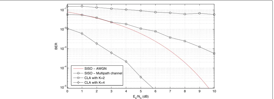
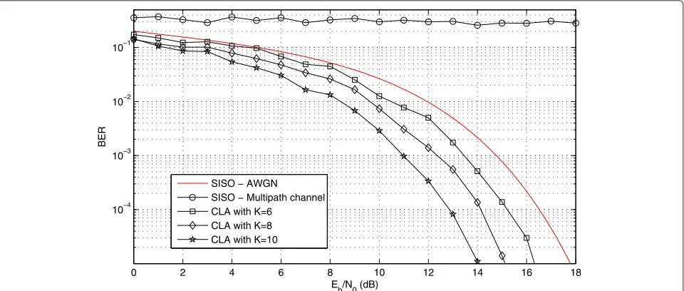
7.2 Second scenario: multipath and AWGN channel The Eb/N0 curves for the 4-QAM, 16-QAM, and 64-QAM system simulations employing the second scenario with the channel h(t) (see Equation 30) and AWGN are presented in Figures 16, 17, and 18, respectively. The curves obtained for the collaborative array radiation
0 2 4 6 8 10 12 14 16 18
10−4 10−3 10−2 10−1
Eb/N0 (dB)
BER
SISO − AWGN SISO − Multipath channel CLA with K=6
CLA with K=8 CLA with K=10
0 50 100 150 200 250 300 350 0
50 100 150
Distance in meters (dTS) between node TS and nodes RTS and RS.
Total energy consumption per bit in uJ (micro Joules)
Figure 19Comparison of the energy consumption for the CLA and SISO.4-QAM modulation, multipath channel (see Equation 30) between the TS node and all the RTS nodes and the RS node, and in the remainder, AWGN channel.
pattern are also shown for different numbers of nodes. For systems with one antenna, the performance limit for multipath channel is the BER curve for AWGN channels [1,2]. Hence, it can be observed in Figures 16, 17, and 18 that depending on the number of nodes (antennas), the performance of the collaborative array was superior to the limiting condition for systems with one antenna,
as expected for comparison between a SISO system and a MISO system [11].
In the case of the 4-QAM system (Figure 16), in which 4 or more collaborative nodes were employed, the perfor-mance of the system was higher relative to the theoretical SISO curve. This behavior was repeated for the other sys-tems, with four nodes required for the 16-QAM system,
0 20 40 60 80 100 120 140 160 0
50 100 150 200 250 300 350
Distance in meters (dTS) between node TS and nodes RTS and RS.
Total energy consumption per bit in uJ (micro Joules)
SISO − AWGN
CLA with K=6 and Ntr=10%
CLA with K=6 and Ntr=20%
CLA with K=8 and N
tr=10%
CLA with K=8 and Ntr=20%
CLA with K=10 and N
tr=10%
CLA with K=10 and N
tr=20%
Figure 21Comparison of the energy consumption for the CLA and SISO.64-QAM modulation, multipath channel (see Equation 30) between the TS node and all the RTS nodes and the RS node, and in the remainder, AWGN channel.
and six nodes required for the 64-QAM system, although the findings cannot be generalized due to the dependence on the h(t) channel. On the other hand, it can be con-cluded that the greater the quantity of collaborative nodes, the better the performance relative to the conventional system.
Similar to the simulations for the AWGN channel, Figures 19, 20, and 21 show the energy consumed by the
CLA, compared to the SISO system, as a function of the distance between the TS node and the RTS and RS nodes (dTS), for the 4-QAM, 16-QAM, and 64-QAM systems, respectively. Figures 22, 23, and 24 show the energy econ-omy achieved by the CLA, compared to the SISO system. These simulations also considered curves for different quantities of nodes in the collaborative array (K >1) and for two training sequence length situations (Ntr = 10%
0 100 200 300 400 500 600
0 10 20 30 40 50 60 70 80 90 100
Distance in meters (dTS) between node TS and nodes RTS and RS.
Energy efficiency (%)
CLA with K=4 and N
tr=10%
CLA with K=4 and Ntr=20%
Figure 22Energy saving for the CLA as a function ofdTS.4-QAM modulation, multipath channel (see Equation 30) between the TS node and all
0 50 100 150 200 250 300 350 400 0
10 20 30 40 50
Distance in meters (dTS) between node TS and nodes RTS and RS.
Energy efficiency (%)
Figure 23Energy saving for the CLA as a function ofdTS.16-QAM modulation, multipath channel (see Equation 30) between the TS node and all the RTS nodes and the RS node, and in the remainder, AWGN channel.
and 20%). However, differently from the previous proce-dure, the values of Eb were obtained from simulations used to generate the BER curves (Figures 16, 17, and 18) forPb=10−3.
Based on the curves of Eb/N0 as a function of BER (Figures 16, 17, and 18), it was found that the value ofEb forPb = 10−3 was very close to the result obtained for
the AWGN channel when the number of RTS nodes was greater than the number of multipaths (K −1 > L), in other words, when the number of nulls was greater than the number of interferences. Hence, results equivalent to the AWGN channel can be obtained by increasing the number of RTS nodes. These findings can be confirmed from the energy consumption curves shown in Figures 19,
Figure 24Energy saving for the CLA as a function ofdTS.64-QAM modulation, multipath channel (see Equation 30) between the TS node and
0.5
Figure 25Collaborative array radiation diagrams for a multipath channel (see Equation 30) and AWGN.(a)4-QAM with four nodes (antenas).(b)16-QAM with six nodes (antenas).(c)64-QAM with eight nodes (antennas).
20, and 21, as well as from the energy saving curves shown in Figures 22, 23, and 24. The results indicate that for the channel simulated (see Equation 30), fromK = 6 (five RTS nodes), the consumption results were very similar to those obtained for the AWGN channel. This shows that it is viable to use the CLA for multipath channels. The results show that for a simple structure with only nine RTS nodes and one RS node (K = 10), an energy saving of at least 50% can be achieved for all modulation levels.
Figure 25a,b,c shows radiation diagrams of the collab-orative arrays for the 4-QAM, 16-QAM, and 64-QAM systems, using different configurations in terms of the number of nodes. In all cases, it can be seen that the collaborative array tries to eliminate the paths associated with the arrival angles (Table 1).
8 Conclusions
A new strategy was developed based on a collaborative scheme in order to implement a linear array of adap-tive antennas for application in wireless sensor networks. Three types of sensor (TS, RTS, and RS) were employed to construct an architecture composed of different nodes working in collaboration, forming a linear array of adap-tive antennas, with the aim of improving transmission capacity and reducing energy consumption. A multiplex-ation scheme was also proposed, together with device (sensor) structure, in order to create a system of low complexity at the level of processing and implementa-tion. The proposed structure was submitted to simulation testing and compared with the conventional system to determine its performance using different transmission channel models. The results obtained strongly supported the possibility of using this scheme in sensor networks.
Competing interests
The authors declare that they have no competing interests.
Received: 3 June 2014 Accepted: 11 December 2014 Published: 19 December 2014
References
1. S Haykin,Communication Systems, 4th edn. (Wiley, New York, 2000), p. 816 2. J Proakis,Digital Communications. (McGraw-Hill Science/Engineering/
Math, New York, 2000), p. 1,024
3. JC Liberti, TS Rappaport,Smart Antennas for Wireless Communications: IS-95 and Third Generation CDMA Applications. (Prentice-Hall, New York, 1999), p. 528
4. F Gross,Smart Antennas for Wireless Communications: With MATLAB. (McGraw-Hill Professional, New York, 2005), p. 288
5. R Huang, Y Manoli, inEuromicro Symposium on Digital System Design (DSD), Rennes, France. Phased array and adaptive antenna transceivers in wireless sensor networks, (31 Aug–3 Sept 2004), pp. 587–592 6. ML Chebolu, SK Jayaweera, inProceeedings of the Second European
Workshop on Wireless Sensor Networks (EWSN). Integrated design of stbc-based virtual-mimo and distributed compression in energy-limited wireless sensor networks (Istanbul, Turkey, 31 Jan–2 Feb 2005), pp. 267–277
11. D Tse, P Viswanath,Fundamentals of Wireless Communication. (Cambridge University Press, Cambridge, 2006), p. 585
12. X Li, M Chen, W Liu, Application of STBC-encoded cooperative transmissions in wireless sensor networks. IEEE Signal Process. Lett.12(2), 134–137 (2005)
13. E Yazdian, MR Pakravan, inIEEE 17th International Symposium on Personal, Indoor and Mobile Radio Communications (PIMRC). Adaptive modulation technique for cooperative diversity in wireless fading channels (Helsinki, Finland, 11–14 Sept 2006), pp. 1–5
14. W Tang, L Wang, inIEEE Workshop on Signal Processing Systems (SiPS). Cooperative OFDM for energy-efficient wireless sensor networks (Washington, USA, 8–10 Oct 2008), pp. 77–82
15. MR Islam, YS Han, Cooperative MIMO communication at wireless sensor network: an error correcting code approach. Sensors.11(10), 9887–9903 (2011)
16. E Jones, Spain Barcelona, inIEEE International Geoscience and Remote Sensing Symposium (IGARSS). Distributed cooperative sensor networks using intelligent adaptive antennas, (23–28 July 2007), pp. 2931–2934 17. M Dohler, F Said, H Aghvami, in10th International Conference on
Telecommunications (ICT). Higher order space-time block codes for virtual antenna arrays, vol. 1 (Papeete, French Polynesia, Tahiti, 23 Feb–1 March 2003), pp. 198–2031
18. M Dohler, E Lefranc, H Aghvami, inthe 13th IEEE International Symposium on Personal, Indoor and Mobile Radio Communications (PIMRC). Space-time block codes for virtual antenna arrays, vol. 1 (Lisbon, Portugal, 15–18 Sept 2002), pp. 414–4171
19. LC Godara,Smart Antennas. (CRC, Boca Raton, 2004), p. 458 20. JS Blogh, L Hanzo,Third-Generation Systems and Intelligent Wireless
Networking: Smart Antennas and Adaptive Modulation. (Wiley-IEEE Press, New York, 2002), p. 430
21. S Haykin,Adaptive Filter Theory, 5th edn. (Prentice Hall, New Jersey, 2013), p. 912
22. B Widrow, ME Hoff,Adaptive switching circuits. (MIT Press, Cambridge, 1988), pp. 123–134
23. S Cui, A Goldsmith, A Bahai, Energy-constrained modulation optimization. Wireless Commun. IEEE Trans.4(5), 2349–2360 (2005)
24. Cui, A Goldsmith, A Bahai, inthe IEEE International Conference on Communications (ICC). Modulation optimization under energy constraints, vol. 4 (Anchorage, Alaska, 11–15 May 2003), pp. 2805–28114
doi:10.1186/1687-1499-2014-225
Cite this article as:Fernandes:Collaborative reception technique in
wireless sensor networks using adaptive antennas.EURASIP Journal on
Wireless Communications and Networking20142014:225.
Submit your manuscript to a
journal and benefi t from:
7Convenient online submission
7Rigorous peer review
7Immediate publication on acceptance
7Open access: articles freely available online
7High visibility within the fi eld
7Retaining the copyright to your article
![Table 1. All the other parameters used in the simulationsare presented in Table 2 [7-9,23,24].](https://thumb-us.123doks.com/thumbv2/123dok_us/954211.1116703/9.595.59.540.483.713/table-parameters-used-simulationsare-presented-table.webp)