R E S E A R C H
Open Access
A family of chaotic pure analog coding
schemes based on baker’s map function
Yang Liu
1*, Jing Li
1, Xuanxuan Lu
1, Chau Yuen
2and Jun Wu
3Abstract
This paper considers a family of pure analog coding schemes constructed from dynamic systems which are governed by chaotic functions—baker’s map function and its variants. Various decoding methods, including maximum
likelihood (ML), minimum mean square error (MMSE), and mixed ML-MMSE decoding algorithms, have been developed for these novel encoding schemes. The proposed mirrored baker’s and single-input baker’s analog codes perform a balanced protection against the fold error (large distortion) and weak distortion and outperform the classical chaotic analog coding and analog joint source-channel coding schemes in literature. Compared to the conventional digital communication system, where quantization and digital error correction codes are used, the proposed analog coding system has graceful performance evolution, low decoding latency, and no quantization noise. Numerical results show that under the same bandwidth expansion, the proposed analog system outperforms the digital ones over a wide signal-to-noise (SNR) range.
Keywords: Analog error correction code; Chaotic dynamic system; Mean square error (MSE); Maximum likelihood (ML) decoding; Minimum mean square error (MMSE) decoding
1 Introduction
Currently pervasive communication systems in prac-tice are almost digital-based. Shannon’s source-channel separation theorem has long convinced people that infor-mation can be transmitted without loss of optimality by a two-step procedure: compression and encoding. This fundamental result has laid the foundation for the typical structure of modern digital communication systems—the tandem structure of source coding fol-lowed by channel coding. Although digital communi-cation systems have been well developed over the last decades, they has inherent drawbacks. First, to trans-mit continuous-alphabet sources, signals are quantized, which introduces permanent loss in information. Second, to precisely represent real-valued signals via digits, the bandwidth is usually expanded. Moreover, the subsequent channel coding procedure makes transmission further bandwidth demanding. Third, the digital error correction codes are highly signal-to-noise-ratio (SNR) dependent. Take turbo and low-density parity-check (LDPC) codes
*Correspondence: [email protected]
1Electrical and Computer Engineering, Lehigh University, Bethlehem, PA, USA Full list of author information is available at the end of the article
as examples. When the receiving SNR is under some threshold value, the decoding performance is usually very poor. On the contrary, once SNR exceeds this thresh-old, their bit error ratio (BER) falls down drastically in a narrow SNR range (waterfall region). This ungraceful degradation in performance can cause problems in appli-cations. A typical scenario is the broadcasting system, where the SNR for different receivers can vary over a large range. At the same time, the digital error correc-tion codes are not energy efficient since more transmis-sion power slightly increases performance as long as the receiving SNR is modestly above the threshold. Last but not least, digital error correction codes with satisfying performance usually require a long block length, which introduces high latency for decoding and processing at the receiver.
In addition to the classical source-channel separate dig-ital system, the analog transmission system can serve as an alternative solution to data transmission. The analog system has advantages over its pure digital peers—it does not introduce the granularity noise and its performance evolves gracefully with SNR. Most of the analog transmis-sion systems ever presented in literature are joint source-channel coding (JSCC) systems, where compression and
encoding are performed in one step and signals are in pure analog or hybrid-digital-analog (HDA) form. The study of analog communication can date back to the papers [1–4]. Reference [4] shows that direct transmission of a Gaussian source over an additive white Gaussian noisy (AWGN) channel with no bandthwidth expansion or compression is optimal. For the bandwidth expansion case, [5] obtains the result that the fastest decay speed of the mean square error (MSE) cannot be better than the square inverse of the SNR. Although until now, no practi-cal schemes have been found to achieve this decaying speed. In [6, 7], the optimal linear analog codes are treated. The design of practical nonlinear analog coding schemes has always been an open issue. Some interesting paradigms have been found. Fuldseth [8] and Chung [9] discuss numerical-based analog signal encoding schemes. Vaishampayan and Costa [10] propose a class of ana-log dynamic systems constructed by first-order deriva-tive equations, which generate algebraic analog codes on torus or sphere. Cai and Modestino [11], Hekland et al. [12], and Floor and Ramstad [13] study the design of the Shannon-Kotel’nikov curve. The minimum mean square error decoding schemes for the Shannon-Kotel’nikov ana-log codes and their modified version combined with hybrid digital signals are discussed in [14, 15].
Among the family of analog coding schemes, one spe-cial class is constructed through chaotic dynamic systems. In dynamic systems, the signal sequence is generated by iteratively invoking some predefined mapping function. To be specific, the next signal (state) is obtained by per-forming a mapping to the current signal (state), and the whole signal (state) sequence is initialized by the input signal. For a chaotic dynamic system, the function gov-erning the signal generation (state transition) is chosen as chaotic functions. Chaotic functions are characterized by their fast divergence, which is more well known as the remarkablebutterfly effect. This property means that even a very tiny difference in initial inputs will soon result in significantly different signal sequences. From the sig-nal space expansion viewpoint, this indicates that a pair of points in source space with small distance will have a large distance in the code space. So chaotic dynamic sys-tems can potentially entitle signals with error resistance. The seminal work [16] proposes an analog system based on the tent map dynamic system, and its performance is extensively discussed in [17]. As with the analysis per-formed in [18, 19], the drawback of the tent map code is that its performance convergence Cramer-Rao lower bound (CRLB) requires very high SNR . Rosenhouse and Weiss [20] propose an improvement scheme by protecting the itinerary of the tent map codes with digital error cor-rection codes. However, this hybrid-digital-analog scheme still suffers from the drawbacks rooted in digital error correction codes.
In this paper, we focus on a new pure analog chaotic dynamic encoding scheme, which is constructed via a two-dimensional chaotic function—baker’s map. This structure is closely related to and more complicated than the one reported in [16]. The specific contributions of this paper include the following: we develop various decod-ing methods for the baker’s coddecod-ing system and analyze its MSE performance. Based on that, we proceed to pro-pose two improved coding structures and extend vari-ous decoding methods to these new structures. These proposed improvements effectively balance the protec-tion for all source signals and have more satisfying MSE performance compared to the tent map code. We also compare our proposed analog coding scheme with the classical source-channel separate digital coding scheme, where turbo code is applied. By using equal power and bandwidth, our proposed coding scheme outperforms the digital turbo scheme over a wide SNR range.
This paper is organized as follows: in Section 2, the original baker’s dynamic system is discussed, including its encoding structure, decoding methods, and performance analysis. Two modified chaotic systems based on the baker’s system are discussed in Sections 3 and 4, includ-ing their encodinclud-ing and decodinclud-ing schemes. In Section 5, numerical results and discussions are presented and per-formance is discussed. Section 6 concludes the paper.
In this paper, we assume that the source signals are mutually independent and uniformly distributed on the interval [−1, 1], which is also adopted in previous works [16] and [17]. By this assumption, the MMSE decoding method has closed form solution and we can compare performance with previous works. However, it should be pointed out that the maximum likelihood (ML) decoding method does not require this condition and is applica-ble to signal with arbitrary distribution. We assume that the transmission channel is AWGN and the decoding methods obtained can be easily extended to block fading channel.
2 The baker’s map analog coding scheme
In this section, we introduce the analog encoding scheme based on the baker’s map function. The baker’s map function,F: [ 0, 1]2→[ 0, 1]2, is a piecewise-linear chaotic function given as follows:
x y
=F(u,v)=
1−2sign(u)u
1
2sign(u)(1−v)
, −1≤u,v≤1.
(1)
The above baker’s map has a close connection with the symmetric tent map function discussed in [16] and [17], which is defined as
Although the symmetric tent map in (2) is non-invertible, once thesign(x)is given, its value can be determined. The “inverse” symmetric tent map function with the signsof xgiven isG−s1(y)=s1−2y. Comparing the baker’s map and the symmetric tent map functions, the baker’s map can be alternatively defined via the symmetric tent map function as follows:
Based on the baker’s map function above, a dynamic analog encoding scheme can be performed. For a pair of independent source(x0,y0) ∈[−1, 1]2, a chaotic
sig-nal sequence is generated by repeatedly invoking baker’s mapping, i.e.,
whereNis the bandwidth expansion. This sequence can be viewed as a rate-1/Nanalog code withx0andy0as
con-tinuous information “bits”. In the following, we usex = [x0,x1,· · ·,xN−1]T andy=[y0,y1,· · ·,yN−1]Tto denote
the codewords of two input signals, respectively.
An important concept about the baker’s dynamic encoding system is the itinerary, which is defined as s=[s0,s1,· · ·,sN−2][sign(x0),sign(x1),· · ·,sign(xN−2)].
In fact, if the itinerary of the code sequence is given,xk’s
andyk’s can all be expressed as affine functions ofx0and
y0. Specifically,xkandykcan be represented via(x0,y0)in
The affine parameters in (5) are functions of itinerary s. For a specifics, they can be obtained in the following recursive way:
with the starting point ⎧
In fact, the collection of 2N−1 itineraries one-to-one maps onto a partition1of the feasible space ofx0, i.e., the
segment [−1,+1]. The itinerarysis a function of input x0. For any specific itinerarys, the admissible values ofx0
fall in a segment of length 1/2N−2, which is called acell
and denoted asCs[el,s,eu,s]. The two endpointsel,sand
eu,sof the cell associated withsare determined as ⎧
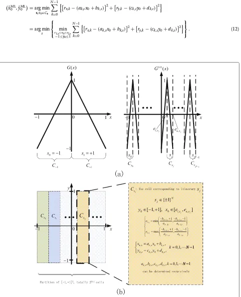
This concept is illustrated in Fig. 1. In the left part of Fig. 1a, when N = 2, the itinerary has 1 bit, i.e.,s ∈
{+1,−1}. The two corresponding cells are respectively the left and right half of the segment [−1,+1]. This concept
can all be determined as functions of sj, as shown in
Fig. 1b.
Next, we discuss decoding schemes for the above baker’s dynamic encoding system.
2.1 Maximum likelihood decoding
Under the AWGN channel assumption, the received sig-nal can be represented as
. The likelihood function of the observation sequencesrx,rywith given source(x0,y0)is
The maximum likelihood estimate of source pairxˆML0 ,yˆML0 is
The last equality emphasizes the fact that all xk,yk are
functions ofx0andy0.
ˆ
xML0 ,yˆML0 =arg min
s,x0∈Cs N−1
k=0
rx,k−(ak,sx0+bk,s) 2
+ry,k−(ck,sy0+dk,s) 2
=arg min
s ⎧ ⎨ ⎩e1,smin≤x0≤e2,s
−1≤y0≤1 N−1
k=0
rx,k−(ak,sx0+bk,s) 2+
ry,k−(ck,sy0+dk,s) 2
⎫ ⎬
⎭. (12)
Fig. 1Partition and itinerary.aWhenN=1, itineraryshas just 1 bit,+1 or−1 (left); for generalN=n+1, itineraryshas 2npatterns (right). Each
specific patternsjcorresponds to one segment (cell)Csjof the feasible region.bThe feasible region [−1,+1]2is partitioned into 2N−1cells, with each cellCsjcorresponding to one specific itinerary patternsj. The parameters in the affine representation of the codewords and the endpoints of
For any given itinerarys, the inner minimization prob-lem in Eq. (12) is convex and quadratic. Without consider-ing the constraints, its optimal solution(x∗0,s,y∗0,s)is given in a closed form
⎧ ing into account that the feasible(x0,y0)associated with
sshould lie within admissible range, a limiting procedure must be performed to obtain the solution to the inner minimization with specifics, i.e.,
xinner0,s =
Since there are totally a finite number of possible itinerary patterns, by enumerating all possible itineraries and selecting the{xinner0,s ,yinner0,s }which minimizes the outer minimization, the ML estimation of(x0,y0)is obtained as
The ML decoding scheme does not require a priori knowledge of the source’s distribution. So it is applicable regardless of the probability distribution of the source.
2.2 Minimum mean square error decoding
The ML decoding method is not optimal in the sense of mean square error performance. In this subsection, we focus on the minimum mean square error (MMSE) solu-tion to the baker’s dynamic system. The MMSE estimator is given in a general form as [21]
ˆ
XMMSE(y)=E{X|y} =
xf(x|y)dx, (15)
where X is random parameter to be determined and y is a specific realization of the noisy observationY. It is worth noting that the above general solution usually can-not result in a closed form solution for concrete problems. Fortunately, under the uniform distribution assumption of the source signal, the closed form MMSE estimator for the baker’s map can be obtained.
To provide the result of the MMSE decoder, here we introduce the following notations:
A1= as2; B1=aTs(bs−rx); C1= bs−rx2;
where the function Q(·) is the well-known Gaussian-Q function which is defined as
Q(x)
The detailed proof of the above result is rather involved and relegated to the Appendix.
2.3 Mixed ML-MMSE decoding scheme
The MMSE estimator involves highly nonlinear numerical evaluations, like the Q-function, which are computation demanding and costly for implementation. Next, we intro-duce some kind of mixed ML and MMSE estimator for the baker’s analog code.
As previously discussed, once the itinerary is given, the analog codewords can be written as an affine function in
xandyinto one vectorvand using (5), we can rewrite the baker’s dynamic system as follows:
v=
x y
=
as 0
0 cs
!
GTs
x0
y0
!
u
+
bs
ds
!
ts
=GsTu+ts, (21)
where parametersas,bs,cs, anddsare defined in (6).
Recall that in ML decoding, a detection of the itinerary scan be obtained. By substitutingsin (21) with the ML detectionˆsMLand packing the received signalsrx andry
into one vectorr = rT x,rTy
T
, (9) can be expressed in a compact form
rˆsML =r−tsˆML =GTˆsMLu. (22)
Thus, the baker’s map code is equivalent to a(2N, 2)linear analog code with encoderGs.
Now the problem to determine the source signal u
in the above equation becomes the standard minimum MSE receiving problem, whose solution is the well-known Wiener filter and given as [22]
ˆ uMMSE
ˆ
sML="GsˆMLGTˆsML+3σ2I #−1
GˆsMLrˆsML. (23)
A slicing operation then follows the above Wiener filtering to ensure the final estimates xˆML0 −MMSE and ˆ
yML0 −MMSElie inel,ˆsML,eu,ˆsMLand [−1,+1], respectively. For the mixed ML-MMSE method, ML decoding is per-formed to obtain ˆsML. Then, the Wiener filtering and limiting procedure follows. The mixed ML-MMSE decod-ing method requires a priori knowledge of the source and involves only linear computation operations.
2.4 Performance analysis
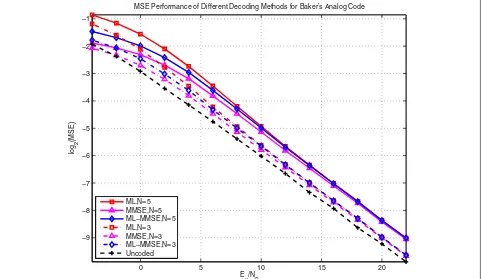
In Fig. 2, the different decoding algorithms’ performance for the baker’s analog codes with different lengths is plot-ted.Eu means the average power for each source signal,
andN0denotes the unilateral power spectral density, i.e.,
N0 = 2σ2. The ML, MMSE, and ML-MMSE decoding
algorithms have identical MSE performance for high SNR. In low SNR range, the MMSE decoding method has the best performance.
In the following, we analyze the MSE performance of the baker’s dynamic coding system by considering the Cramer-Rao lower bound. CRLB is a lower bound for the unbiased estimator [23]. It should be pointed out that the ML decoding methods discussed above are the biased estimator due to the slicing operations. However, when the SNR is large, the decoding error is sufficiently small such that the slicing rarely impacts the decoding result. So
0 5 10 15 20
−9 −8 −7 −6 −5 −4 −3 −2 −1
E
u/N0
log
2
(MSE)
MSE Performance of Different Decoding Methods for Baker’s Analog Code
ML,N=5 MMSE,N=5 ML−MMSE,N=5 ML,N=3 MMSE,N=3 ML−MMSE,N=3 Uncoded
CRLB can precisely predict the decoding error when the SNR is modestly large and is useful a tool to understand the system’s performance. This will also be verified by the following numerical results.
The Cramer-Rao lower bound forx0is given as [23]
CRLBbakerx0 = −E−x01
∂2
∂x20logp(rx,ry|x0,y0)
(24)
= −E−x01
∂2 ∂x20
$ −1 2σ2
N−1
k=0
(rx,k−ak,sx0−bk,s)2
+(ry,k−ck,sy0−dk,s)2
%
(25)
= Nσ−21 k=0 a2k,s
= 3σ2
4N−1. (26)
wherep(rx,ry|x0,y0)is defined in (10), andEx0(·)denotes the expectation with respect tox0. The recursive relations
in (6) and the facts2k=1 are used to obtain (26). Similarly, the CRLB fory0obtained as
CRLBbakery0 = −E−y01
∂ ∂y0
logp(rx,ry|x0,y0)
2
= Nσ−21 k=0 c2k
= 3σ2
4(1−(1/4)N).
(27)
WhenN is modestly large, CRLBx0 ≈ 3σ2/4N. Each increment inNcan decrease the decoding distortion ofx0
by 3/4. Comparatively, increment inN slightly improves y0 determination, which is nearly a constant as 3σ2/4 .
The CRLB reveals that the two sources are under unequal protection and there is insufficient coding gain on y0.
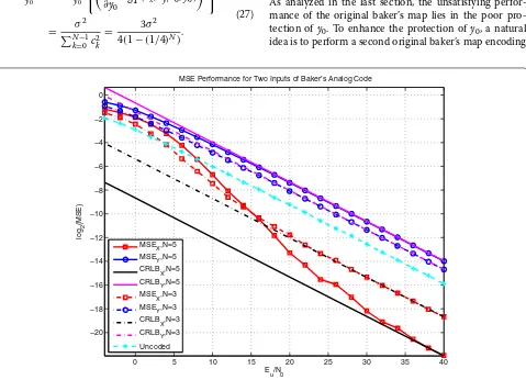
Recall that thex-sequence in codewords is obtained by continuously stretching and shifting the signal. Intuitively, the signal is locally magnified. In comparison, the y-sequence is obtained by compressing the signal. That is why the terms of 2N and 2−N appear in the denominator of CRLB forx0 andy0, respectively. This insight is
veri-fied by Fig. 3, where separate MSE decoding performances ofx0andy0 are plotted with their CRLBs illustrated as
benchmarks. Althoughx0has an obvious coding gain,y0is
poorly protected and its distortion dominates the overall decoding performance.
From the CRLB analysis, we realize that the bottleneck of the baker’s analog code lies in the weak protection to y0. Thus, to improve the baker’s map code, effective
protection should also be performed toy0.
3 Improvement I—mirrored baker’s analog code
As analyzed in the last section, the unsatisfying perfor-mance of the original baker’s map lies in the poor pro-tection ofy0. To enhance the protection ofy0, a natural
idea is to perform a second original baker’s map encoding
0 5 10 15 20 25 30 35 40
−20 −18 −16 −14 −12 −10 −8 −6 −4 −2 0
E
u/N0
log
2
(MSE)
MSE Performance for Two Inputs of Baker’s Analog Code
MSE
X,N=5
MSE
Y,N=5
CRLB
X,N=5
CRLBY,N=5 MSEX,N=3 MSE
Y,N=3
CRLB
X,N=3
CRLB
Y,N=3
Uncoded
by switching the roles of x0 and y0. Thus, both x0 and
y0 obtain balanced and effective protection. This idea
leads to the improvement scheme to be discussed in this section—the mirrored baker’s dynamic coding system. The mirrored baker’s structure comprises two branches, with its first branch being the original baker’s encoder and the second branch exchanging the roles ofx0 andy0 to
perform the original baker’s encoding for a second time. For a givenN, the mirrored baker’s system forms a(4N, 2) analog code.
Here we adjust our notations for the new system to make our following discussions clear. The two codewords associated with two branches are labeled with subscripts 1 and 2, respectively. In the first branch, x0 is the tent
map encoded and so does y0 in the second branch.
The codewords associated with x0 and y0 of the two
branches are denoted as{x1,y1}and{x2,y2}, respectively,
with their corresponding noisy observations as{r1,x,r1,y}
and {r2,x,r2,y}, respectively. The encoding procedure is
observations are represented as
rj,x,n=xj,n+nj,x,n,
rj,y,n=yj,n+nj,y,n, , j=1, 2; n=0, 1,· · ·,N−1.
(29)
The mirrored baker’s dynamic system has two itinerariess1 ands2 from the first and second branches,
respectively, the two of which compose the entire itinerary for the mirrored baker’s system. As previously discussed,s1indicates a partition of the feasible domain
ofx0. So doess2toy0. The entire feasible domain for the
source pair(x0,y0), which is a 2×2 square centered at the
origin on the plane, is uniformly divided into 2(2N−2)cells, with each cell being a tiny square having edge of length 2−(N−2). Assuming that the source(x0,y0) is known to
live in some specific cell, the itinerariess1ands2can be
determined and the codewords can be expressed as affine functions:
the first and the second branches, respectively, and can be determined recursively fork=0,· · ·,N−2 as follows:
with the starting point ⎧
admissible cell has projectionCs1 ontox0feasible domain and projectionCs2 ontoy0feasible domain, i.e.,
x0∈Cs1 =
Next, we discuss decoding methods for the mirrored baker’s dynamic system. These decoding methods are obtained by straightforwardly extending the results for the original baker’s system. In the following, main results are provided with details omitted.
3.1 ML decoding
For a given pair of sequences{s1,s2}, the optimal
solu-tion of the inner minimizasolu-tion of the above equasolu-tion is given as
followed by the hard limiter
xinner0,s1,s2 =
The ML estimation is given by selecting the(xinner0,s 1,s2,y
inner 0,s1,s2) among different itineraries{s1,s2} which minimizes the
outer minimization in (34).
3.2 MMSE decoding
To introduce the MMSE decoding results for the mirrored baker’s system, we adopt the following notations:
⎧
The calculation of the MMSE estimation still follows similar lines as discussed for the single baker’s system. The major difference is that since the sign sequence ofy0
con-tributes to the itinerary, the integration ofy0 should be
decomposed into parts over different Cs2’s. The MMSE estimation ofx0can be given as
ˆ
Similarly, the MMSE estimation ofy0for the mirrored
baker’s map code is given as follows:
ˆ
rored baker’s map system can be represented as an affine function of the original source(x0,y0). The
correspond-ing coefficients can be determined recursively by uscorrespond-ing Eqs. (31) and (32). Thus, the mirrored baker’s dynamic system can be rewritten as follows:
v=
We can first perform the ML estimation discussed in Section 3.1 and thus obtain the ML detection of the itinerary {ˆsML1 ,sˆML2 }. By taking the ML detection of the itinerary as true value, the linear MMSE estimator is invoked to estimate the original value of{x0,y0}as follows:
ˆ
4 Improvement II—single-input (1-D) baker’s analog code
Inspired by the performance analysis in Section 2.4, to enhance the original baker’s map performance, effective protection must be performed equally to all sources. Besides the mirrored structure proposed in the last section, here we propose an alternative improving strat-egy that is to feed they-sequence with input x0, which
actually forms a single-input (1-D) baker’s analog code . By feeding the two inputs of the original baker’s map with one sourcex0, the problem of poor protection ofy0
van-ishes and protection ofx0is enhanced. In other words, the
protection to all sources is equal and strengthened. Fur-thermore, another unconspicuous yet profound aspect of motivation of this 1-D scheme is that it performs a hidden repetition code of the itinerary, which is explained in full detail as follows.
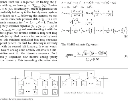
As pointed out in the papers [18] and [19], reliably deter-mining the itinerary is a key factor impacting decoding performance. In the original baker’s analog coding sys-tem, they-sequence does not help to protect the itinerary since each of its signal is uncorrelated with x0. Recall
that the codeword of they-sequence of the baker’s sys-tem is generated by the inverse tent map function using sign sequence from the x-sequence. By feeding the y-sequence with x0, we have y1 = Gsign−1(x0)(x0). Equiva-lently,x0 = G(y1). So actuallyy1can be regarded as the
state immediately beforex0in the tent dynamic system,
which we denote asx−1. Following this manner, we can
regardyias the immediate previous state ofyi−1in a tent
map dynamic sequence for i = 2,· · ·,N −1. Thus, by rewriting they-sequence signal as{yN−1,yN−2,· · ·,y0} {x−(N−1),x−(N−2),· · ·,x0} and concatenating it with the
x-sequence signals, we actually obtain a long tent map analog code (except that there are two copies ofx0here).
Moreover, this obtained equivalent tent map sequence has its special pattern: the first half itinerary is reversely identical with the second half itinerary. In other words, the 1-D baker’s analog code actually constructs a hid-den repetition code for the itinerary sequence. Both the x- and y- sequences now become analog “parity bits” of the itinerary. This interesting alternative view
of the 1-D baker’s dynamic system is illustrated in Fig. 4.
Next, sticking to the notations introduced above for the baker’s system, we give out the decoding results for this one-dimensional baker’s analog code.
4.1 ML decoding scheme
Similar to the previous discussion, for each given itinerary s, the optimal solution to inner minimization x∗0,s is obtained by
xinner0,s = ⎧ ⎨ ⎩
el,s, ifx∗0,s<el,s, eu,s, ifx∗0,s>eu,s, x∗0,s1,s2otherwise,
withx∗0,s= a T
s(rx−bs)+cTs(ry−ds) aT
sas+cTscs .
(43)
The ML estimate is obtained by going over all possible itineraries and selecting the xinner0,s which minimizes the likelihood function.
4.2 MMSE decoding scheme Defining the following parameters
A= as2+ cs2; B=aTs(bs−rx)+csT(ds−ry); C= bs−rx2+ ds−ry2;
E=exp
B2−AC
2σ2A &
; D=Q
$√
A
σ el,s+ B σ√A
%
−Q
$√
A
σ eu,s+
B
σ√A %
;
J=exp
− 1
2σ2A
el,s+ B A
2
−exp
− 1
2σ2A
eu,s+ B A
2
,
(44)
The MMSE estimate if given as
ˆ xMMSE0 =
s
2π A2E
" σ AJ−
√
2πB A3/2 D
#
s
2π
AED
. (45)
4.3 ML-MMSE decoding scheme
Assume that the ML detection of the itinerary issˆML, then
the received signal can be written in an affine form ofx0as
rx
ry
=
aˆsML csˆML
x0+
bsˆML dˆsML
. (46)
The linear MMSE estimate is obtained by performing a limiting procedure to the following value:
ˆ
xMMSE0 (sˆML)= a
T ˆ
sML(rx−bˆsML)+cTˆ
sML(ry−dˆsML) aˆsML2+ csˆML2+3σ2
.
(47)
5 Simulation results and discussions
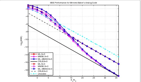
In this section, numerical results and discussions are presented. The MSE performance of ML, MMSE, and ML-MMSE decoding algorithms for mirrored baker’s and single-input baker’s system is presented in Figs. 5 and 6, respectively, whereEu represents the average power for
each source signal andN0 denotes the unilateral power
spectral density. In our experiment, the source signals are independent and uniformly distributed over [−1,+1]. For each coding system, codes withN = 3 andN = 5 are tested. The associated CRLBs (determined explicitly in Eq. (48)) and uncoded performance are plotted to serve as benchmarks. Numerical results verify the validity of the decoding algorithms developed in previous sections and
show that both of the mirrored and single-input structure have improved MSE performance of the original baker’s coding system.
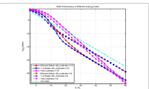
Figure 7 compares the performance of the mirrored and single-input baker’s map and the tent map analog codes proposed in [16, 17], where code rates of 1/6 and 1/10 are considered for each coding scheme. Although the tent map encoding scheme can be proved to have a lower CRLB, its actual performance is disadvantageous to the improved baker’s schemes over a wide SNR range.
Generally, the distortion of analog transmission systems can be decomposed into two parts [2]: anomalous dis-tortion and weak disdis-tortion. Weak disdis-tortion, stemming from the channel noise, can become very small and close to zero as long as the channel noise is sufficiently small. As analyzed in [13], to reduce the distortion of estima-tion, the transmitted signal must be stretched as much as possible, which can be intuitively seen as “amplifying” the signal. However, due to transmission power constraint, transmitted signals have to be bounded, and thus, the stretching cannot be arbitrarily extensive without fold-ing. This means the stretched signal will have multiple folds. The ML decoding projects the received signal to a valid codeword with minimum Euclidean distance. Pro-jection onto an erroneous fold results into an anomalous distortion, which introduces a rather notable estimation error. In practical code design, the weak distortion and
0 5 10 15 20 25 30 35
−18 −16 −14 −12 −10 −8 −6 −4 −2
E
u/N0
log
2
(MSE)
MSE Performance for Mirrored Baker’s Analog Code
ML,N=5 MMSE,N=5 ML−MMSE,N=5 CRLB,N=5 ML,N=3 MMSE,N=3 ML−MMSE,N=3 CRLB,N=3 Uncoded
0 5 10 15 20 25 30 35 −18
−16 −14 −12 −10 −8 −6 −4 −2
E
u/N0
log
2
(MSE)
MSE Performance for 1−D Baker’s Analog Code
ML,N=5 MMSE,N=5 ML−MMSE,N=5 CRLB,N=5 ML,N=3 MMSE,N=3 ML−MMSE,N=3 CRLB,N=3 Uncoded
Fig. 6MSE performance of different decoding algorithms for the single-input baker’s analog code
0 10 20 30 40 50 60
−25 −20 −15 −10 −5
Eu/N0
log
2
(MSE)
MSE Performance of Different Analog Codes
Mirrored Baker−ML,coderate=1/10 1−D Baker−ML,coderate=1/10 Tent,coderate=1/10
Mirrored Baker−ML,coderate=1/6 1−D Baker−ML,coderate=1/6 Tent,coderate=1/6 Uncoded
the anomalous distortion are two competing aspects— lengthening the codeword curve will relieve the weak distortion but will inevitably introduce more folds and a narrower space between folds and hence a higher chance for anomalous distortion; likewise, shortening the code-word curve will reduce the chance for anomalous distor-tion but increase the weak distordistor-tion. The key is to strike a best balance between these competing factors.
Specifically, the weak error can be accurately character-ized by the CRLB, and the anomalous error can be roughly indicated by the BER.
The CRLB forx0andy0of the mirrored baker’s system
is given in the following, which is also CRLB of the single-input baker’s code
CRLBmirrorx0 = −E−x01 ⎧ ⎨ ⎩ $
∂2
∂x2 0
logp(r1,x,r1,y,r2,x,r2,y|x0,y0)
%2⎫⎬
⎭
= N−1 σ2
k=0 a21,k+
N−1
k=0 a22,k
= N−1 σ2
k=0 22k+
N−1
k=0 2−2k
= 3σ2
4N−41−N+3 =CRLB mirror
y0 =CRLB 1−d y0 .
(48)
For comparison,the CRLB for the tent map code code rate 1/(2N)is given as
CRLBtentx0 = 3σ
2
42N−1. (49)
It is not hard to verify the fact that
CRLBxtent0 <CRLBmirrorx0 =CRLBx10−d,∀N∈N+. (50)
This means under equal bandwidth expansion (or code rate), the tent map system will always have a lower weak distortion.
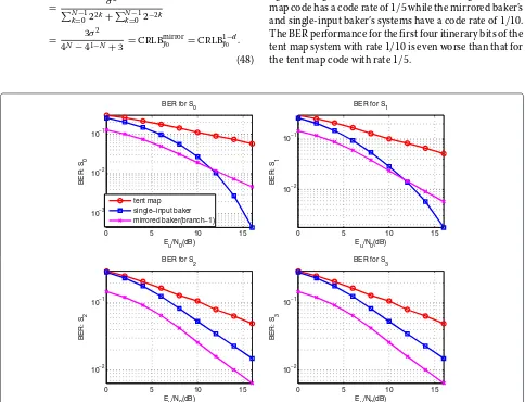
For tent map and baker’s map coding systems, itinerary errors cause anomalous distortion. To compare the anomalous distortion of different analog coding systems, we examine the bit error rate (BER) performance of the itinerary bits for each code. We test the tent map code, mirrored baker’s code, and single-input code withN=5, each of which has itinerary length of 4. The BER of each itinerary bit for different systems is illustrated in the sub-figures in Fig. 8. It should be noted that in Fig. 8, the tent map code has a code rate of 1/5 while the mirrored baker’s and single-input baker’s systems have a code rate of 1/10. The BER performance for the first four itinerary bits of the tent map system with rate 1/10 is even worse than that for the tent map code with rate 1/5.
0 5 10 15
10−3 10−2 10−1
Eu/N0(dB)
BER: S
0
BER for S0
0 5 10 15
10−2 10−1
Eu/N0(dB)
BER: S
1
BER for S1
0 5 10 15
10−2 10−1
Eu/N0(dB)
BER: S
2
BER for S2
0 5 10 15
10−2 10−1
Eu/N0(dB)
BER: S
3
BER for S3 tent map
single−input baker mirrored baker(branch−1)
From the figures in Fig. 8, the mirrored baker’s map code and single-input baker’s map code have obvious advantage in the itinerary BER performance. The mirrored structure exhibits equal protection for different itinerary bits, and the BER decays with steeper slope than that of the tent map code. Comparatively, the single-input baker’s system presents an unequal protection of different itinerary bits. The BER for itinerary bits with smaller indices decays much faster than that with larger indices. Since errors in itinerary bit with smaller index cause more serious dis-tortion, the single-input baker’s system performs a clever unequal protection to itinerary bits adaptive to their significance. This also explains the single-input baker’s map code’s advantageous performance over the mirrored baker’s map code in the medium SNR range.
From the above comparison, it can be seen that although the improved baker’s analog codes have larger weak dis-tortion than the tent map code, their anomalous disdis-tortion has been effectively suppressed. The modified baker’s map codes achieve a better balance between the protection against two kinds of distortion and consequently outper-form the tent map code in a wide SNR range.
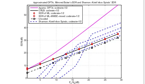
Next, we compare the baker’s map code with optimum performance theoretically attainable (OPTA) and existing analog coding schemes in literature [12–14]. OPTA can be obtained by equating the rate distortion function with
the channel capacity. From [24], we know that the rate dis-tortion function depends on the source distribution and usually does not have a closed-form expression. One of the few exceptions is the Gaussian source, whose distortion function can be obtained analytically (Theorem 13.3.2 in [24]). In the Gaussian case, OPTA can be obtained in a closed form and this is part of the reasons why the exist-ing literature tends to choose Gaussian sources as the case of study, like [12–15] do. However, Gaussian sources can-not be fed directly to the family of baker’s map encoders, whose inputs are required to be bounded ([−1,+1]). Nev-ertheless, to make our proposal comparable with OPTA and other previous works, we perform the comparison in an approximated manner by using a truncated Gaus-sian source. The source signal is first generated from the Gaussian distributionN(m,σ2) = N(0,(1/3)2). We then truncate it using a limiting range of 3σ = 1, such that 99.7 % of the probability mass falls in the region of [−1,+1]. The signal value is set as +1 if it exceeds+1, and −1 if it drops below −1. We performed mirrored baker’s coding on this truncated Gaussian source, and the results are shown in Fig. 9. It should be noted that in the figure, the OPTA bound is calculated with the true Gaussian source (the only source that is analyti-cally tractable). Since the simulated coding schemes use a truncated Gaussian source, we therefore see a small
5 10 15 20 25 30
0 10 20 30 40 50
E u/N0(dB)
SDR(dB)
Approximated OPTA, Mirrored Baker’s SDR and Shannon−Kotel’nikov Spirals’ SDR
Approx. OPTA: coderate=1/2 CRLB: coderate=1/2 SDR of ML: coderate=1/2
SDR of ML−MMSE−mixed: coderate=1/2 Uncoded
Shannon−Kotel’nikov Spirals, coderate=1/2
discrepancy, and the baker’s code actually appears to slightly outperform the OPTA at the low SNR region. At the same time, we also plot the series of the Shannon-Kotel’nikov spirals with parameters optimized for dif-ferent channel SNR (Fig. 9 in [12]). It should be noted that the MSE performance of the mirrored baker’s code and Shannon-Kotel’nikov spirals in Fig. 9 are obtained by the ML method, which can be improved by the MMSE method according to [14] and our previous discussion.
The advantage of the parameterized Shannon-Kotel’nikov spiral curve approach is that by optimizing the parameters with respect to the source distribution and the channel condition, the performance of the code can be made within some 5 dB from the OPTA [12]. The cost, however, is that one must know the exact source dis-tribution and the accurate SNR information. As shown in Fig. 9, each curve represents a Shannon-Kotel’nikov spiral with its parameter optimized towards one specific chan-nel SNR. Every time the chanchan-nel condition changes (i.e., a different SNR), the parameter(s) must be adapted or the code will suffer from a quick performance deterioration due to channel mismatch.
The proposed baker’s analog codes do not require the knowledge of the source distribution nor the channel SNR in order to perform encoding and ML decoding. Instead of designing a sequence of codes, the one optimized for each channel SNR in [12], in our approach, a single code is used for a wide range of SNR range. Figure 9 reflects that our proposal’s SDR (in dB) has identical slope for high channel SNR, or diversity, as that of optimized Shannon-Kotel’nikov spirals. The improved baker’s analog codes universally outperform the Shannon-Kotel’nikov spirals optimized for low-channel SNR and have obvious advan-tage in the low SNR range for all Shannon-Kotel’nikov spirals. Additionally, the ML decoding algorithm of our proposed chaotic analog codes has simple closed-form expression, which is absent for spiral codes.
Last, we compare the proposed analog encoding sys-tem with the conventional digital encoding syssys-tems for analog signal transmission. In our experiment, the source signals are uniformly distributed between the range [−1,+1]. For digital systems, uniform quantization and turbo codes with recursive systematic convolutional code "
1,1+1D++DD+2D+3D3 #
are used. The BCJR (log-MAP) algorithm with eight decoding iterations is performed for decoding the turbo code. Uniform puncturing is utilized to appro-priately adjust the code rate when applicable. Due to the different significance of bits obtained by quantization, equal error protection (EEP) and unequal error protection (UEP) are considered. The details of the tested systems are given as follows:
1. Analog:(6, 2)analog code is used by utilizing the mirrored baker’s code withN=2and puncturing
the system signals(y0,x0)for the second branch.
Assuming that codewords are transmitted using in-phase and quadrature forms (which can be regarded as∞-QAM modulation), the system has bandwidth expansion of3/2.
2. Digital-EEP: 8-bit quantization,(3072, 2048, 2/3) turbo code, and 256-QAM are used. System bandwidth expansion is3/2.
3. Digital-UEP1: 8-bit quantization is performed. The four least significant bits (LSB) are left uncoded. The four most significant bits (MSB) are encoded by
(4096, 2048, 1/2)turbo code. Both the coded and uncoded bits are 256-QAM modulated. System bandwidth is3/2.
4. Digital-UEP2: 8-bit quantization is performed. The two LBS are uncoded. The six MSB are encoded by
(3410, 2046, 3/5)turbo code. All bits are 256-QAM modulated. System bandwidth is3/2.
5. Digital-UEP3: 8-bit quantization is performed. The four LSB are uncoded. The four MSB are encoded by
(2560, 2048, 4/5)turbo code. The coded and uncoded bits go through 64-QAM modulation. System bandwidth is3/2.
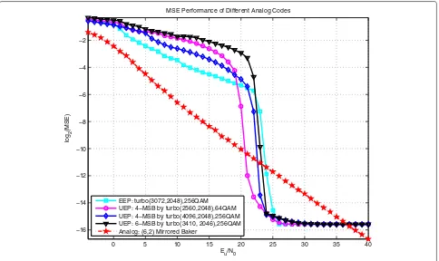
The performance of the proposed analog and four dig-ital systems is plotted in Fig. 10. The proposed analog code exhibits an obvious advantage to the digital competi-tors over a wide range when SNR has low and medium values. The digital systems enter their waterfall region at rather high SNR and exhibits error floor, which is the result of the quantization noise. In fact, due to the band-width limitation, quantization noise will always exist for the digital transmission schemes and eventually forms an error floor that limits the overall system performance even as the SNR increases to infinity. In Fig. 10, the digital coding schemes outperform the analog scheme in a narrow Eu/No range, which is due to the fact that
the digital error correction codes’ performance boosts drastically in a very narrow SNR range (the so-called waterfall region). The digital codes’ resilience to noise, although powerful, is finally suppressed by the quantiza-tion noise. Comparatively, analog coding schemes have a very graceful performance evolution, and their distortion can be made arbitrarily small if the channel is sufficiently good.
6 Conclusions
0 5 10 15 20 25 30 35 40 −16
−14 −12 −10 −8 −6 −4 −2
Eu/N0
log
2
(MSE)
MSE Performance of Different Analog Codes
EEP: turbo(3072,2048),256QAM UEP: 4−MSB by turbo(2560,2048),64QAM UEP: 4−MSB by turbo(4096,2048),256QAM UEP: 6−MSB by turbo(3410, 2046),256QAM Analog: (6,2) Mirrored Baker
Fig. 10Analog signal transmission system vs digital system
on that, two improvement encoding schemes are proposed—mirrored baker’s and single-input baker’s system. These two schemes provide sufficient protection to all encoded analog sources. The various decoding methods for the original baker’s coding system are extended to the modified systems. Compared to the classical tent map analog code, the improved baker’s map encoding schemes achieve a better balance between the anomalous and weak distortion and have advantageous performance in a wide practical SNR range. Moreover, our improved encoding schemes also exhibit competition or even better performance than the classical analog joint source-channel coding scheme, especially in the low SNR range, while maintaining much lower complexity in the decoding procedure. We also compare the ana-log and conventional digital systems using turbo code to transmit analog source signals. The digital systems suffer from granularity noise due to quantization, large decoding latency, and threshold effect. Comparatively, the analog coding scheme has a graceful perfor-mance degradation and outperforms over a wide SNR region.
Appendix
In this appendix, we provide detailed proof of the closed-form solution of the MMSE decoder for the original baker’s map code in (19).
Following notations in Section 2, we start from Eq. (15); the MMSE estimate ofx0can be given as
ˆ
xMMSE0 =E{x0|rx,ry} = +1
−1
x0f(x0|rx,ry)dx0 (51)
=
s
Cs
x0f(x0|rx,ry)dx0 (52)
=
s
Cs
x0
f(rx,ry|x0)f(x0)
f(rx,ry)
dx0 (53)
= 1
2f(rx,ry)
s
Cs x0
+1
−1
f(rx,ry|x0,y0)f(y0|x0)dy0dx0
(54)
= 1
4f(rx,ry)
s
Cs
x0 +1
−1
f(rx,ry|x0,y0)dy0dx0
(55)
= 1
4f(rx,ry)
s
Cs
x0 +1
−1
1 √
2πσ 2N
exp
− 1
2σ2 N−1
k=0
rx,k−(ak,snx0+bk,sn)
2
+ ry,k−(ck,sny0+dk,sn)
2
In the above equations, we utilize the fact thatx0and
y0are independently uniformly distributed over the range
[−1,+1]. To proceed with the above derivation, we intro-duce some intermediate parameters as follows:
A1= as2; B1=aTs(bs−rx); C1= bs−rx2;
A2= cs2; B2=cTs(ds−ry); C2= ds−ry2;
(57)
Thus, the calculation in (51) can be further written as
ˆ
Similarly, the MMSE estimator of yˆMMSE0 can be also obtained starting from (15) and is determined as
ˆ
needs to be determined, which can be calculated as
f(rx,ry)=
tively. Here we further introduce the following notations:
E1=exp
where the function Q(·) is the well-known Gaussian-Q function which is defined as
Q(x)
notations in (17) as
I1(s)=E1
Thus, by substituting Eqs. (57), (65) and (67) into (58) and (62), we can finally obtain the MMSE estimator ofx0
andy0as follows:
The proof has been completed.
Endnote
1Here we ambiguously use the terminology partition,
since every two adjacent cells overlap with their common endpoints. But this does not harm the decoding
procedure.
Competing interests
The authors declare that they have no competing interests.
Acknowledgements
Author details
1Electrical and Computer Engineering, Lehigh University, Bethlehem, PA, USA. 2Singapore University of Technology and Design (SUTD), Singapore,
Singapore.3Computer Science and Technology Department, Tongji University, Shanghai, China.
Received: 16 January 2015 Accepted: 22 June 2015
References
1. CE Shannon, Communication in the presence of noise. Proceedings of IRE.37(1), 10–21 (1949)
2. VA Kotel’nikov,The Theory of Optimum Noise Immunity. (McGraw-Hill, New York, NY, USA, 1959)
3. JM Wozencraft,Principles of Communication Engineering. (John Wiley & Sons, Hoboken, New Jersey, USA, 1965)
4. TJ Goblick, Theoretical limitation on the transmission of data from analog sources. IEEE Trans. Inform. Theory.11, 558–566 (1965)
5. J Ziv, The behavior of analog communication systems. IEEE Trans. Inform. Theory.16, 587–594 (1970)
6. KH Lee, DP Petersen, Optimal linear coding for vector channels. IEEE Trans. Commun.24, 1283–1290 (1976)
7. Y Liu, J Li, K Xie, in46th Annual Conference on Information Sciences and Systems (CISS). Analysis of linear channel codes with continuous code space (Princeton, USA, 2012)
8. A Fuldseth,Robust subband video compression for noisy channels with multilevel signaling. (Dissertation, Norwegian University of Science and Technology, 1997)
9. S-Y Chung,On the construction of some capacity-approaching coding schemes. (Dissertation, Massachusetts Institute of Technology, 2000) 10. V Vaishampayan, SIR Costa, Curves on a sphere shift-map dynamics and
error control for continuous alphabet sources. IEEE Trans. Inform. Theory.
47, 1658–1672 (2003)
11. X Cai, JW Modestino, in40th Annual Conference on Information Sciences and Systems (CISS). Bandwidth expansion Shannon mapping for analog error-control coding (Princeton, USA, 2006)
12. F Hekland, PA Floor, TA Ramstad, Shannon-Kotel’nikov mappings in joint source-channel coding. IEEE Trans. Commun.57, 94–105 (2009) 13. PA Floor, TA Ramstad, Shannon-Kotel’nikov mappings for analog
point-to-point communications. http://arxiv.org/abs/0904.1538 14. Y Hu, J Garcia-Frias, M Lamarca, Analog joint source-channel coding using
non-linear curves and mmse decoding. IEEE Trans. Commun.59, 3016–3026 (2011)
15. G Brante, RD Souza, J Garcia-Frias, Spatial diversity using analog joint source channel coding in wireless channels. IEEE Trans. Commun.61, 301–311 (2013)
16. HC Papadopoulus, GW Wornell, Maximum likelihood estimation of a class of chaotic signals. IEEE Trans. Inform. Theory.41, 312–317 (1995) 17. B Chen, GW Wornell, Analog error-correction codes based on chaotic
dynamical systems. IEEE Trans. Commun.46, 881–890 (1998) 18. I Hen, N Merha, On the threshold effect in the estimation of chaotic
sequences. IEEE Trans. Inform. Theory.50, 2894–2904 (2004) 19. SM Kay, Asymptotic maximum likelihood estimator performance for
chaotic signals in noise. IEEE Trans. Signal Process.43, 1009–1012 (1995) 20. I Rosenhouse, AJ Weiss, Combined analog and digital error-correcting
codes for analog information sources. IEEE Trans. Commun.55, 2073–2083 (2007)
21. SM Kay,Fundamentals of Statistical Signal Processing, Volume I, Estimation Theory. (Prentice Hall, Upper Saddle River, New Jersey, USA, 1993) 22. S Haykin,Adaptive Filter Theory, 4th Ed. (Prentice Hall, Berlin, Germany,
2002)
23. HV Poor,An Introduction to Signal Detection and Estimation, 2nd Ed. (Springer, Upper Saddle River, New Jersey, USA, 1998)
24. TM Cover, JA Thomas,Elements of Information Theory. (John Wiely & Sons, Hoboken, New Jersey, USA, 1991)
Submit your manuscript to a
journal and benefi t from:
7Convenient online submission
7Rigorous peer review
7Immediate publication on acceptance
7Open access: articles freely available online
7High visibility within the fi eld
7Retaining the copyright to your article
![Fig. 1a, when N{+ = 2, the itinerary has 1 bit, i.e., s ∈1, −1}. The two corresponding cells are respectively theleft and right half of the segment [ −1, +1]](https://thumb-us.123doks.com/thumbv2/123dok_us/891612.1107278/3.595.321.478.122.162/fig-itinerary-corresponding-cells-respectively-theleft-right-segment.webp)