University of Windsor University of Windsor
Scholarship at UWindsor
Scholarship at UWindsor
Electronic Theses and Dissertations Theses, Dissertations, and Major Papers
11-7-2015
A Frontier Based Multi-Robot Approach for Coverage of Unknown
A Frontier Based Multi-Robot Approach for Coverage of Unknown
Environments
Environments
RAJA SANKAR DILEEP MUDDU
University of Windsor
Follow this and additional works at: https://scholar.uwindsor.ca/etd
Recommended Citation Recommended Citation
MUDDU, RAJA SANKAR DILEEP, "A Frontier Based Multi-Robot Approach for Coverage of Unknown Environments" (2015). Electronic Theses and Dissertations. 5490.
https://scholar.uwindsor.ca/etd/5490
This online database contains the full-text of PhD dissertations and Masters’ theses of University of Windsor students from 1954 forward. These documents are made available for personal study and research purposes only, in accordance with the Canadian Copyright Act and the Creative Commons license—CC BY-NC-ND (Attribution, Non-Commercial, No Derivative Works). Under this license, works must always be attributed to the copyright holder (original author), cannot be used for any commercial purposes, and may not be altered. Any other use would require the permission of the copyright holder. Students may inquire about withdrawing their dissertation and/or thesis from this database. For additional inquiries, please contact the repository administrator via email
A Frontier Based Multi-Robot Approach for Coverage of Unknown
Environments
by
Raja Sankar Dileep Muddu
A Thesis
Submitted to the Faculty of Graduate Studies
through the School of Computer Science
in Partial Fulfillment of the Requirements for
the Degree of Master of Science at the
University of Windsor
Windsor, Ontario, Canada
2015
c
A Frontier Based Multi-Robot Approach for Coverage of Unknown
Environments
by
Raja Sankar Dileep Muddu
APPROVED BY:
Dr. Esam Abdel-Raheem
Department of Electrical and Computer Engineering
Dr. Jianguo Lu School of Computer Science
Dr. Dan Wu, Advisor School of Computer Science
DECLARATION OF ORIGINALITY
I hereby certify that I am the sole author of this thesis and that no part of this
thesis has been published or submitted for publication.
I certify that, to the best of my knowledge, my thesis does not infringe upon
anyones copyright nor violate any proprietary rights and that any ideas, techniques,
quotations, or any other material from the work of other people included in my
thesis, published or otherwise, are fully acknowledged in accordance with the standard
referencing practices. Furthermore, to the extent that I have included copyrighted
material that surpasses the bounds of fair dealing within the meaning of the Canada
Copyright Act, I certify that I have obtained a written permission from the copyright
owner(s) to include such material(s) in my thesis and have included copies of such
copyright clearances to my appendix.
I declare that this is a true copy of my thesis, including any final revisions, as
approved by my thesis committee and the Graduate Studies office, and that this thesis
ABSTRACT
With the advent of latest technical advancements in the field of robotics, a stage
has arrived where autonomous robots are expected to help humans in tasks that
are either dangerous or too monotonous such as mining, search and rescue, floor
cleaning. All these problems are derivatives of coverage problem wherein the motto
is complete coverage of the environment in a time effective manner. Most of the
coverage methods developed till date have access to the map prior to exploration
and only few of them made use of multiple robots. In view of the drawbacks of the
existing approaches, we developed a frontier based multi robot approach for coverage
of unknown environments where map building and exploration is done simultaneously.
Individual maps from the robots are merged to form a global map. Frontiers which
are the boundaries between explored and unexplored areas are identified and the
robots are navigated toward frontiers using the proposed exploration strategy. Robot
operating System (ROS) is used for implementation and Stage is used for simulating
robots and their environments. Simulation results are obtained for proposed approach
DEDICATION
To my loving family:
Father: Sri Rama Murthy Muddu
Mother: Lakshmi Muddu
ACKNOWLEDGEMENTS
I would like to take this opportunity to convey my sincere thanks to my supervisor Dr.
Dan Wu for his guidance and support throughout my graduate studies. This work
could not have been achieved without his motivation and cooperation. I gained great
research exposure and expertise under his guidance. I also appreciate the financial
aid and computing resources he provided during my thesis.
I would like to thank members of my M.Sc. thesis committee, Dr. Esam
Abdel-Raheem and Dr. Jianguo Lu for their valuable time, suggestions and constructive
comments. In addition, I would also like to thank Mrs. Karen Bourdeau for taking
care of all the administrative stuff regarding my thesis.
My sincere gratitude goes to the ROS community for all their open source resources
and tutorials, without which this thesis couldn’t be completed in a timely and effective
manner. I would also like to thank the developers of Stage simulation software.
Finally, I would like to thank my parents for their financial support, motivation
and being there with me through all the highs and lows in my career.
TABLE OF CONTENTS
DECLARATION OF ORIGINALITY . . . iii
ABSTRACT . . . iv
DEDICATION . . . v
ACKNOWLEDGEMENTS . . . vi
LIST OF TABLES . . . xi
LIST OF FIGURES . . . xiii
1 Introduction 1 1.1 Goals . . . 3
1.2 Motivation . . . 3
1.3 Problem Statement . . . 4
1.4 Thesis Organization . . . 5
2 Literature Review 6 2.1 Autonomous Robots . . . 6
2.2 Navigation and Path Planning . . . 7
2.2.1 Map . . . 7
2.2.2 Localization . . . 10
2.2.3 Path Planning . . . 15
2.3 Autonomous Exploration and Coverage . . . 16
2.3.2 Cellular Decomposition . . . 18
2.4 Multi-Robot Coverage . . . 20
2.4.1 Coordination schemes . . . 21
2.4.2 Coverage strategies . . . 22
2.4.3 Unknown Environments . . . 23
2.5 Summary . . . 24
3 Robot Operating System(ROS) 25 3.1 Overview . . . 25
3.2 Communication Framework . . . 26
3.2.1 Nodes . . . 27
3.2.2 Messages . . . 27
3.2.3 Topics . . . 28
3.2.4 Services . . . 28
3.2.5 Parameters . . . 29
3.2.6 Master . . . 29
3.3 Development Tools . . . 29
3.3.1 rviz . . . 29
3.3.2 rqt graph . . . 30
3.3.3 rqt console . . . 31
3.4 Important ROS Stacks . . . 32
3.4.1 navigation . . . 32
3.4.2 actionlib . . . 34
3.4.3 pluginlib . . . 35
3.5 Stage . . . 35
4 Frontier Based Multi-Robot Coverage 38
4.1 Highlights of proposed approach . . . 39
4.2 Assumptions . . . 39
4.3 Coverage Algorithm . . . 40
4.3.1 Map merging . . . 41
4.3.2 Occupancy Grid update . . . 42
4.3.3 Frontier Detection . . . 42
4.3.4 Frontier Allocation . . . 43
4.4 Communication Strategy . . . 47
4.4.1 Distributed Communication . . . 47
5 Experiments and Results 48 5.1 System Setup . . . 48
5.1.1 Maps . . . 49
5.2 Coverage Results . . . 50
5.2.1 Hallway . . . 50
5.2.2 Office Environment . . . 52
5.2.3 Symmetric Hall . . . 54
5.3 Rank vs Threshold based rank . . . 55
5.3.1 Hallway . . . 56
5.3.2 Office environment . . . 57
5.3.3 Symmetric Hall . . . 58
5.4 Unknown vs Known Environment Coverage . . . 59
5.4.1 Hallway . . . 60
5.4.2 Office environment . . . 61
5.4.3 Symmetric hall . . . 61
6 Conclusion and Future Work 64
6.1 Conclusion . . . 64
6.2 Future Work . . . 65
Bibliography 67
LIST OF TABLES
5.2.1 Coverage time(sec) for Hallway. . . 52
5.2.2 Coverage time(sec) for Office environment. . . 53
5.2.3 Coverage time(sec) for Symmetric hall. . . 54
5.3.1 Percentage of area covered rank vs threshold based rank. . . 56
5.4.1 Unknown vs Known environment coverage time(sec). . . 60
LIST OF FIGURES
2.2.1 Occupancy Grid map and Blue print of the environment [12]. . . 9
2.2.2 Topological Map construction [18]. . . 10
2.2.3 Graphical representation of Localization problem [12]. . . 11
2.2.4 Localization in a sample environment [12]. . . 12
2.2.5 Graphical representation of types of SLAM [12]. . . 15
2.3.1 Coverage for semi-approximate decompositions [7]. . . 19
2.3.2 Back and forth motions[7]. . . 20
3.2.1 Communication Framework [13]. . . 26
3.2.2 StudentGrades.msg [36]. . . 27
3.2.3 Interaction between nodes [37]. . . 28
3.2.4 Sum.srv [36]. . . 28
3.3.1 Visualization of turtlebot [38]. . . 30
3.3.2 Communication graph. . . 31
3.3.3 Error console. . . 32
3.4.1 Fibonacci.action [40]. . . 35
3.4.2 Client server communication [40] . . . 35
3.5.1 Stage GUI . . . 36
4.3.1 Multi-Robot unknown environment coverage. . . 41
4.3.3 Nearest based allocation. . . 45
4.3.4 Greedy based allocation. . . 46
4.3.5 Rank based allocation. . . 46
4.3.6 Threshold based rank allocation. . . 47
5.1.1 Maps used for coverage experiments. . . 49
5.2.1 Robot’s view vs Stage GUI. . . 50
5.2.2 Coverage results for Hallway in figure 5.1.1a. . . 51
5.2.3 Coverage results for Office environment in figure 5.1.1b. . . 53
5.2.4 Coverage results for Symmetric hall in figure 5.1.1c. . . 55
5.3.1 Area covered rank vs threshold based rank. . . 56
5.3.2 Coverage results(map) for Hallway. . . 57
5.3.3 Coverage results(map) for Office environment. . . 58
5.3.4 Coverage results(map) for Symmetric hall. . . 59
5.4.1 Coverage time(sec) unknown vs known environments. . . 60
Chapter 1
Introduction
Robotics has always been a field which garners a lot of attention and admiration.
But the privilege and joy of using robots was only limited to computer scientists
until the introduction of iRobot Roomba in the past decade (2002). Roomba is an
autonomous robot activated by a single push button, cleans the floors better than
any other robot vacuum cleaners available in market today [1].
Autonomous robots exhibit the following qualities [2]
• Gain information about the environment using sensors
• Work for an extended period of time without human intervention
• Avoid harmful situations.
Current research in robotics is focused on developing autonomous robots to assist
humans tasks that are too monotonous or too dangerous. Tasks such as search and
rescue and mine sweeping [3] are in dire need of autonomous robots as they are too
dangerous for humans to accomplish. And it is always handy to have a social robot
assisting in monotonous house hold activities like floor cleaning [4].
The main objective of this problem is to completely cover the environment using the
robot’s sensors in a time effective manner.
Complete coverage is analogous to covering salesman problem [6] wherein the
prime goal is to find the best possible path to cover the entire environment. For
tasks such as search and rescue and mine sweeping to be benefited from the use of
autonomous robots, multiple robots have to be deployed. However scaling to multiple
robots does come with several issues that have to be addressed. Using multiple robots
requires [7]:
• Dedicated communication network for coordination between the robots
• Path planning algorithms
• Operating System with software libraries to interface with the robot hardware
Having the above requirements satisfied, multi robot coverage can be
accom-plished. Several coverage approaches are available in the literature [7, 8, 9, 10, 5, 11, 9],
with most of the research focused on known environment coverage i.e the environment
is known to the robots prior to the exploration. This is not practical in real world
scenarios, where we expect our robots to explore unknown environments. For search
and rescue operations, the time to map the environment and then explore can be at
the cost of valuable lives. So, there is a need of robots that can handle the dynamic
nature of the environments which further increases the complexity of the algorithm
to accomplish that. Unknown environment coverage require [12]:
• Simultaneous localization and mapping modules for individual robots
• Map merging algorithms to merge individual maps
• Centralized or distributed way to compute global map and assign exploration
As the coverage tasks are time sensitive, evaluation criteria should take into
ac-count the time taken to explore the environment. As we are dealing with multiple
robots in this work, number of robots and percentage of area covered will also be
considered. So, the key evaluation criteria are the time to explore, number of robots
used and percentage of area covered. In some cases, the cost of using large number of
robots is meager when compared to the task to accomplish, such as mine sweeping or
search and rescue. So to evaluate a coverage algorithm, the measures would be the
time taken and percentage of area covered.
1.1
Goals
The prime goal of this work is to develop a multi robot frontier based approach for
coverage of unknown environments. Recent approaches [7, 8, 9, 10, 5, 11, 9] focus
on exploration of known environments. In real world scenario, robots are expected
to handle the uncertainty and dynamic nature of the environments. To meet the
demands, a coverage approach is developed for unknown environments using multiple
robots. ROS modules are used for interfacing with robots and Stage software is
used to conduct simulations. Results are evaluated taking into consideration time to
explore and the percentage of area covered.
1.2
Motivation
Robot operating system (ROS) is an open source software framework used to interface
with the physical components of the Robot. Since its introduction in 2009, ROS
has made the lives of many computer scientists better as it made easier to program
to robots without being worried about the complex physical components. Several
coverage algorithms are devised using ROS, but very few of them are directed towards
and the complexity has increased with the introduction of multiple number of robots.
Stage is a software package available for ROS used for simulations. Stage
sim-ulates robots 100 times faster than physical implementations and has a capability
of emulating various robots, sensors and environments. Stage is the prime software
being used these days to perform simulations prior to physical implementations. The
environments and robots can be configured in Stage using world file. The field multi
robot exploration is lesser known in Stage simulations and the concept of unknown
environments makes it more intriguing.
It is shocking to know that about 10,000 people loose their lives in mine related
activities, about 30 percent of people loose their lives due to lack of rescue in a timely
manner and an individual spends on average about 4-5 hours per week in regular
household cleaning activities. Autonomous robots will do a world of good if they can
assist us in these kinds of activities.
All these aspects provide motivation to develop an approach for exploration of
unknown environments using multiple robots. The robots can start at any random
location in the environment and build their own maps. Global map is formed by
merg-ing individual maps. Robots are dispersed to unexplored areas usmerg-ing a distributed
frontier allocation strategy.
1.3
Problem Statement
To meet the demands of a reliable approach for exploration of unknown environments,
a multi robot frontier based coverage approach for unknown environments is devised.
Simulations are conducted using ROS modules and Stage. Robots designed in Stage
for simulations are equipped with laser sensors to gain information from the
envi-ronment. Individual robots are equipped with capabilities to simultaneously localize
form individual maps. The environment is represented by a occupancy grid map and
the robots are navigated to unexplored areas using a distributed frontier allocation
strategy. Frontier is nothing but the boundary between explored and unexplored
area. The time taken to explore varies depending on the type of environment and
the number of robots used. The proposed approach takes care of all the uncertainties
and successfully explores unknown environments.
1.4
Thesis Organization
The rest of the thesis is organized as follows. Chapter 2 introduces the technical jargon
in the field or autonomous mobile robots followed by an introduction to ROS and
Stage simulation software and its components in Chapter 3. Chapter 4 introduces the
multi robot frontier based approach for unknown environments. Chapter 5 presents
Chapter 2
Literature Review
Robots are mechanical agents that are programmed and designed to assist humans.
Robots can either be autonomous or semi autonomous [13]. Since the introduction of
the first autonomous robot by William Grey Walter in 1948 [14], the field of robotics
gained immense attention and has been the key field of research in institutions across
the world. Over the years several breakthroughs have been made in the field of robots
including socially assistive robots [15], search and rescue [16], mine sweeping, ocean
mapping and floor cleaning robots [9]. Current research in robotics is focused on multi
robot exploration to assist humans in dangerous and monotonous tasks. This section
provides a brief high level overview of various technicalities in the field of robotics.
2.1
Autonomous Robots
Autonomous robots are those which have the capability of accomplishing the task
assigned with a high degree of autonomy i.e ability to make decisions by themselves.
Autonomous robots posses abilities to deal with the complexity and dynamic nature
of the environments and are usually employed in dangerous tasks like mine sweeping,
search and rescue, ocean mapping or monotonous tasks like floor cleaning.
should exhibit the following qualities.
• Gain information from the environment using sensors
• Work for an extended period of time without human intervention
• Avoid harmful situations and obstacles
2.2
Navigation and Path Planning
Navigation is the most important task of the autonomous robots available in market
today. In order to successfully navigate in an environment, the robot has to sense the
environment, evade dangerous situations and have path planning modules to navigate
towards a goal. Navigation is a combination of the following tasks
• Map building
• Localization
• Path planning
Now we will discuss each component of navigation in detail.
2.2.1
Map
For an autonomous robot to explore, it should have a blue print representation of
environment to be explored. This representation is provided by a map and is
depen-dent on the type of sensors used. Thus the main goal of mapping is to have a spatial
representation of the robots environment.Typically a mapmis represented as the list
of the objects and their properties in the environment given by equation 2.1 [12].
where N is the total number of objects in the environment and each mn, with
1 ≤ n ≤ N is a property. There can be three fundamental types of maps namely
Occupancy Grid maps, Feature based maps and Topological maps.
Occupancy Grid Maps
The map is represented as a field of random variables in an evenly spaced grid [12].
Each random variable is assigned a value that represents its occupancy. The random
variable can have one of the three values free, occupied and unknown. The meaning
of each value can be summarized as follows.
Free-The space has been explored and the robot knows it is free of obstacles.
Occupied- The grid has obstacles and the robot has sensed it.
Unknown- The robot hasn’t explored the grid and has no idea of its occupancy.
As per [12], the gold standard of an occupancy grid algorithm is to compute its
posterior over the maps given data according to equation 2.2.
p(m|z1:t, x1:t) (2.2)
where m is the map z1:t are the sensor measurements until a time t, x1:t is the path
of a robot defined by a sequence of its poses.
The posterior of a map over the entire map can be given as the product of the
posteriors of each grid cell which is given by equation 2.3.
p(m|z1:t, x1:t) = Y
i
p(mi|z1:t, x1:t) (2.3)
where mi represents the binary value of the occupancy. The following figure 2.2.1
represents an occupancy grid map provided in [12]. Occupancy grid maps are easy to
construct and maintain, but are not scalable to large environments taking the time
(a) Occupancy Grid Map (b) Blue print of environment
Fig. 2.2.1: Occupancy Grid map and Blue print of the environment [12].
Feature Based Maps
This map is represented by points, lines and arcs. Feature based maps only specify
the location of objects in a map, they don’t provide any information about the free
space [12]. Here mn corresponds to features in the environment. The advantage of
this approach is that it makes easier to adjust the object positions but is not suitable
for highly unstructured environments [17]. These kind of maps are suitable for static
environments.
Topological maps
This map represents the environment in the form of graphs, while the nodes
cor-respond to the landmarks in the environment. These maps are built on top of the
grid-based maps and are partitioned by critical lines which represent narrow passages
such as doorways in the environment [18]. Heremncorresponds to locations in the
en-vironment [12]. The advantages of this approach are it permits efficient planning with
low cost but it’s difficult to accurate position in the environment [17]. The following
[18]. These maps also represent the free space in the environment.
Hybrid maps can also used for exploration which are formed by combining the
fundamental mapping paradigms. It is left to user discretion to choose the best
suitable mapping paradigm for a given environment.
Fig. 2.2.2: Topological Map construction [18].
2.2.2
Localization
Localization is the key ability that an autonomous robot has to posses in order to
successfully explore the environment. Localization or pose estimation is the problem
of estimating the pose of the Robot in a given map, which can be represented as
(x, y, z, θ) where x, y, z are the 3D coordinates and θ is the orientation. Localization
can be seen as a coordinate transformation problem, where a correspondence has to
be made between the maps global frame and the robot’s pose [12]. This can be
ac-complished by sensing the robots movements and its perceptions of the environment.
following figure 2.2.3 provides a graphical representation of the localization problem
[12] where xt is the robot’s pose, m is the map, zt and ut are the measurements and
the controls of the robot.
Fig. 2.2.3: Graphical representation of Localization problem [12].
A small illustration of the localization problem is provided in the figure 2.2.4
be-low [12]. Here the environment has three indistinguishable doors where the robot has
to localize. bel(x) represents the momentary belief andp(z|x) is the posterior belief.
Posterior belief is the probability of estimating robot’s measurementz given its
posi-tionx. Initially the robot’s momentary belief is distributed equally over environment,
only after several measurements the robot is localized.
There are various types to localization problems and their complexity depends on
their type. We will now discuss the different types of localization problems [12], so
as to provide a better picture.
Local and Global Localization
Localization can be classified as Local and Global depending ion the type of
knowl-edge available initially [12].If the robots initial pose(position tracking) is known prior
to exploration it becomes a Local localization problem. Localization in this scenario
can be achieved by accommodating the noise in the robots motion. Where as in
unknown location which makes the Global localization problem difficult to solve.
Fig. 2.2.4: Localization in a sample environment [12].
A variant of Global localization problem is available called the Kidnapped Robot
problem where the robot gets kidnapped during it operation and is placed somewhere
else in the environment. Although the robot rarely gets kidnapped in practice, this
is much difficult problem to solve than global localization as in this case the robot
Static vs Dynamic Environments
Another entity that has substantial impact on the difficulty of localization is the
type of environment. The only variable in static environments is the robot’s pose.
In another words, the objects in the environment remain stable in these types of
environments. These kind of static behaviors can be observed in assembly lines in
manufacturing industries where robots can be employed. Whereas in dynamic
en-vironments the entities in the environment move along with the robot. This makes
dynamic localization a difficult candidate to solve. Examples of dynamic
environ-ments can be our houses, mines or any place with human activity which can be
encountered by socially assistive robots.
Passive vs Active approaches
Another entity that has impact on localization is whether the localization module
controls the robot. In passive approaches, localization module is limited to observing
the robot’s motion and cannot control it. However active localization approaches
have control over the robot’s motion, which results better localization. But active
robots have a drawback that they need the robot to localized at every point of time
even though the robots are busy in some exploration task.
Single vs Multiple Robots
The complexity of the localization is also dependent on the number of robots
em-ployed. In single robot localization, only one robot is operating in the environment.
So the problem boils down to localizing only that robot. Whereas multi robot
local-ization deals with multiple number of robots. This can be solved by employing single
robot localization to each robot. However better results can be obtained if the robots
Simultaneous Localization & Mapping (SLAM)
The fundamental goal of the autonomous robots these days is to learn maps and
explore unknown environments [19]. This problem is termed as Simultaneous
Local-ization and mapping(SLAM). SLAM also known as concurrent mapping and
local-ization(CML) is witnessed in situations where the robots neither have the map of
the environment nor their own pose [12], thus the robot has to build the map and
localize itself simultaneously using its measurementsz1:tand controlsu1:t. SLAM can
be formulated as the estimation of the posterior(xt) along with its map(m), given its
measurements and controls as per equation 2.4 [12].
p(xt, m|z1:t, u1:t) (2.4)
Depending on the kind of posterior being estimated, SLAM can be classified into
On-line SLAM and Full SLAM. Online SLAM is estimating the posterior over the
momentary pose as given by equation 2.4, Whereas Full SLAM is estimating the
posterior over the robot’s path in the map as given by equation 2.5. A graphical
representation of these two types of SLAM is provided in Figure 2.2.5
p(x1:t, m|z1:t, u1:t) (2.5)
Fast SLAM algorithm is another well known variant of SLAM available which uses
Rao-Blackwellized particle filters to represent its posterior over the variables [12]. In
this algorithm, each particle represents an estimate for the robots path. As the
par-ticles are conditionally independent, mapping problem can be factorized into several
sub problems, one per feature in the map. Fast SLAM solves Full SLAM problem as
it is formulated in a way that the full path posterior is calculated. In the process,
online SLAM problem is also solved as Fast SLAM estimates one pose at a time. Fast
(a) Online SLAM (b) Full SLAM
Fig. 2.2.5: Graphical representation of types of SLAM [12].
This representation is advantageous for environments that are arbitrary and without
predefined landmarks.
2.2.3
Path Planning
Path planning is to device a plan to navigate a robot from its current position towards
a goal. Path planning can be divided into two types namely global path planning
and local path planning [20].
Global Path Planning
For this variant, prior knowledge of the environment should be available i.e the map
should be available prior to the exploration. There are various global path planning
algorithms amongst which Dijkstras and A* algorithms [15] are well known. Dijkstras
algorithm, marks all the initial neighbors of the robot with the cost associated to get
there. Then the robot progresses by selecting the path with lowest cost associated
until the goal has been reached. A* algorithm considers the cost associated with
getting there along with the total cost to the goal to devise the path. Given the path,
velocity commands are sent to drive the robot towards the goal by evading obstacles.
Local Path Planning
Local path planning is mainly used for exploration of unknown environments. Here
ac-commodate to the dynamic nature of environments. Usually in local path planning,
robots are navigated in the shortest path(straight line) towards the goal until an
ob-stacle has been sensed [11]. Once sensed, the robot evades the obob-stacle and updates
the information. There are various local path planning approaches available including
potential fields and dynamic window based approach(DWA) [21]. In potential fields,
an artificial potential field is created which attracts the robots towards the goal by
repelling it from the obstacles. In dynamic window based approaches, a cost
func-tion is computed which encodes the cost of traveling towards the goal in all possible
paths. The DWA approach selects the most cost effective path and send the velocity
commands to navigate the robot towards the goal.
From the insight provided in this section it can be inferred that map building,
localization and path planning are the key components required by an autonomous
robot in order to navigate successfully. Although there are numerous permutations
possible for selecting each module, the type of environment plays a key role in deciding
the best fit. Therefore the best suitable map building, localization and path planning
modules are selected depending on the robot’s environment and its applications.
2.3
Autonomous Exploration and Coverage
The major applications of autonomous robots lies in exploration and coverage of
unknown environments [22]. Exploration is searching for valuable information using
the robot’s sensors. In case of coverage, the exploration has to be performed over the
entire environment. Robots explore the environments using their sensors. Depending
on the type of sensors equipped and the type of robot, there can be several applications
like mine sweeping, oceanographic mapping, search and rescue, floor cleaning, lawn
mowing, painting, etc.. All these operations come under complete coverage, wherein
algorithms are based on start-goal problems where the best possible path is computed
towards the goal [7]. But the coverage problems described above require much more
than a path towards the goal. Coverage is analogous to covering salesman problem, a
variant of traveling salesman problem where the agent has to travel the neighborhood
of the city as opposed to just visiting the city as in traveling salesman problem [6].
2.3.1
Traditional Coverage approaches
The early works in autonomous coverage include Heuristic and Random approaches.
Although these are easy to implement, they are not successful in providing a provable
guarantee for complete coverage of the environment.
Heuristic Approaches
Heuristics are set of behaviors that robot’s exhibit such as following a wall or evading
obstacles [23]. A hierarchy of such behaviors can make the robot capable of
accom-plishing complex tasks like exploration. One heuristic available is the repulsion of
other robots, where the robots keep repelling each other until an equilibrium has
been reached. This heuristic when combined with avoid obstacle helps the robots in
exploration. Heuristic approaches fail to provide a provable guarantee for complete
coverage and consume valuable computational resources.
Random Approaches
In these approaches, the robots explore the environment in a random manner.
Ran-dom approaches don’t guarantee complete coverage either, but are advantageous over
Heuristic approaches as they do not consume valuable computational resources.
Ran-dom methods don’t need costly sensors and complex localization modules which
con-sume valuable computational; resources. According to Gage [24], if the probability of
detecting a mine by a robot in a single pass is not 1, then its not worth choosing the
heuristic approach. The advantage of random approaches over heuristic increases as
Therefore it is better to choose a random approach for coverage if the heuristic
approaches cannot provide any guarantee complete coverage.
2.3.2
Cellular Decomposition
The best thing that the modern day robots can do is to provide a provable guarantee
for the complete coverage of the environment. This guarantee could be a great blessing
for tasks such as mine sweeping, oceanographic mapping, search and rescue and
even floor cleaning. All the coverage approaches these days provide this provable
guarantee use some kind of cellular decomposition [7]. The coverage of all the free
cells in the environments implies complete coverage. There are three types of cellular
decompositions [7]:
Approximate Cellular Decomposition
Approximate cellular decomposition is a fine grid based representation, where the
union of all the cells only approximates the environment [7]. Generally each cell is
of robot’s footprints size, so if the robot enters a cell it is covered [7]. Therefore
complete coverage is achieved if the robot visits all the free cells.
Zelinsky et al. [25] used a conventional wavefront algorithm for complete coverage.
In a wavefront algorithm, the goal is initially assigned value 0 and its surrounding
cells are assigned value 1. The cells surrounding the cells with value 1 are assigned
value 2. This process continues until the wavefront has crosses the start position.
Once this happens, the robot uses a gradient descent on values to compute the path
[26].
Semi-Approximate Cellular Decomposition
In this decomposition all the cells are of equal size but the floor and ceiling can be
of any shape. Hert and Lumelsky [27, 28] proposed a coverage algorithm based on
partial discretization of space. Here the robots can start at any random location in
un-covered areas are detected by the robot and un-covered again. The smaller areas inlets
are covered by the robot in depth first order as per figure 2.3.1. This algorithm is
suc-cessful in achieving complete coverage. The complexity of this approach is measured
by two parameters: the distance traveled by the robot and the memory required to
store input information. This approach guarantees complete coverage without any
prior information about the environment, i.e coverage can be accomplished on-line.
Fig. 2.3.1: Coverage for semi-approximate decompositions [7].
Exact cellular decomposition can be termed as a set of non intersecting regions called
cells whose union forms the environment to be covered. Each cell can be covered
using simple back and forth motions, thus coverage is reduced to planning between
cells.
Tapezoidal decomposition [29] is one amongst the popular approaches that
guar-antee complete coverage. Here the robots free space is divided into trapezoidal cells of
equal size. Coverage in each trapezoidal cell can be accomplished using simple back
and forth motions as in figure 2.3.2. Complete coverage is achieved by covering of all
the cells in the adjacency graph. Exact cellular decomposition makes the coverage
process simple and guarantees complete coverage.
Fig. 2.3.2: Back and forth motions[7].
2.4
Multi-Robot Coverage
When so much can be accomplished by a single robot in autonomous exploration
and coverage, imagine what can be achieved if we have multiple robots to serve the
purpose. The key advantage of using multiple robots is that the coverage can be
finished at a faster pace. The time taken to explore becomes really important in
It is witnessed that about 1,000 people lose their lives in mine related accidents
every year, about 50 percent of people lose their lives due to lack of rescue in timely
manner. Therefore the usage of multiple robots becomes very crucial in these kinds
of applications. although the usage of multiple robots is advantageous it does come
with some difficulties. The following are the requirements for a multi robot system
to work.
1. Communication network for coordination between the robots
2. Path planning modules
3. Centralized or distributed coordination schemes
4. Coverage strategies
Following is a brief description of the components required for the successful usage
of multiple robots.
2.4.1
Coordination schemes
There are two types of coordination schemes that can be employed by teams of
mul-tiple robots namely:
Centralized Coordination scheme
Here robot’s communicate with a centralized coordinator robot termed as the master
robot. This master robot assigns the navigation tasks to the robots and makes sure
that all the components are working properly. This strategy is advantageous and
easy to implement but there is a possibility of single point failure. If the master robot
fails, the entire system collapses and the exploration would be halted.
Distributed coordination scheme
In this scheme the robots are self reliant, they take their own navigation decisions
communicate their progress over the Wifi network. This scheme doesn’t suffer from
single point failure as there is no master coordinator. This scheme is suitable for
applications where the information is too big for a single master robot to handle.
2.4.2
Coverage strategies
There are various coverage strategies available for multiple robots. This section
out-lines the most popular coverage strategies [5] namely:
Potential Fields
In this approach the robots follow a gradient descent in a fine-grain two dimensional
grid map. Howard et al proposed a multi robot coverage approach where robots keep
repelling each other until an equilibrium has been reached. As equilibrium is not
analogous to complete coverage, this approach fails to provide a guarantee for
com-plete coverage. Although this can be resolved by introducing an overlapping potential
field where robots repel from the obstacles and are attracted to the unexplored space,
there is no guarantee for complete coverage the robots might get trapped in local
minima [30].
Graph methods
This is another popular approach where the map is represented in the form of a graph.
Edges in the graph represent the hallways and nodes represent the intersections in
the environment. Once the graph is formed complete coverage is achieved by using
traveling salesman problem [31]. The advantage of this approach is that the path
planning can be computed off-line. This approach fails to accommodate the dynamic
nature of the environments and unknown obstacles.
Frontier Methods
This is a common coverage strategy used for multiple robots. Frontier is nothing
but a boundary between the explored and unexplored space., The map is represented
[32]. Rogers et al proposed a centralized coordination strategy to dispatch the robots
to their allocated frontier. The master robot detects the frontiers and allocates them
to the robots. The frontiers are allocated to the robots in a greedy manner which
means the robots are allocated to their nearest frontiers. A dedicated wifi network is
required for this approach to work.
Rogers et al approach is extended in [8], using an approach called MinPos. In this
approach a cost map is computed based on the robot’s rank towards each frontier.
This kind of allocation makes the robots to be more dispersed in the environment.
MinPos approach doesn’t suffer from single point failure as it uses a distributed
communication strategy.
For all the frontier based approaches to work, frontiers have to identified and
clustered. There are two popular frontier identification methods available namely
Wavefront Frontier detection and digital image processing techniques. In wavefront
frontier techniques a wave front is propagated towards the goal. Image processing
technique implement complex image processing modules on the map to detect and
cluster the frontier cells.
Hybrid coordination strategies are also possible which are a combination of the
above strategies. Each strategy has its own advantages, disadvantages and
require-ments. So the best suitable strategy may be selected depending on the type of
envi-ronment to explore.
2.4.3
Unknown Environments
In real world scenario we would like our robots to explore unknown environments as
opposed to known environments. The time taken to construct a map can be costly in
applications such as mine sweeping and search and rescue. The robots should
accom-modate to the dynamic nature of the environments and unknown map. Following are
1. Centralized or decentralized coordination between the robots
2. Map merging modules to form the global map which is a combination of
indi-vidual maps from the robots
3. Simultaneous Localization and Mapping modules for individual robots
2.5
Summary
This chapter has provided a detailed overview of the technical jargon in the field of
robotics. Given the application of the robots, the best suitable modules are selected
Chapter 3
Robot Operating System(ROS)
ROS is an open source framework [13] that aids in development of various robot
applications. ROS serves as an bridge between the physical components, sensors of
the robot and the operating system. Thus the user can program the robot to exhibit
various behaviors without being bothered about its hardware components. ROS is
designed to work with physical robots as well as simulated robots. Stage is a software
framework that can simulate most of the sensors and robots available in market today
[33]. Stage has been extensively used in our approach to conduct simulations. ROS
Indigo [34] distribution on Ubuntu 14.04 operating system is used to program the
complex various behaviors of the robots. This chapter provides a brief overview of
the Robot Operating Systems(ROS) and the Stage simulation software and their
components.
3.1
Overview
Autonomous Robots are getting more and more complex these days using various
types of sensors and motors [20]. Therefore the demand for a framework that
inte-grates the sensors and all the hardware components of the robot with an operating
robot’s hardware components with operating system, thus eliminating the time to
integrate the hardware and making it easier for a novice user. ROS is also
popu-lar as a meta-operating system that provides tools and libraries to help the users
develop complex robotic applications. ROS supports parallel computing and
dis-tributed communication framework. The individual components in an application
can interact using ROS without being constrained to run on a single computer.
Although there are various robot frameworks such as Player, YARP, Orocos,
CAR-MEN, Orca, MOOS, and Microsoft Robotics Studio available, ROS has gained
atten-tion due to its distributed nature, code re-usability and community support.
3.2
Communication Framework
ROS uses divide and conquer strategy while designing complex robot applications
[5]. Packages with individual executable entities called nodes are the fundamental
components of ROS. The key idea behind this is to emulate operating system like
behavior while promoting code reuse and distributed communication. Packages with
common goals are grouped as stacks. Each package has a manifest(package.xml) that
describes its functionality and dependencies on other packages. Nodes in package
communicate with each other by passing messages using topics. The following Figure
3.2.1 represents the typical communication framework in ROS.
3.2.1
Nodes
Nodes are individual processing modules in ROS. Usually ROS comprises of many
processing nodes each assigned specific set of tasks. For example, a simple navigation
task can have various nodes to perform path planning, processing sensor data,
ob-stacle avoidance, controlling wheel motors and so on. All the nodes accomplish their
assigned tasks and communicate with other nodes by passing messages over topics
[5]. ROS nodes are written using client libraries roscpp or rospy [35].
roscpp: This is a C++ library designed to be a high performance client library used
widely in the ROS community.
rospy: This is a Python library designed to provide the advantages of object oriented
scripting language to ROS. Most of the core ROS tools such as roslaunch, ROS
Mas-ter, etc are designed using rospy taking into consideration its quick implementation
speed.
There are various other experimental client libraries available such as roscs, roseus,
rosgo, roshask, rosjava, rosruby etc which can be used based on the application.
3.2.2
Messages
Messages are simple text files comprising data fields. ROS supports Standard data
types integer, float, boolean as well as arrays of primitive types. ROS provides various
commonly used messages, the user can can also define messages by creating a .msg
file. The figure 3.2.2 shows how a typical msg file looks like.
3.2.3
Topics
Nodes publish their messages over topics. Nodes interested in the data published,
subscribe to the topics. At a given point of time a node can publish/subscribe to any
number of topics [37]. Publishers and subscribers are decoupled and in general have no
knowledge of each others existence. The following figure 3.2.3 shows communication
between two nodes.
Fig. 3.2.3: Interaction between nodes [37].
3.2.4
Services
While publish/subscribe model is based on asynchronous communication, services
provide synchronous communication between the nodes. Services are based on client/server
model where a node(client) requests for a service, another node (server) processes the
request and sends its response. Services are suitable for distributed systems, which
are based on request/reply interactions. Service definition is similar to message but
has two components request and a response. The following figure 3.2.4 shows how a
typical .srv file would look like.
3.2.5
Parameters
ROS stores all the shared parameters in a parameter server, accessible to all the
nodes. Usually shared information such as map, number of robots etc is stored in the
parameter server. Parameter server is part of the ROS Master.
3.2.6
Master
ROS master is the key component without which nodes cannot communicate or
ex-change messages. Master takes care of name registration and lookup [37].
3.3
Development Tools
ROS provides various tools [13] for visualization and debugging to assist programmers
in developing robotic application. Following are the tools used in developing our
frontier based coverage.
3.3.1
rviz
This is a 3D visualization tool available for ROS. rviz uses displays to represent the
information in 3D world. There are various built-in displays available in rviz such
as camera, image, laser scan, map, robot model, grid etc. Users can configure these
displays depending on the application. The following figure 3.3.1 represents the rviz
Fig. 3.3.1: Visualization of turtlebot [38].
3.3.2
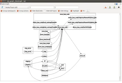
rqt graph
rqt graph is a GUI plug-in for visualizing ROS communication graph. Typically this
is the goto place for a user to get an idea of the interactions between various node.
Fig. 3.3.2: Communication graph.
3.3.3
rqt console
rqt console is a GUI plug-in for display and filter the ROS messages. Here
mes-sages are updated real time and are viewed as message, severity, node, time, topic
and location. Messages can be filtered on their severity levels. There are four levels
Fig. 3.3.3: Error console.
3.4
Important ROS Stacks
ROS provides various packages to assist in development of robotic applications. ROS
community makes sure that the packages are updated with latest implementations,
thus making it easier to a novice user to get accustomed with ROS. To develop an
application, all the programmer need to worry is to implement his implementation.
Programmers have access to ROS open source packages to configure modules such as
robot motion, path planning, visualization etc.
3.4.1
navigation
This is a two dimensional navigation stack that takes inputs odom, sensors and goal
pose and outputs velocity commands to the robot’s base [39]. Navigation stack
a few hardware requirements to use the navigation stack
• Supports differential drive and holonomic robots and velocity commands are
sent in the form of (x, y, θ)
• Requires a laser sensor mounted on the robots base for map building and
local-ization.
• Although the navigation stack works for robots of any shape, it is best suitable
for square or circular robots.
Localization
For localization, the navigation stack uses the Adaptive Monte-Carlo Localization(AMCL)
[12]. AMCL uses particle filter to track the robots position, which takes inputs laser
based map, laser scans and transform messages and outputs the robots pose estimate.
The following summarizes amcl algorithm.
1. Initially, particles are distributed over the entire space here each particle
repre-sents the pose estimate of the robot.
2. Prediction: In this phase the measurement data [∆x,∆y,∆Θ] received from
the sensors is combined with current state [ ˆxk,yˆk,Θˆk] to give new pose estimates
[ˆxk+1,yˆk+1,Θˆk+1] as per equation 3.1.
3. Update: In this phase the laser sensor is sampled and is compared with
mea-surements. Particles are weighed based on the comparison, which results in a
dense cluster of particles around the robots location.
4. The prediction and update phases are repeated continuously, thus providing
ˆ
xk+1
ˆ
yk+1
ˆ Θk+1
= ˆ
xk+ p
∆x2+ ∆y2 ∗cos( ˆΘ
k+ ∆Θ)
ˆ
yk+ p
∆x2+ ∆y2∗sin( ˆΘ
k+ ∆Θ)
ˆ
Θk+ ∆Θ
(3.1) Path planning
amcl uses a cost map based approach for path planning. Cost map is nothing but a 2
dimensional occupancy grid with each cell assigned values free, occupied or unknown.
Path planning is nothing but navigation towards a goal in a known occupancy grid
map. Path planning is divided into two components: Global Path planning and Local
path planning [39]. amcl uses A* algorithm for global path planning. A* algorithm
outputs the optimal path to the goal. Local planning takes care of the dynamic
obstacles that the global planner doesn’t consider. amcl uses a dynamic window
approach(DWA) for local planning. DWA takes care of evading the obstacles while
being intact with the global plan. The local planner outputs the velocity commands
to the robot base to navigate towards the goal.
3.4.2
actionlib
actionlib [40] stack is primarily used to interface with preamble tasks. ROS services
are suitable for request/response based tasks. But in some cases we want to receive
feedback while the server is processing the request which is provided by the actionlib
stack. actionlib provides tools to create servers for preamble servers and a client
interface to send requests to the server. ActionClient and ActionServer communicate
using ROS action protocol as per figure 3.4.2. Actions are specifies by a .action file
which specifies the Goal, Feedback and Result messages. Figure 3.4.1 demonstarates
Fig. 3.4.1: Fibonacci.action [40].
Fig. 3.4.2: Client server communication [40]
3.4.3
pluginlib
pluginlib [41] is a C++ library that helps loading and unloading plugins with a
pack-age. plugin is nothing but a dynamically loadable class at runtime. The application
using the plugin need not be aware of the the exported class, it instead gets loaded
dynamically. Pluginlib usually finds its application in situations where applications
are extended without needing their source code.
3.5
Stage
Stage is an open source software library written in C++ [33]. Stage simulates many
of the commercially available sensors and actuator models including sonar, infrared
(a) Stage GUI (b) Perspective view of Stage GUI.
Fig. 3.5.1: Stage GUI
a two dimensional bit mapped environment. Advantages of using Stage simulator
include ease of usage, simulations close to realistic robots, support for various robot
sensors, operating systems and multiple robot interactions. Stage also helps in cost
cutting and helps user to test the algorithm before implementing it on physical robots.
Stage is known to simulate a robot 1000 times faster than physical implementations.
All these advantage make Stage best candidate to use for simulations. Figure 3.5.1
represents the Stage GUI and its perspective view.
3.5.1
World File
Simulations in stage are configured using the ”.world” file. World file can be
config-ured to use various sensors and robot models, and the environment is loaded as a bit
map image. World file is programmed in C++, figure 3.5.1 represents how a world
file would look like in the GUI.
Stage is available as stage ros package for ROS[42]. Stage publishes odom, laser
scans, depth camera image and various other topics depending on the type of robot.
Stage also subscribes to the cmd vel topic published by ROS for each robot, which
replace physical robots. Therefore our frontier based unknown environment coverage
Chapter 4
Frontier Based Multi-Robot
Coverage
Coverage of unknown environments is a major problem persisting in the field of
robotics. In order to accomplish this various subproblems have to be solved, which
include robots to use Simultaneous Localization and Mapping(SLAM) modules to
map the environment, detect the frontiers, navigate towards the frontiers. An
algo-rithm should have the following capabilities to accomplish multi robot coverage for
unknown environments
• SLAM modules for individual robots
• Map merging modules to merge individual maps
• Frontier Detection
• Centralized or Decentralized frontier allocation
As there are multiple robots, frontier allocation becomes interesting. We propose an
threshold based rank frontier allocation, an extension of Rank based approach and
outlines our approach for coverage of unknown environments and all its components
map merging, frontier detection and allocation.
4.1
Highlights of proposed approach
There a very few multi robot coverage approaches [8, 22, 45, 5] in ROS. Most of the
coverage approaches are implemented for known environments, which is not practical
in real world applications. Also the existing approaches force the robots to start at
known locations in the map. Considering all these drawbacks we have proposed an
approach with the following highlights.
• Multi-Robot coverage of unknown environments
• Robots can start at random locations in environment
• Multi-Robot Coverage using ROS and simulations in Stage
• Novel frontier allocation, an extension of Rank based approach
4.2
Assumptions
The proposed approach can be extended for usage by wide variety of robotic platforms,
environments and sensors and is not bound by any assumptions. We have made
few operational assumptions to present the approach better with no impact on the
behavior of system. The assumptions are summarized as follows.
First, robots need a communication network for coordination. Second, robots are
equipped with static sensors, i.e the sensors are fixed on the robot and don’t move
while navigation, this makes it easier for map building and merging. Third, robots
build an occupancy grid map while mapping with values free, occupied or unoccupied.
unknown environments is implemented for two robots. The proposed approach can
also be extended for usage by more than two robots.
4.3
Coverage Algorithm
In our approach the robots start at random locations in the unknown environments.
Maps used in this approach are represented by occupancy grids, explained in section
2.2.1. First one robot generates an initial map, other robots localize based on the
initial map using particle filter algorithm [12]. Now the robots know the position
esti-mates of each other in the initial map, coverage can be accomplished by implementing
the following 6 modules on each robot.
1. Localize and map the environment using SLAM
2. Obtain the global map by merging individual occupancy grid maps
3. Update the occupancy grid map
4. Identify the frontiers
5. Assign frontiers to the robots using threshold based rank approach
6. Navigate robots towards the frontiers
Figure 4.3.1 demonstrates our coverage approach. As it can be seen mapping,
local-ization and navigation are provided by ROS. The following sections provide further
Fig. 4.3.1: Multi-Robot unknown environment coverage.
4.3.1
Map merging
Individual robots map the environment using Graph based SLAM algorithm [12]
also termed as Full SLAM. In this approach a sparse graph will be formed which
leads to sum of nonlinear quadratic constraints. Optimizing these constraints yields
a map with corresponding robot poses. Here the map is represented in the form
of a graph, with nodes representing pose of the robot during mapping and edges
representing spatial constraints between nodes. Figure 4.3.2 demonstrates the Graph
SLAM algorithm. Graph SLAM extracts five poses labeled x0, x1, x2, x3, x4 and two
map features m1, m2 as seen in figure 4.3.2. Each edge between the nodes represent a
nonlinear spatial constraint. To compute the map, Graph SLAM minimizes the sum
of all the spatial constraints given by equation 4.1.
JGRAP HSLAM =xT0Ω0x0+
X t
[xt−g(ut, xt−1)]TR−1[xt−g(ut, xt−1)]
+X
t
[zt−h(mci, xt)]
TQ−1[z
t−h(mci, xt)]
Graph Based SLAM is adapted to multiple robots as follows. First, one robot’s initial
map is used to localize other robots. Once the robots know each others location in the
map, global map is formed by merging individual Graph SLAM maps of the robots.
Fig. 4.3.2: Graph SLAM[12].
4.3.2
Occupancy Grid update
This module takes care of updating the occupancy grid map formed after merging
individual maps. There is no grid map initially as the exploration is for unknown
environments, thus all the cells in the occupancy grid are labeled as unknown.
Oc-cupancy grid map is updated after merging the maps and is assigned values free,
occupied or unknown depending on the map input. GridMap.cpp is the node that
shared by all the roots, i.e all the robots in the environment subscribe to the /map
topic published by the GridMap.cpp node. Therefore all the robots have the updated
map with the position estimates of the other robots in it.
4.3.3
Frontier Detection
Frontier is nothing but a boundary between explored and the unexplored area. As
the occupancy grid map is updated with the explored space, unexplored area can be
a wavefront until an unexplored cell has been reached. The detectFrontier.cpp node
on each robot subscribes to the /map topic published by GridMap.cpp and detects
and clusters the frontiers cells and are published over the topic /frontiers. Frontiers
that are adjacent to each other are clustered to avoid assigning robots to frontiers
that are observed with same perception. All the clustered cells will be covered by the
robot assigned to the frontier. FrontierAllocation.cpp node takes care of allocating
the frontiers to the robots.
4.3.4
Frontier Allocation
In this work, a new frontier allocation strategy is proposed which is an extension of
MinPos rank based frontier allocation [8]. The proposed strategy is compared with
the other benchmark frontier allocations: Nearest [43], Greedy [44] and Rank [8].
Each robot runs a FrontierAllocation.cpp node which publishes the /goal location
in the map to be explored next. The frontier allocation strategies are summarized
below.
Nearest Based Allocation
In this strategy, the robots are allocated to the nearest frontier [43]. Here the robots
do not consider other robots locations or frontiers before allocating. This kind of
allocation may result in two robots going towards the same frontier as seen in figure
4.3.3. Frontier F2 is the closest frontier for the robots 1 and 3. As this strategy
doesn’t consider the allocation of other frontiers, robots 1 and 3 would navigate
to-wards the same frontier. This might lead to overlap and considerably increase the
time to explore.
Greedy Based Allocation
Greedy based strategy allocates the robots to the nearest unassigned frontier [44].
This approach considers the locations and the frontier allocations of other robots.
fron-tier F2, robot 2 to fronfron-tier F3, robot 3 to fronfron-tier F4. Although this approach yields
better frontier assignment than nearest allocation, it might result in multiple robots
navigating towards the same region. It can observed from figure 4.3.4 that robots 2
and 3 move towards the same area in the environment.
Rank Based Allocation
Rank based allocation computes the rank of each robot towards a frontier and
al-locates the robots to frontier which is in the best position towards them [8]. Best
position means that there are lesser number of robots close by the frontier than the
robot itself. Robots are allocated to frontiers based on their position and cost. Cost
matrix C is computed, with values cost(distance) of robots towards each frontier.
The position Pij of a robot Ri towards a frontier Fj is set as:
X
∀Rk∈R,k6=i,Ckj<Cij
1 (4.2)
Equation 4.2 is the cardinal of the set of robots closer to the frontier than the robot
being assigned. Robot assignment to frontiers based on positioning rather than
dis-tance, favors spatial distribution of the robots which can be seen in figure 4.3.5. It
can be noted that robot 3 is allocated to frontier F1, even though F4 is the closest
unassigned frontier. This is because the rank for frontier F1 is 1(robot 3) and the
rank for frontier F4 is 2(robots 2,3), so the best robot for frontier F1 is robot 3.
Proposed threshold based rank allocation
Rank based allocation is extended to provide better coverage. It can be seen in the
rank based allocation that the frontier F4 is left unexplored and the robot 2 or other
robots are expected to explore it later. But the robots don’t have any track of this
frontier, and there is a possibility that this frontier could be left unexplored in large
environments. We can overcome this drawback by having the robots to keep track
based approach can be summarized as follows.
1. Frontiers are allocated to the robots using a Rank based approach.
2. Frontiers with (distance ≤ threshold distance) are marked to be explored next.
3. Robots are navigated to the marked frontiers.
4. New frontiers are detected and explored only after exploring the marked
fron-tiers.
This approach might introduce a bit of overlap but is lesser than the overlap by other
frontier allocations. Overlap results for this approach are summarized in section 5.3.
Figure 4.3.6 demonstrates the new frontier allocation, it can be seen that the robots
are allocated in the same way as in the rank based approach but the frontier F4 which
is at a distance less than the thresholdDistance is marked to be explored next. Robot
2 will move towards frontier F4 after exploring F3. This approach provides better
coverage and less overlap than the rank based allocation as discussed in section 5.3.
Fig. 4.3.4: Greedy based allocation.
Fig. 4.3.6: Threshold based rank allocation.
4.4
Communication Strategy
ROS supports two communication strategies namely: centralized and distributed.
Centralized communication strategy is easy to implement but suffers from single point
failure. If the central robot fails then the entire system fails. Also in centralized
com-munication, the robots have to wait until all the robots are assigned exploration goals.
Considering these issues, our approach uses a distributed communication scheme.
4.4.1
Distributed Communication
In a distributed setup, each robot runs the frontier exploration package individually
and maps, detects the frontiers and navigates. The robots share the Occupancy
Grid map which is formed by merging the individual maps. Each robot runs its own
FrontierAllocation.cpp and the resulting allocation will be same for all the robots. The
robots require a communication network to successfully implement the distributed
![Fig. 2.2.1: Occupancy Grid map and Blue print of the environment [12].](https://thumb-us.123doks.com/thumbv2/123dok_us/1399515.1172644/23.612.132.519.71.255/fig-occupancy-grid-map-blue-print-environment.webp)
![Fig. 2.2.2: Topological Map construction [18].](https://thumb-us.123doks.com/thumbv2/123dok_us/1399515.1172644/24.612.171.476.178.432/fig-topological-map-construction.webp)
![Fig. 2.2.3: Graphical representation of Localization problem [12].](https://thumb-us.123doks.com/thumbv2/123dok_us/1399515.1172644/25.612.227.427.156.287/fig-graphical-representation-of-localization-problem.webp)
![Fig. 2.2.4: Localization in a sample environment [12].](https://thumb-us.123doks.com/thumbv2/123dok_us/1399515.1172644/26.612.158.489.96.546/fig-localization-in-a-sample-environment.webp)
![Fig. 2.3.1: Coverage for semi-approximate decompositions [7].](https://thumb-us.123doks.com/thumbv2/123dok_us/1399515.1172644/33.612.120.530.263.660/fig-coverage-for-semi-approximate-decompositions.webp)
![Fig. 3.2.2: StudentGrades.msg [36].](https://thumb-us.123doks.com/thumbv2/123dok_us/1399515.1172644/41.612.245.407.599.677/fig-studentgrades-msg.webp)
![Fig. 3.3.1: Visualization of turtlebot [38].](https://thumb-us.123doks.com/thumbv2/123dok_us/1399515.1172644/44.612.112.538.70.355/fig-visualization-of-turtlebot.webp)

![Fig. 3.4.2: Client server communication [40]](https://thumb-us.123doks.com/thumbv2/123dok_us/1399515.1172644/49.612.254.398.71.193/fig-client-server-communication.webp)
