Closed Loop Control of PV High Voltage Gain Dc-Dc
Converter with Two Input Boost Stages
RIKKA FLORENCE
,MRS.S. SANGEETHA
2& D.S. SANJEEV
31
Mtech in Electrical and Electronic Engineering at CMR college of Engineering and
Technology
2,3
Assistant Professor in CMR college of Engineering and Technology
ABSTRACT
DC
-
DC converter is a device which produces a dc output voltage when a dc input is given.
If output voltage needed is higher than input voltage we go for boost converter.
The conventional boost converter can be used for step up applications because of low conduction loss, simple structure and low cost.
However, it is not suitable for high step-
up applications.
Generally conventional boost converters have been used to obtain higher output voltage than the input voltage.
When these boost converters are operated for high ratios it leads to high voltage and current stress on the switch.
Hence an interleaving technique of boost converter has been presented.
This method of approach can be used in high power applications to produce high voltage gain when compared to the conventional boost converter.
A simple dc-
dc boost converter is unable to provide high step-
up voltage gains due to the effect of power switches, rectifier diodes, and the equivalent series resistance of inductor and capacitors.
In this paper proposes new dc-
dc converter to achieve high voltage gain without an extremely high duty ratio.
In the proposed converters, two inductors with the same level of inductance are charged in parallel during the switch–
on period and are discharged in series during the switch-
off period.
In this converter mainly proposed converter.
That is used for PV system.
To achieve high-
voltage conversion ratios, a new family of high-
voltage-
gain dc–
dc power electronic converters has been introduced.
The proposed converter can be used to draw power from two independent dc sources as a multiport converter or one source in an interleaved manner.
They draw continuous input current from both the input sources with low current ripple which is required in many applications, e.
g.
, solar.
Several diode-
capacitor stages are cascaded together to boost up the voltage which limits the voltage stresses on the switches,diodes, and capacitors
.
In extension the input DC source is replaced with PV system and closed loop control is used to maintain output current is constantKEY WORDS
Switches, Capacitor, topology, Inductors, DC-DC power converters, High voltage gain, Non-isolated high voltage gain, DC-DC power electron converter, solar farms, and voltage 400v.
INTRODUCTION
DCDC Converters with High StepUp Gain:
circuit or dynamic clasp circuit yet the converter cost will be expanded appropriately.
High Step-up DC-DC Front END DC-AC Inverters Low Voltage DC Bus +
-VFc Vac
+
-+
-24-40VDC 380-400VDC
High Voltage DC Bus
VDC
General Power generation system with a high step-up converter
Power designing is the strategy used to supply electrical vitality from a source to its clients. It is of essential significance to industry. It is likely that the air we inhale and water we drink are underestimated until the point that they are not there. Vitality change procedure is the primary focal point of energy building. The relating hardware can be partitioned into four gatherings: AC/AC transformers AC/DC rectifiers DC/DC converters DC/AC inverters Lattice interconnection of PV/FC framework requires control converters to meet the matrix necessities like voltage adequacy, recurrence, and stage point. To start with change over the low voltage dc into high voltage dc by utilizing support dc-dc converter and afterward change over this dc voltage into air conditioning by utilizing inverters lastly interfaces the entire framework to lattice. This kind of framework (dc-dc and dc-air conditioning change) is called two phase transformation frameworks. DC-DC converters are electronic gadgets utilized at whatever point we need to change DC electrical power effectively starting with one voltage level then onto the next. They are required in light of the fact that not at all like AC, DC can't just be ventured up or down utilizing a transformer. From numerous points of view, a DC-DC converter is what might as well be called a transformer. The dc-dc converters can be seen as dc transformer that conveys a dc voltage or current at an unexpected level in comparison to the information source. Electronic exchanging plays out this dc change as in traditional transformers and not by electromagnetic means. The dc-dc converters find wide applications in controlled switch-mode dc control supplies and in dc motor drive applications.
Types of dc-dc converters:-There are a wide range of kinds of DC-DC converters, every one of which has a tendency to be more reasonable for some sort of utilizations than for others. For comfort they can be characterized into different gatherings, in any case. For instance a few converters are reasonable for venturing down the voltage, while others are appropriate for venturing it up a third gathering can be utilized for either. In this we are going to fundamental sorts of DC-DC converters.
Right now DC-DC converters can be isolated into two kind’s Non-disconnected dc-dc converters isolated dc-dc converters
Non-disconnected DC-DC Converters;-The non-disconnected converter more often than not utilizes an inductor, and there is no dc voltage segregation between the info and the yield. By far most of uses don't require dc segregation between its information and yield voltages. The non-disengaged dc-dc converter has a dc way between its information and yield. Battery-based frameworks that don't utilize the air conditioner control line speak to a noteworthy application for non-segregated dc-dc converters. Purpose of-stack dc-dc converters that draw input control from a disengaged dc-dc converter, for example, a transport converter, speak to another broadly utilized non-secluded application. Buck Converter Boost Converter Buck-Boost Converter Cuk Converter
Buck converter:-The buck converter [39] is the most generally utilized dc-dc converter topology in control Management and chip voltage-controller (VRM) applications. Those applications require quick load and line transient reactions and high effectiveness over a wide load current range. They can change over a voltage source into a lower managed voltage. For instance, inside a PC framework, voltage should be ventured down and a lower voltage should be kept up. For this reason the Buck Converter [39] can be utilized. Moreover buck converters give longer battery life to portable frameworks that invest the vast majority of their energy in "remain by". Buck controllers are regularly utilized as switch-mode control supplies for base band computerized center and the RF control intensifier (PA).
S
VS DF
Switch L L O A D IO VO + -+
-The basic schematic of a buck converter Boost converter:-A lift converter (advance up converter) is a DC-to-DC control converter with a yield voltage more prominent than its information voltage. It is a class of traded mode control supply (SMPS) containing no under two semiconductor switches (a diode and a transistor) and no short of what one imperativeness amassing segment, a capacitor, inductor, or the two in blend. Channels made of capacitors (here and there in mix with inductors) are typically added to the yield of the converter to decrease yield voltage swell.
LOAD SUPPLY
DC voltage to an alternate DC voltage is called DC to DC transformation. A lift converter is a DC-to-DC converter with a yield voltage more noteworthy than the source voltage. A lift converter is here and there rung a stage converter since it "ventures up" the source voltage. Since control (P=VI) must be bantered, the yield current is lower than the source current.
History:-For high effectiveness, the SMPS switch must turn on and off rapidly and have low misfortunes. The coming of a business semiconductor switch in the 1950s spoke to a noteworthy turning point that made SMPSs, for example, the lift converter conceivable. The significant DC to DC converters were created in the mid 1960s when semiconductor switches had turned out to be accessible. The air extension industry's requirement for little, lightweight, and productive power converters prompted the converter's fast development. Switched frameworks, for example, SMPS are a test to plan since its model relies upon whether a switch is opened or shut. R. D. Center stream from Caltech in 1977 distributed the models for DC to DC converters utilized today. Center stream arrived at the midpoint of the circuit setups for each switch state in a method called state-space averaging. This improvement lessened two frameworks into one. The new model prompted adroit plan conditions which helped SMPS development.
Applications:-Battery fueled frameworks frequently stack cells in arrangement to accomplish higher voltage. Be that as it may, adequate stacking of cells isn't conceivable in numerous high voltage applications because of absence of room. Lift converters can build the voltage and decrease the quantity of cells. Two battery-controlled applications that utilization support converters are half breed electric vehicles (HEV) and lighting frameworks.
Working rule:-The key rule that drives the lift converter is the inclination of an inductor to oppose changes in current. In a lift converter, the yield voltage is constantly higher than the info voltage. A schematic of a lift control organize is appeared in Figure 1.3 When the switch is shut, current moves through the inductor, which stores vitality from the current in an attractive field.
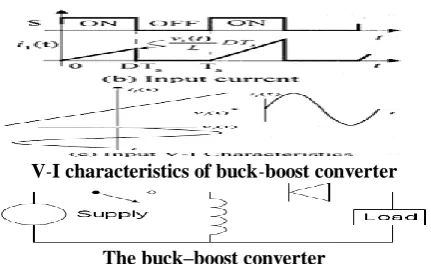
Buck-boost converters:-A fundamental buck-support converter is appeared in Fig 1.8. The normal information current of this converter can be found by its info current waveform. i_(1,avg) (t)= (D^2
T_s)/2L V_1 (t) (1.16)
V-I characteristics of buck-boost converter
The buck–boost converter
Principle of Operation: - The essential rule of the buck– support converter is genuinely basic while in the On-express, the information voltage source is straightforwardly associated with the inductor (L). These outcomes in aggregating vitality in L. In this stage, the capacitor supplies vitality to the yield stack. While in the Off-express, the inductor is associated with the yield load and capacitor, so vitality is exchanged from L to C and R. Contrasted with the buck and lift converters, the qualities of the buck– support converter are basically:
Waveforms of current and voltage in a buck– boost converter operating in discontinuous mode. Cuk converter:-The circuit setup resembles a mix of the buck and lift converters. Like the buck-help circuit it conveys an altered yield. For all intents and purposes the greater part of the yield current goes through C1, and as swell current. So C1 is generally a substantial electrolytic with a high swell current rating and low ESR (proportionate arrangement protection), to limit misfortunes. The fundamental distinction between the Cuk and alternate converters is that the Cuk utilized a capacitor as the vitality putting away component.
like these converters, it can likewise work in intermittent voltage mode (i.e., the voltage over the capacitor drops to zero amid the compensation cycle)
Vi
L1 C L2
S VS
IS
D
ID
VD CO VO
I V IC VC I
V
Cuk converter
Concept of soft switching:-In the conventional PWM converters working on hard exchanging, where the current and voltage beats goes from high to low esteem or from low to high an incentive amid the transition period, exchanging misfortune happens. Additionally produce a considerable measure of Electromagnetic interference. These misfortunes emerge on account of yield capacitor of transistor, capacitance of diode and diode turn around recuperation. From perception, it is seen that the exchanging misfortune is directly proportional to the exchanging recurrence. So the higher exchanging misfortune restricts the changing recurrence to a base esteem. Due to wide phantom scope of music introduce in PWM waveform, a high Electro Magnetic Interference (EMI) happens. Current spikes caused by Diode recuperation can likewise bring about this EMI.
Hard Switching Phenomenon
A High Step-Up Converter With a Voltage Multiplier Module for a Photovoltaic System [12]:-Sustainable wellsprings of vitality are progressively esteemed overall in view of vitality deficiency and environmental contamination. Sustainable power source frameworks create low voltage yield; in this way, high advance up dc/dc converters are generally utilized in numerous sustainable power source applications, including fuel cells, wind control, and photovoltaic frameworks. Among renewable vitality frameworks, photovoltaic frameworks are expected to assume a critical part in future vitality production. Such frameworks change light vitality into electrical vitality, and convert low voltage into high voltage by means of a stage up converter, which can change over vitality into power utilizing a lattice by-grid inverter or store vitality into a battery set. Fig.2.4 demonstrates a typical photovoltaic framework that comprises of a sun based module, a high advance up converter, a charge-release controller, a battery set, and an inverter. The high advance up converter performs importantly among the framework on the grounds that the framework requires a sufficiently high venture up change [12]. Hypothetically, regular
advance up converters, for example, the boost converter and fly-back converter, can't accomplish a high step-up transformation with high effectiveness in view of the protections of components or spillage inductance. Along these lines, a modified boost– fly-back converter was proposed, and numerous converters that utilization the coupled inductor for a significantly high voltage change proportion were likewise proposed.
Typical photovoltaic system
High step-up techniques based on a classical boost converter. (a) Integrated fly-back–boost converter structure. (b) Interleaved help converter with a
voltage-lift capacitor structure.
a) Proposed high step-up converter with a voltage multiplier module. (b) Equivalent circuit of the
proposed converter
High Step-Up High-Efficiency Interleaved Converter with Voltage Multiplier Module for Renewable Energy System [14] :-These days, sustainable power source is progressively esteemed and utilized overall on account of vitality deficiency and environmental defilement. Sustainable power source frameworks create low voltage yield, and in this way, high advance up dc/converters have been broadly utilized in numerous renewable energy applications such energy components, wind control age, and photovoltaic (PV) frameworks
Existing high step-up converter
The upsides of the proposed converter are as per the following. The proposed converter is described by low input current swell and low conduction misfortunes, which increases the lifetime of sustainable power sources and makes it suitable for high-influence applications. The converter accomplishes the high advance up pick up that sustainable power source frameworks require.
OPEN LOOP CONCEPT
photovoltaic (PV) boards, batteries, etc., to the 400-V transport in a dc micro grid framework (see Fig. 3.1) [1]– [3]. They likewise discover applications in various kinds of electronic equipment, for example, high-force release lights for car headlamps, servo-engine drives, X-beam control generators, computer fringe control supplies, and uninterruptible power supplies [4].
High-voltage-gain dc–dc converter in dc micro grid system
Mode-I:-In this mode, both switches S1 and S2 are ON. Both the inductors are charged from their information sources Vin1 and Vin2.The current in both the inductors raise directly. The diodes detached VM stages are switch one-sided and don't direct. TheVM capacitor voltages stay unaltered and the yield diode out is invert one-sided (see Fig.3.4); in this way, the heap is provided by the yield capacitor Cout.
Mode-I of operation for the existing converter with four VM stages
Mode-II:-In this mode, turn S1 is OFF and S2 is ON (see Fig.3.5).All the odd numbered diodes are forward one-sided and the inductor current IL1 moves through the VM capacitors charging the odd numbered capacitors (C1,C3,...) and releasing the even numbered capacitors (C2,C4,...). On the off chance that the quantity of VMstages is odd, at that point the yield diode Dout is turns around one-sided and the stack is provided by the yield capacitor. Be that as it may, if the number of VM stages is even, at that point the yield diode is forward biased charging the yield capacitor and providing the heap.
Mode-II of operation for the existing converter with four VM stages
Mode-III :-In this mode, switch S1 is ON and S2 is OFF (see Fig.3.6).Now, the even numbered diodes are forward one-sided and the inductor current IL2 moves through the VM capacitors charging the even numbered
Mode-III of operation for the existing converter with four VM stages
Capacitors and releasing the odd numbered capacitors. On the off chance that the quantity of VM
stages is odd, at that point the output diode Dout is forward one-sided charging the yield capacitor and supplying the heap. Be that as it may, if the quantity of VM stages is even, at that point the yield diode is invert one-sided and the heap is supplied by the yield capacitor.
Voltage Gain Of The Converter :-The charge is
exchanged logically from contribution to the yield by charging the VM organize capacitors. For a converter with four phases of VM (see Fig.3.2), the voltage pick up can be derived from the volt-sec adjust of the lift inductors. For L1, one can compose
Along these lines, from Fig.3.5, it can be watched that the capacitor voltages can be composed regarding upper lift exchanging node voltage as
Where d1 is the exchanging obligation cycle for S1.Similarly, from the volt-sec adjust of the lower leg boost inductor L2, one can compose the capacitor voltages (see Fig.3.6) in terms of lower support exchanging hub voltage as
Where d2 is the exchanging obligation cycle for S2. From (3.2) and (3.3), the capacitor voltages for the proposed converter with four VM stages can be determined as
Existing converter with N number of VM stages
T he output voltage is derived from (3.2), which is given by
Si milar analysis can be extended to a converter with N number of VM stages (see Fig.3.7). Thus, the VM stage capacitor voltages are given by
if n is odd &n ≤ N,
if n is even & n ≤ N.The output voltage equation of the converter with N number of VM stages depends on whether N is odd or even and is given by
When the converter operates in an interleaved manner with single input source, if d1 and d2 are also
chosen to be identical.e, d1 = d2 = d, then the output
voltage is given by
In [21], an interleaved support control factor rectified converter with voltage-doublers qualities is presented. It can be watched that it is an exceptional instance of the proposed converter with single VM arrange (N = 1). It is important that there is another option to the proposed converter (see Fig.3.8) where diode D1 of the main VM arrange disconnected to the lower support exchanging hub and capacitor C1is associated with the upper lift exchanging hub (think about withFig.3.7). The yield voltage condition for this elective topology is given by
For N = 1, on the off chance that one consolidates the topology delineated in Fig.3.7with its option (see Fig. 3.8), at that point the subsequent converter inFig.3.9 is like the multiphase converter presented in [22].
For the consolidated topology with a solitary info source and identical obligation proportions d1 and d2, i.e., d1= d2 = d, both the boost stages will dependably have symmetrical inductor and switch streams regardless of the quantity of VM stages.
CLOSED LOOP SYSTEM
With the expanded entrance of sustainable power sources and vitality stockpiling framework, high voltage pick up dc-dc control electronic converters find expanded application in efficient power vitality system. They can be utilized to interface low voltage sources like pv panels, batteries, etc. The fundamental question of the framework is shut circle. We will clarify that how a shut circle functions. In these we utilize PV and PI controller. in these we utilize dc-dc converter with input is dc and yield is dc To accomplish high voltage increase, traditional lift and buck-help converters require substantial switch obligation proportions. In non - disconnected it is utilized for low power application. The dc source is specifically associated with the protection. In non - disconnected in the event that we give the contribution of 20v and the rough yield voltage will get is 100-150v. We can likewise get more voltage yet we additionally exchanging misfortunes in the event that we go for non-disconnected. To dodge those exchanging misfortunes we utilize HVDC. By abstaining from exchanging misfortunes or by
controlling the exchanging misfortunes we go for non-disengaged. To accomplish high-voltage transformation proportions another group of high-voltage – pick up dc-dc control electronic converter has been presented. The proposed converter used to draw control from two autonomous dc sources as a multiport converter or one source in an interleaved way. They draw a persistent information current from both the information sources with low current swell which is required in numerous applications.
Closed loop controller:-A shut circle framework is likewise eluded as a criticism control framework. These frameworks record the yield rather than input and alter it as per the need. it produces favored state of the first one. It doesn't experience any outer or interior unsettling influence
C losed loop controller
Whatever the output we got from the shut circle it can be utilized for the heap/utility. We get 400V dc stack voltage it is utilized for electrical vehicles application the contribution of the battery is high it’s from 400V-800V. It additionally utilized for the BLDC engine drive application we can supply 400V load dc voltage it needs gigantic measure of information it works in enduring state task
MATLAB AND SIMULINK MODEL
INTRODUCTION TO MATLAB
motor, enabling access to emblematic registering capacities. An extra bundle, Simulink, includes graphical multi-area reproduction and model-based outline for dynamic and installed frameworks.
Simulink:-Simulink, created by Math Works, is a graphical programming condition for displaying, recreating and breaking down multidomain dynamic frameworks. Its essential interface is a graphical piece charting device and an adaptable arrangement of square libraries. It offers tight joining with whatever remains of the MATLAB condition and can either drive MATLAB or be scripted from it. Simulink is generally utilized as a part of programmed control and advanced flag handling for multidomain recreation and Model-Based Design.
Simulink and its Relation to MATLAB:-The MATLAB and Simulink conditions are incorporated into one element, and therefore we can analyze, recreate, and update our models in either condition anytime. We conjure Simulink from inside MATLAB. MATLAB is an intuitive programming dialect that can be utilized as a part of numerous ways, including information examination and representation, reproduction and designing critical thinking. It might be utilized as an intelligent device or as an abnormal state programming dialect. It gives a powerful situation to both the learner and for the expert architect and researcher. SIMULINKTM is an augmentation to MATLAB that gives an iconographic programming condition to the arrangement of differential conditions and other dynamic frameworks. The bundle is generally utilized as a part of the scholarly community and industry. It is especially notable in the following enterprises: aviation and resistance; car; biotech, pharmaceutical; medical; and interchanges. Authority tool stash are accessible for an assorted scope of other applications, including measurable investigation, budgetary displaying, picture preparing thus on. Furthermore, continuous tool compartments take into account on-line cooperation with designing frameworks, ideal for information logging and control.
MATLAB/SIMULINK RESULTS
EXISTING:-A dc converter with high voltage pick up and two information support arranges in open circle Existing Simulink results
In existing Simulink comes about we didn't get the correct outcomes we get inexact consequences of 380V. From 0v it ascends to around 380V then it remains always runs and it doesn't moves any point from that it stays consistent. By scooping we can see the correct voltage what we got in the open loop. To get more voltage we go for shut circle
PROPOSED CHART:-A dc-dc converter is a gadget which creates a dc yield when a dc input is given. It is a proposed chart with shut circle control of PV voltage pick up and PI controller with two information support stages.
In proposed Simulink comes about the yield simultaneously expanded from yield what we got in the open loop. in shut circle the yield from 310V is simatenously expanded to the correct voltage 400V from that it yield progressed toward becoming constant. in the shut circle the yield we got the V
-molded bend we found in the yield bend and we got the correct yield voltage 400Vthrough the shut circle.
CONCLUSION
In this undertaking, a group of novel high-voltage-pick up dc– dc converters with two lift stages at the information has been proposed. The proposed converter depends on diode– capacitor VM stages and the voltage pick up is expanded by expanding the number of VM stages. It can draw control from two information sources like multiport converter or work in an interleaved way when connected to a solitary source. One of the upsides of the proposed converter is that since it is a multiport converter with high voltage pick up, it has the adaptability to be associated with autonomous sources while permitting power sharing, MPPT algorithmsetc. to be actualized freely at each information port. Moreover, an elective topology of the proposed converter has-been introduced and joining them both would bring about a new converter topology. The proposed converter can be utilized for sun oriented applications where each board can be exclusively connected to the 400-V dc transport.
REFERENCES
[1] S. Jain and V. Agarwal, "A solitary stage matrix associated inverter topology for sun powered PV frameworks with most extreme power point following," IEEE Trans.Power Electron., vol. 22, no. 5, pp. 1928– 1940, Sep. 2007.
[2] X. Kong and A. M. Khambadkone, "Examination and usage of ahigh proficiency, interleaved current-sustained full extension converter for fuel cellsystem," IEEE Trans. Power Electron., vol. 22, no. 2, pp. 543– 550, Mar.2007.
[3] C. Liu and J. S. Lai, "Low recurrence current swell lessening techniquewith dynamic control in an energy unit control framework with inverter stack,"
IEEETrans. Power Electron., vol. 22, no. 4, pp. 1429– 1436, Jul. 2007.
[4] E. H. Ismail, M. A. Al-Saffar, A. J. Sabzali, and A. A. Fardoun, "A familyof single-switch PWM converters with high advance up transformation ratio,"IEEE Trans. Circuits Syst. I, Reg. Papers, vol. 55, no. 4, pp. 1159– 1171,May 2008.
[5] R. W. Erickson and D. Maksimovic, Fundamentals of Power Electronics,2nd ed. Norwell, MA, USA: Kluwer, 2001.
[6] W. Li and X. He, "A group of interleaved DC– DC converters deducedfrom a fundamental cell with winding-cross-coupled inductors (WCCIs) for highstep-up or advance down transformations," IEEE Trans. Power Electron., vol. 23,no. 4, pp. 1791– 1801, Jul. 2008.
[7] W. Li and X. He, "An interleaved winding-coupled lift converter withpassive lossless clasp circuits," IEEE Trans. Power Electron., vol. 22,no. 4, pp. 1499– 1507, Jul. 2007.
[8] W. Li, Y. Zhao, Y. Deng, and X. He, "Interleaved converter with voltagemultiplier cell for high advance up and high-productivity change," IEEETrans. Power Electron., vol. 25, no. 9, pp. 2397– 2408, Sep. 2010.
[9] Y.- P. Hsieh, J.- F. Chen, T.- J. Liang,and L.- S. Yang, "A novel high advance upDC– DC converter for a microgrid framework," IEEE Trans. Power Electron.,vol. 26, no. 4, pp. 1127– 1136, Apr. 2011.
[10] R. Xie, W. Li, Y. Zhao, J. Zhao, X. He, and F. Cao, "Execution analysisof disengaged ZVT interleaved converter with winding-cross-coupled inductors and exchanged capacitors," in Proc.IEEE Energy Convers. Congr.Expo., Atlanta, GA, USA, 2010, pp. 2025– 2029.
[11] W. Li, W. Li, X. He, D. Xu, and B. Wu, "General deduction lawof nonisolated high-advance up interleaved converters with worked in transformer," IEEE Trans. Ind. Electron., vol. 59, no. 3, pp. 1650– 1661, Mar.2012.
[12] K.- C. Tseng, C.- C. Huang, and W.- Y. Shih, "A high advance up converterwith a voltage multiplier module for a photovoltaic framework," IEEE Trans.Power Electron., vol. 28, no. 6, pp. 3047– 3057, Jun. 2013.
[13] W. Li, Y. Zhao, J. Wu, and X. He, "Interleaved high advance up converterwith winding-cross-coupled inductors and voltage multiplier cells," IEEETrans. Power Electron., vol. 27, no. 1, pp. 133– 143, Jan. 2012.
[15] K.- C. Tseng and C.- C. Huang, "A high advance up aloof assimilation circuitused in non-secluded high advance up converter," in Proc. IEEE Appl. PowerElectron. Conf. Expo., Long Beach, CA, USA, 2013, pp. 1966– 1971.
[16] K. Gummi and M. Ferdowsi, "Blend of twofold information DC– DC converters utilizing single shaft triple toss switch as a building hinder," in Proc.IEEE Power Electron. Spec. Conf., Rhodes, Greece, 2008, pp. 2819– 2823.
[17] V. A. K. Prabhala, D. Somayajula, and M. Ferdowsi, "Power sharing ina twofold information buck converter utilizing dead-time control," in Proc. IEEEEnergy Convers. Congr. Expo., San Jose, CA, USA, 2009, pp. 2621– 2626.
[18] S. Lee, P. Kim, and S. Choi, "High advance up delicate exchanged converters usingvoltage multiplier cells," IEEE Trans. Power Electron., vol. 28, no. 7,pp. 3379– 3387, Jul. 2013.
[19] C.- M. Youthful, M.- H. Chen, T.- A. Chang, C.- C. Ko, and K.- K. Jen, "Course Cockcroft– Walton voltage multiplier connected to transformerless highstep-up DC– DC converter," IEEE Trans. Ind. Electron., vol. 60, no. 2,pp. 523– 537, Feb. 2013.
![Fig. 3.8), at that point the subsequent converter inFig.3.9 is like the multiphase converter presented in [22]](https://thumb-us.123doks.com/thumbv2/123dok_us/1922052.1252291/6.595.311.524.329.376/fig-point-subsequent-converter-infig-multiphase-converter-presented.webp)
