IJISET - International Journal of Innovative Science, Engineering & Technology, Vol. 2 Issue 5, May 2015. www.ijiset.com
ISSN 2348 – 7968
771
Reliable Transmission of Information Over Channels
Using Cryptography and Convolutional Codes
1
.
Mahejabeen Ilkal
Electrical & Electronics dept,Bldea’s college of enggineering & technology,Vijaypur, India 586101
ABSTRACT:“Cryptography is about concealing information, and coding theory is about revealing it” Despite these apparently conflicting goals, the two fields have common origins and many interesting relationships.Shannon was the first to give cryptography a formal, mathematical treatment, focusing primarily on the task of encryption. In his model of cryptosystem, Shannon defined secrecy in terms of the amount of information a cipher-text reveals about its underlying message. To obtain perfect secrecy, a cryptosystem would need to reveal zero information about an encrypted message. A central problem of coding theory is reliable communication over an unreliable channel. All solutions to this problem, in some form or another, rely on the basic idea of encoding message with some redundancy, allowing the receiver to detect and correct whatever errors may arise during transmission through the channel. The main goal is to minimize the amount of redundancy while maximizing the quantity of errors that can be corrected.
Key words: Plain text, Cipher text, S-DEC, BEC, Viterbi, Trellis and Convolutional Code.
1.INTRODUCTION 1.1Overview
The requirements of information security within an organization have undergone two major changes in the last several decades. Before the widespread use of data processing equipments, the security of information felt to be valuable to an organization was provided primarily by physical and administrative means. An example of the former is the use of rugged filling cabinets with the combination lock for storing sensitive documents. An example of the latter is personnel screening procedures used during the hiring process. With the introduction of computers, the need for automated tools for protecting files and other information stored on the computer became evident. The generic name for the collection of tools designed to protect data and to thwart hackers is computer security. Second major change that affected security is the introduction of distributed systems and the use networks and communication facilities for carrying data between terminal user and the
computer and between computer and computer. Network security measures are needed protect data during their transmissions[1][2][3]. It is in this quest for a simple solution is to provide secure transmission of messages, that this project was under taken, its main objective is to allow two or more persons can communicate in a way that
guarantees that thedesired subset of the following four primitives,
1. Confidentiality 2. Data integrity 3. Authentication 4. Non-repudiation
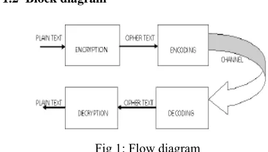
1.2 Block diagram
Fig 1: Flow diagram
1.3 Proposed Project Work
In this age of universal electronic connectivity, of the viruses and hackers, of electronic eavesdropping and electronic fraud, there is indeed no time at which security does not matter. It is in this quest for a simple solution to this problem, that this project was undertaken. The Proposed text to Conventional crypto-coding has following features, 1.The data cannot be accessed forunauthorized use. 2.The content of the data frames is hidden. 3.The authenticity of the data can be established. 4.The undetected modification of the data is avoided.
5.The data cannot be disowned by the originator of the message.
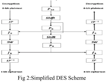
2. SIMPLIFIED DATA ENCRYPTION STANDARD
2.1(S-DES Scheme)
plaintext (e input and p output. Th 8-bit block used to p produces th
IP
this can als
Cip
Where K1= P8 (Sh
K2= P8 (Sh
Decryption essentially pla Fi fashion. as(k1,k2,k3 Then the p P10(k1,k2, ,k10,k1,k3 2.2 S-DES S-DES dep between se bit subkeys of the encr depicts th subkeys[5]
F 2.3 S-DES
example: 1011 produces an 8-he S-DES decr k of ciphertext produce that c
he original 8-b 1
2
fk P SW
so be written a
1
(
phertextIP f
hift (P10 (key)) hift (Shift (P10 n is also shown the reverse of
1
( k
aintextIP f
irst, permute Let the 10 3,k4,k5,k6,k7,k permutation P10 ,k3,k4,k5,k6,k7
,k5,k7)
Fig 2:Simplifi
S Key generati pends on the u ender and recei
s are produced ryption and de he stages fo ].
Fig 3:SDES key ge S Encryption
11101) and a 1 -bit block of c ryption algorit t and the sam cipher text a bit block of plai
1 k
W f IP
s:
2( ( 1( (
k k
f SW f IP
)) 0 (key))))
n in Figure 1 an f encryption:
2( ( 1( (
k SW fk IP c
the key in th 0-bit key b
k8,k9,k10) 0 is defined as 7,k8,k9,k10)=(
ed DES Schem
ion
use of a 10-bi iver. From this d for use in part ecryption algor ollowed to p
eneration
10-bit key as cipher-text as thm takes an me 10-bit key s input and intext. (plaintext))))) nd is text))))) ipher he following e designed (k2,k4,k6,k8 me
t key shared s key, two 8-ticular stages rithm. Figure produce the
8- bit b and pro Encryp five fun 1. An in 2. A co both p depend 3. A s (SW) th 4. The 5. A pe initial p 2.3.1 In The inp plaintex functio This re them up permut
It is eas permut is,
2.3.2 T The m functio permut functio be the bit inp necessa strings. k
f ( ,L R
Where, exclusi matrix) output, fed into two box The S-DES block of plaint oduces an 8bit ption involves
nctions. nitial permutat omplex functio ermutation an ds on a key inpu
simple permut he two halves o function
f
kag ermutation fun permutation IP nitial and Fina put to the algor xt, which we fi on:etains all 8 bits p. At the end o tation is used:
sy to show by e tation is indeed
The Function f
most complex onfk, which c
tation and ons can be expr
leftmost 4 bits put to fk,, an arily one toon . Then
) ( (
R LF R
, SK is a sub
ive-OR functio The first 4 b ) are fed into th and the rema o S1 to produc xes are defined
encryption alg text and a 10-block of ciphe the sequentia
tion (IP). on labeled
f
k, nd substitutionut.
tation function of the data. gain.
nction that is th
-1
P
al Permutatio rithm is an 8-b first permute us
of the plaintex of the algorithm
example that th d the reverse of
k f :
component of consists of a
substitution ressed as follo s and rightmost nd let F be a ne) from 4-bit
, ) )
R SK R
bkey and _ i on.
bits (first row o he S-box S0 to aining 4 bits (s
ce another 2-b d as follows:
ISSN 2348 – 79
77 gorithm takes a -bit key as inp er-text as outpu al application
which involv operations an
n that switch
he inverse of th
ons it block of sing the IP
xt but mixes m, the inverse
he second f the first; that
f S-DES is th combination functions. Th ows. Let L and
t 4 bits of the a mapping (n strings to 4-b
is the bit-by-b
of the precedin produce a 2- b second row) a bit output. The
IJISET - International Journal of Innovative Science, Engineering & Technology, Vol. 2 Issue 5, May 2015. www.ijiset.com
ISSN 2348 – 7968
773 The S-boxes operate as follows. The first and
fourth input bits are treated as a 2-bit number that specify a row of the S-box, and the second and third input bits specify a column of the S box. The entry in that row and column, in base 2, is the 2-bit output.
2.3.3 The Switch Function
The function fkonly alters the leftmost 4 bits of the input. The switch function (SW) interchanges the left and right 4 bits so that the second instance of fkoperates on a different 4 bits. In this second instance, the E/P, S0, S1, and P4 functions are the same.
2.3.3 The Switch Function
The function fkonly alters the leftmost 4bits of the
input. The switch function (SW) interchanges the left and right 4 bits so that the second instance of fk
operates on a different 4 bits. In this second instance, the E/P, S0, S1, and P4 functions are the same.
Fig 4:Example for encryption
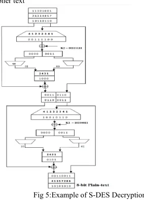
2.4 S-DES Decryption
The S-DES decryption algorithm takes an 8- bit block of cipher-text and a 10-bit key as input and produces an 8-bit block of plain-text as output. Like Encryption, Decryption also involves the sequential application of five functions.
1. An initial permutation (IP).
2. A complex function labeled fk, which involves both permutation and substitution operations and depends on a key input.
3. A simple permutation function that switches (SW) the two halves of the data.
4. The function fk again.
5. A permutation function that is the inverse of the initial permutation (IP-1).
Cipher text
Fig 5:Example of S-DES Decryption
3. BINARY SYMMETRIC CHANNEL
The BSC is a binary channel; that is, it can transmit only one of two symbols (usually called 0 and 1). (A non-binary channel would be capable of transmitting more than 2 symbols, possibly even an infinite number of choices) The transmission is not perfect, and occasionally the receiver gets the wrong bit. This channel is often used by theorists because it is one of the simplest noisy channels to analyze. Many problems in communication can be reduced due to a BSC[10]. On the other hand, being able to transmit effectively over the BSC can give rise to solutions for more complicated channels. A binary symmetric channel with crossover probability p is a channel with binary
input and binary output and probability of error p;
that is, if X is the transmitted random variable and Y the received variable, then the channel is
ISSN 2348 – 7968
774 shown in the channel diagram.
Fig 6:Channel diagram and channel matrix
It is assumed that 0 ≤p ≤ 1/2. If p>1/2, then the
receiver can swap the output (interpret 1 when it sees 0, and visa versa) and obtain an equivalent channel with crossover probability 1-p ≤ 1/2.
4. CONVOLUTIONAL CODES
Convolutional codes were first introduced by by Elias in 1955 as an alternative to block codes. Shorty there after Woaencraft proposed sequential decoding as an efficient decoding scheme for convolutional codes and experimental studies soon began to appear. In 1963, Massey proposed a less efficient but simpler to implement decoding method called threshold decoding. Then in 1967 Viterbi proposed a maximum likelihood decoding scheme that was relatively easy to implement for codes with small memory orders. This scheme called Viterbi decoding.
In “convolutional codes”, a block of n code digits generated by the encoder in a time unit depends not only the block of ‘k’ message digits within that time unit, but also on the preceding (m-1) blocks of message digits (m>(m-1). Usually the values of k and n will be small.Like block codes, convolutional codes can be designed to either detect or correct errors. However, block codes are better suited for error detection and convolutional codes for error correction.Encoding for convolutional codes can be accomplished using simple shift registers and several practical procedures have been developed for decoding[6][9].
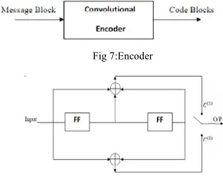
4.1 Encoder for Convolutional Codes
A convolutional encoder takes sequences of message digits and generates sequences of code digits. It is a finite state machine (FSM), processing information bits in a serial manner. Thus the generated code is a function of input and the states of the FSM.
1. ‘k’ information bits are encoded to a block of ‘n’ bits (n>k)
2. The n-digit code block depends on • ‘k’ information bits, and
• previous (m-1) information bits
3. The generated code is called an (n, k, m) convolutional code of constraint length “nm” digits and the rate efficiency will be “k/n”.
4. The encoder consists of shift registers and mod-2 adders.
Fig 7:Encoder
Fig 8:(2,1,2) convolutional encoder
4.2 Encoding of a Convolutional Code
Encoding of convolutional code is done by two approaches
1. Time domain approach 1. Convolutional method 2. Matrix method 2. Transfer domain approach
4.2.1 Time domain approach by Matrix method The time-domain behaviour of a binary convolutional encoder may be defined in terms of a set of “n impulse responses”. Let the sequence
denote the “impulse response”also called “generator sequences” for the top adder and the sequence
for thebottom adder, can be interlaced and arranged in a matrix form with ,Number of rows = number of digitsin the message sequence = L rows ,Number ofcolumns = n (L + m).Such a matrix of order [L] x [n(L + m)] is called “generator matrix” of theconvolutional encoder.
In the second row, the number of 0’s is equal to the number of modulo-2 adders. Since the generator matrix G has n (L + m) number of columns, the encoder output will have n (L + m) number of bits given by
C = d G
IJISET - International Journal of Innovative Science, Engineering & Technology, Vol. 2 Issue 5, May 2015. www.ijiset.com
ISSN 2348 – 7968
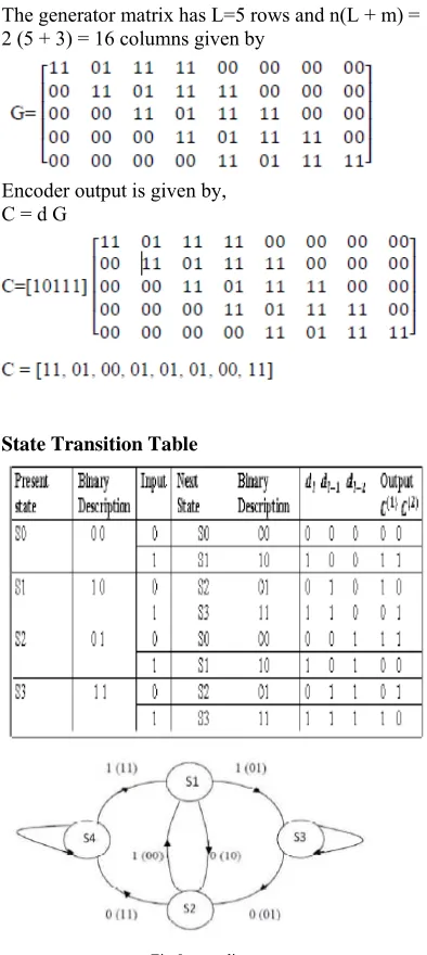
775 The generator matrix has L=5 rows and n(L + m) =
2 (5 + 3) = 16 columns given by
Encoder output is given by, C = d G
State Transition Table
Fig 9:state diagram 5. VITERBI DECODING
A Viterbi decoder uses the Viterbi algorithm for decoding a bitstream that has been encoded using Forward error correction based on a Convolutional code[7][9]. The Viterbi algorithm is the most resource-consuming, but it does the maximum likelihood decoding.
The algorithm is based on the nearest neighbour decoding scheme and, like the other algorithms we have looked at, it relies on the assumption that the probability of t errors is much greater than the probability of t+1 errors and it thus selects or chooses and retains only the paths which have fewer errors. The Viterbi algorithm was conceived by Andrew Viterbi in 1967 as a decoding algorithm for convolutional codes over noisy digital communication links. The algorithm has found universal application in decoding the convolutional codes used in both CDMA and GSM
digital cellular, dial-up modems, satellite, deep-space communications, and 802.11 wireless LANs. It is now also commonly used in speech recognition, keyword spotting, computational linguistics, and bioinformatics.
5.1 Parts of Viterbi algorithm
A Viterbi algorithm consists of the following three major parts:
1. Branch metric calculation – calculation of a distance between the input pair of bits and the four possible “ideal” pairs (“00”, “01”,“10”, “11”). 2. Path metric calculation – for every encoder state, calculate a metric for the survivor path ending in this state (a survivor path is a path with the minimum metric).
3. Traceback – this step is necessary for hardware implementations that don't store full information about the survivor paths, but store only one bit decision every time when one survivor path is selected from the two.
Fig 10: parts of viterbi algorithm
5.1.1 Branch Metric Calculation
Methods of branch metric calculation are different for hard decision and soft decision decoders.For a hard decision decoder: a branch metric is a Hamming distance between the received pair of bits and the “ideal” pair. Therefore, a branch metric can take values of 0, 1 and 2. Thus for every input pair we have 4 branch metrics (one for each pair of “ideal” values).For a soft decision decoder: a branch metric is measured using the Euclidean distance. Let x be the first received bit in the pair, y – the second,x0 and y0 – the “ideal” values. Then branch metric is
2 2
0 0
Mb(xx ) (yy )
Furthermore, when we calculate 4 branch metric for a soft decision decoder, we don't actually need to know absolute metric values – only the difference between them makes sense.
5.1.2 Path Metric Calculation
Path metrics are calculated using a procedure called ACS (Add-Compare-Select). This procedure is repeated for every encoder state.
1. Add – for a given state, we know two states on the previous step which can move to this state, and the output bit pairs that correspond to these transitions. To calculate new path metrics, we add the previous path metrics with the corresponding branch metrics.
2. Compare, select – we now have two paths, ending in a given state. One of them (with greater metric) is dropped.
ISSN 2348 – 7968
776 that the difference between two survivor path
metrics cannot exceed Δ log(k-1) , where δ is a difference between maximum and minimum possible branch metrics.The problem with path metrics is that they tend to grow constantly and will eventually overflow. But, since the absolute values of path metric don't actually matter, and the difference between them is limited, a data type with a certain number of bits will be sufficient.
There are two ways of dealing with this problem: 1. Since the absolute values of path metric don't actually matter, we can at any time subtract an identical value from the metric of every path. It is usually done when all path metrics exceed a chosen threshold (in this case the threshold value is subtracted from every path metric). This method is simple, but not very efficient when implemented in hardware.
2. The second approach allows overflow, but uses a sufficient number of bits to be able to detect whether the overflow took place or not. The compare procedure must be modified in this case.
5.1.3 Traceback
It has been proven that all survivor paths merge after decoding a sufficiently large block of data, i.e. they differ only in their endings and have the common beginning.If we decode a continuous stream of data, we want our decoder to have finite latency. It is obvious that when some part of path at the beginning of the graph belongs to every survivor path, the decoded bits corresponding to this part can be sent to the output. Given the above statement, we can perform the decoding as follows: 1. Find the survivor paths for N+D input pairs of bits.
2. Trace back from the end of any survivor paths to the beginning.
3. Send N bits to the output.
4. Find the survivor paths for another N pairs of input bits.
5. Go to step 2
In these procedure D is an important parameter called decoding depth. A decoding depth should be considerably large for quality decoding, no less then 5K. Increasing D decreases the probability of a decoding error, but also increases latency.
5.2 The Algorithm
Step 1: Starting at level (i.e. Time unit) j = m, compute the partial metric for the single path entering 8each node (state). Store the path (the survivor) and its metric for each state.
Step 2: Increment the level j by 1. Compute the partial metric for all the paths entering a state by adding the branch metric entering that state to the metric of the connecting survivor at the preceding time unit. For each state, store the path with the
largest metric (the survivor) , together with its metric and eliminate all the other paths.
Step 3: If j < (L + m), repeat step 2. Otherwise stop. The number of nodes at any level of trellis does not continue to grow as the number of incoming message bits increases, instead, it remains a constant at__$. There are __survivors from time unit ‘m’ upto the time unit L, one for each of the __ states. After L time units, there are fewer survivors, since there are fewer states while the encoder is returning to the allzero states. Finally, at time unit (L + m) there is only one state, the all-zero state and hence only one survivor and the algorithm terminates.
5.3 Trellis
A convolutional encoder is often seen as a finite state machine. Each state corresponds to some value of the encoder's register. Given the input bit value, from a certain state the encoder can move to two other states. These state transitions constitute a diagram which is called a trellis diagram. Trellis is a tree like structure with remerging branches[8]. A trellis diagram for the code on the Figure 2 is depicted on the Figure 3. A solid line corresponds to input 0, a dotted line – to input 1 (note that encoder states are designated in such a way that the rightmost bit is the newest one). Each path on the trellis diagram corresponds to a valid sequence from the encoder's output. Conversely, any valid sequence from the encoder's output can be represented as a path on the trellis diagram. Note that each state transition on the diagram corresponds to a pair of output bits. There are only two allowed transitions for every state, so there are two allowed pairs of output bits, and the two other pairs are forbidden. If an error occurs, it is very likely that the receiver will get a set of forbidden pairs, which don't constitute a path on the trellis diagram. So, the task of the decoder is to find a path on the trellis diagram which is the closest match to the received sequence.
Trellis Diagram
Message Sequence = [10111]
6. EXPER 6.1 codede 6.2 Decode 7. CONCL The projec and coding and reliabl The main i integrity Cryptograp which prov data into transforma decryption
IJISET - Internati
RIMENTAL R e sequence wit
er result
LUSION
ct relies on the g theory, toget
le communica idea is to enha of the d phy is the sc vides means a unreadable ation is done us n algorithm so
ional Journal of In
RESULTS th encrypted d
e concept of c ther which pro ation between ance the confid data being
cience of prot and methods o form. Secu sing S-DES en as to convert
novative Science, www data cryptography ovides secure the systems. dentiality and transmitted. tecting data, of converting urity related ncryption and the message
Engineering & Te w.ijiset.com
into cip the pro data be using c signal a can use to achi over convolu algorith perform is incre decrypt In such decode Refere [1] Dr.P and Co [2] Wi security
[3] WW
[4] Lin encrypt DES “ 2010 2 978-1-4 [5] Fu Implem Algorit 2009. W Print IS Oct. 20 [6] Ros behavio Theory 1996 V [7] Ony decodin Issue D page(s)
[8]Fille Additiv Syndro and S Date:Se 920 93 [9]Forn Proceed Volum [10]Liv
echnology, Vol. 2
pher-text and ocess of adding eing transmitt channel codin are often corru e channel codin eve the reliabl a large var utional code hm can provide mance. As the
eased, the BE ted message is h cases, numb e the input mes
ences
P.S.Sathyanara oding Theory”,F illiam stalling y”, Third Editi
WW.1-core.com
ng Bin; Liu tion algorithm “,Advanced C
nd Internation 4244-5845-5, I
u Li; Pan M mentation Bas
thm , Genetic WGEC '09. 3rd SBN: 978-0-76 009
senthal, J. Sch ors and convo y, IEEE Trans Volume: 42 Issu
yszchuk, I.M,” ng “,Communi Date: Jul 199 ): 1023 – 1026
er, T.; Judas, ve Distortion ome-Trellis C Security, IEE
ept. 2011 ,Vo 5
,ISSN:1556-ney, G.D., J dings of the I me: 61 Issue:3 O
veris A.D.; Zix
Issue 5, May 2015
vice-versa. C g redundant in ted. The reaso ng is because upted by chann ng to correct th le transmission rieties of ch es together
e a large codin percentage of ER becomes n s not exactly sa er of trials are sage. ayana,”probabi First Edition,1 gs,”Crytography ion,Pearson Ed m Lichen; Zhan m based on cha
Computer Con nal Conference
Issue Date:
27-Ming,” A Sim sed on an I
and Evolution d International 695-3899-0, Is
humacher, J.M olutional code sactions on, Is ue: 6 On page(
” Truncation le ications, IEEE 1 ,Volume: 3 ,ISSN: 0090-6
J.; Fridrich, n in Stegano Codes”Informa EE Transactio
olume: 6 Issue -6013
Jr,” The vite EEE Issue Da On page(s): 268
xiang Xiong; G
5.
ISSN 2348 – 79
77 Coding theory formation to th on why we a
the transmitte nel noise and w hese errors so n of informatio hannels. Usin with Viter ng gain and goo
error introduce nonzero and th ame as the inpu e to be made
ility,Informatio 996.
y and Netwo ducation,2003.
ng Jan,” Imag aotic map and
ntrol (ICACC on, Print ISBN -29 March 201
mplified FPG Improved DE nary Computin
Conference on ssue Date: 14-1
. York, E.V, O es , Informatio ssue Date: No (s): 1881 – 189
ength for Viter Transactions o 39 Issue: 7 ,O
6778
J.,” Minimizin ography Usin ation Forensi
ons on ,Issu e:3 ,On page(
ISSN 2348 – 7968
778 C.N.; “Distributed compression of binary sources
using conventional parallel and serial concatenated convolutional codes “,Data Compression Conference, 2003. Proceedings. DCC 2003 ,Issue Date: 25-27 March 2003 ,On page(s): 193 – 202 ,ISSN: 1068-0314 ,Print ISBN: 0-7695-1896-6