UNIVERSITY
% z 0
...
0 Cl ...
DEPARTMENT OF COMPUTER AND
MATHEMATICAL SCIENCES
r
Parallel Implementation of Digital Image Compression Based
on the JPEG Standard
Nalin K. Sharda (CMS, VUT) Savitridevi G. Bevinakoppa (CSE, RMIT)
Hema Sharda (CSE, RMIT)
(32 COMP 6) November 1993
TECHNICAL IIBPORT
VICTORIA UNIVERSITY OF TECHNOLOGY
(P
0 BOX 14428) MELBOURNE MAIL CENTRE
MELBOURNE, VICTORIA,
3000
AUSTRALIA
.
TELEPHONE (03) 688 4249
I
4492
FACSIMILE (03) 688 4050
Image Compression Based on the
JPEG Standard
N alin K. Sharda
Dept. of Computer and Mathematical Sciences Victoria University of Technology, PO Box 14428, MMC, Melbourne, VIC -3000
AUSTRALIA
and
Savitridevi G. Bevinakoppa, Hema Sharda
m9116 l [email protected](Savitridevi) Dept. of Computer Systems Engineering Royal Melbourne Institute of Technology GPO Box 2476V, Melbourne, VIC - 3001
AUSTRALIA
ABSTRACT: Digital image compression techniques are used to reduce the number of bits required to store and transmit images. To achieve required data compression in real-time, parallel processing techniques must be employed. Digital image compression techniques are increasingly being used for processing still and motion pictures. JPEG standard is becoming prevalent for the compression of still images.
This paper will describe the implementation of JPEG algorithm on a Transputer based system. The JPEG algorithm is programmed using Helios C in conjunction with the Component Distributed Language (CDL), working under the Helios operating system. Mapping of JPEG algorithm on array topology will be discussed. Performance of parallel implementation of the JPEG algorithm is described using Gantt chart. Speed up and efficiency of the system are also discussed.
1.
Introduction
Digitally compressed images are used in storage and transmission systems to economise on space and time. Parallel processing techniques must be employed in order to perform image compression in real-time. Joint Photographic Experts Group (JPEG) is an international organisation which has developed digital image compression standard for continuous tone, still images. The JPEG standard specifies two classes of encoding and decoding processes viz. lossy and lossless. Discrete Cosine Transform (DCT) based mode of operation is specified for lossy compression and provides a capability which is adequate for many applications. The purpose of this work is to study methods for mapping the JPEG algorithm on a network of processors organized in an array topology.
The JPEG standard is described in section 2. Implementation of JPEG algorithm on a transputer networks of two different sizes are described in sections 3.2a and 3.2b. Execution schedule for the JPEG algorithm on different size networks are described with the help of Gantt
charts.
2.
JPEG standard
Consultative Committee for International Telegraph and Telephone (CCITI) and International Standard Organisation (ISO) have formed committees to develop image compression standards for still and motion pictures. For the past few years the Joint Photographic Experts Group (JPEG) standard group has been working towards establishing the first international digital image
compression standard for continuous-tone (multi level) still images; it includes
both
grayscale and
There are two basic compression methods in the JPEG standard: Discrete Cosine Transform (DCT)-based method and predictive method [l]. OCT-based method of compression is widely used as it is suitable for a large number of applications. It is expected that OCT-based techniques developed for implementing the JPEG standard can be applied to the MPEG standard also.
2.1 JPEG algorithm
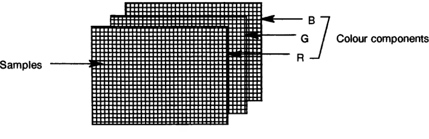
In the JPEG algorithm a source image consists of three colour components as shown in figure 1. Each pixel of a colour component is called as a sample of the image. A block of
8X8
samples is called one data unit A sequence of (3
to10)
data units is known as one Minimum Coded Unit (MCU).Samples
AG
J
Colour componentsFigure 1: Source image
OCT-based method in JPEG standard involves Discrete Cosine Transform, quantisation and encoding of an incoming image. The input image is divided into groups of rows. Each row group is converted into a standard format and divided into a number of Minimum Coded Units. DCT, quantisation and encoding is performed on each data unit. After encoding input image is transferred into an output JPEG file.
Logical steps needed in lossy compression are given below.
1. Input image is divided into small groups and the division is performed row by row.
2. Each image group is converted into a standard internal format
3. Colour space conversion is performed, e.g. RGB to YCbCr. This is a null step for grayscale images.
4. If required, an image group is expanded vertically and I or horizontally to fit a multiple of MCUs.
5.
Sub-sampling is performed on each image component, this leads to reduction of number of samples in some colour components. This step operates independently on each colour component. Sub-sampling of each sample is performed by taking average with respect to neighbouring sampes.6. Minimum Coded Units (MCU) are created by combining the required number of data units.
7. DCT, quantisation and Huffman encoding is performed on each data unit
3.
Implementation of the JPEG algorithm on a transputer based system
Most of the current software implementation of the JPEG algorithm are in sequential form.
In
a~mpting to perform JPEG data compression in real-time, parallel processing algorithms are being
tn~ on a transputer network. Array topology has been selected for this study. JPEG algorithm will
be unplemented on transputers in MIMD mode using Helios C in conjunction with the Component Distrib!-lted Language (CDL), working under the Helios operating system. POSICs ( Portable Operating System Instruction Codes ) library has been selected for communication between transputers.
A few important terms which will be used later, are defined below.
1. Link usage: 2. Bottleneck:
3. Mean inter-processor
distance: 4. Scalability:
5. Speedup (S):
6. Efficiency (E):
3.1 Helios operating system
Maximum number of the available links used in a network.
A link in the topology which carries a large volume of data traffic. The average number of hops required to communicate between pairs of processors in the network.
A measure of topology performance as the number of processing elements is varied.
A measure of increased processing speed on a parallel processor.
Time taken by a task on a single processor Tserial
SN = --- =
---Time taken by a task on N processors T parallel
When a task is divided into sub-tasks which need to communicate with each others, then the overall speedup is a function of the relative times spent on computing and communicating.
A measure of how much each processor contributes to the speedup of the parallel system.
~ = S I N Where S is the speedup, N is number of processors.
Helios is a distributed operating system developed by Perihelion Software Limited. Helios is intended to run on a wide range of system configurations. A typical hardware configuration consists from two to twenty processors in a tightly bound cluster. This could be either a purpose built system or an upgraded workstation. Helios is capable of expanding into the available processors and of sharing the workload amongst them. Such clusters may themselves be interconnected in a local area network to allow the sharing of data and expensive devices such as high capacity discs and laser printers [2].
Helios provides four levels of communication between processors. The lowest level is used in the nucleus: PutMsg() and GetMsgO are the message passing primitives that provide the basis of all Helios communication. The level above this is provided by system library functions Read() and Write(). These calls operate on streams and have timeouts associated with each requested transaction. At the next level are the POSICs readO and write() functions. Calls to the POSICs functions are based on POSICs file descriptors. The highest level of communication is at the language level, which depends upon the programming language used.
We have chosen POSICs level of communication to implement JPEG algorithm on transputer network on the basis of the following factors.
1. This communication mechanisms ensures some degree of reliability and fault tolerant i.e.
it provides error detection and recovery from failure and there is a guarantee that messages will arrive at their respective destinations.
2. It offers greater functionality than lower level libraries.
3. Most importantly, POSICs library can also be used on other parallel architecture, thereby
In POSICs based communication inter-processor message transmission times over transputer links are characterised by a relationship of the form [2]:
where
1total
=
toverhead + tinit + N.ttx=
1461.42 + N X 0.567 micro sec --- {1} 1total=
message transmission timetoverhead
=
loop overhead on each test iteration~nit
=
message initialisation time N=
number of bytes in a message 1tx = transmission time for one byteComponent Distribution Language (CDL) is the language which facilitates parallel programming under Helios. The purpose of CDL is to provide a high-level approach to parallel programming.
3.2 Implementation of JPEG algorithm on a transputer network
For implementing the JPEG algorithm array topology has been selected on the basis of the following factors.
1 . Link usage: All four links of the transputer can be used, including the end links in a torus topology.
2. Bottleneck: Bottlenecks can be minimised by using as many links as possible for distributing the data over the network
3. Mean inter-processor distance: This distance is less in the array topology than in many other one or two dimensional topologies.
Implementation of the JPEG algorithm is being tested on different size networks, to determine scalability of the array topology for this problem. The data used to determine scalability is subject to the following factors:
1. Programming under the Helios operating system.
2. Communication is performed by using the POSICs routines.
3. A 125 X 125 Portable Pixel Map (PPM) P6 format input image is used. This format consists of three image components: RGB.
Therefore, the number of samples is
=
125 X 125 X 33.2.a Implementation of JPEG algorithm on a three processors network
The task graphs of the JPEG algorithm for parallel implementation look like a regular tree structures. Tree structures can be embedded in array structures quite easily. The next important question is how many processors can be used effectively? The minimax problem of parallel computing states that if we execute a job on only one machine then there is no communication overhead; at the same time we cannot exploit parallel operations. On the other hand, if we distribute the problem on too many processors the communication overhead can nullify the advantage of parallel processing.
Our aim is to determine the suitability of different sire array topology networks for the JPEG algorithm. We will first describe a parallel implementation of the JPEG algorithm on a Transputer network with three processors, followed by an implementation on seventeen processors. Speedup (S) and efficiency (E) will be used as the main parameters to characterise the effectiveness of these networks.
Processor-A
Main processor Processor-M
Processor-B
Figure 2: Tree topology for a network of three transputers
Processor-B
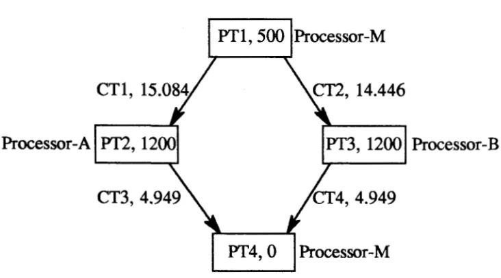
Figure 3: Task graph for three processors
Functions performed by the processing and communication tasks are as follows:
Task number Function
PTl Main processor performs initial set up of input image and divides input image into
two parts.
CTI First part of the image, which consists of 125 X 64 X 3 samples, is transferred from
Processor-M to Processor-A.
Communication time for transferring 125 X 64 X 3 samples (from equation {1}).
= 1461.421142 X 10-3 + 0.567642 X ( 125 X 64 X 3) X 10-3 =15.084 msec.
CT2 Remaining samples ( 125 X 61X3) are transferred from M to
Processor-B in 14.446 msec.
PT2 &3 On processors A and B, JPEG algorithm steps 2 to 7 are performed (see section 2), on each part of the image.
Execution time on Processors A and B for performing PT2 and Pf3 =1200 msec. This value has been obtained by executing the tasks on a single transputer and recording the time with the help of the system clock
CT3&4 After performing each task, encoded image is transferred back to the main processor. For optimum quality the encoded image consists of four times less samples than in the source image. Thus, encoded image comprises
..
The communication time for transferring encoded image from Processors A and B to the Processor-M
=
4.949 msec. This value has been obtained from the equation { 1}.PT4 Main processor collects encoded image from Processors A and B transfers it into an output JPEG file with header/marker. Encoded samples are directly stored in the JPEG output file on the main processor. Thus, execution time for task 4 is considered
to be zero.
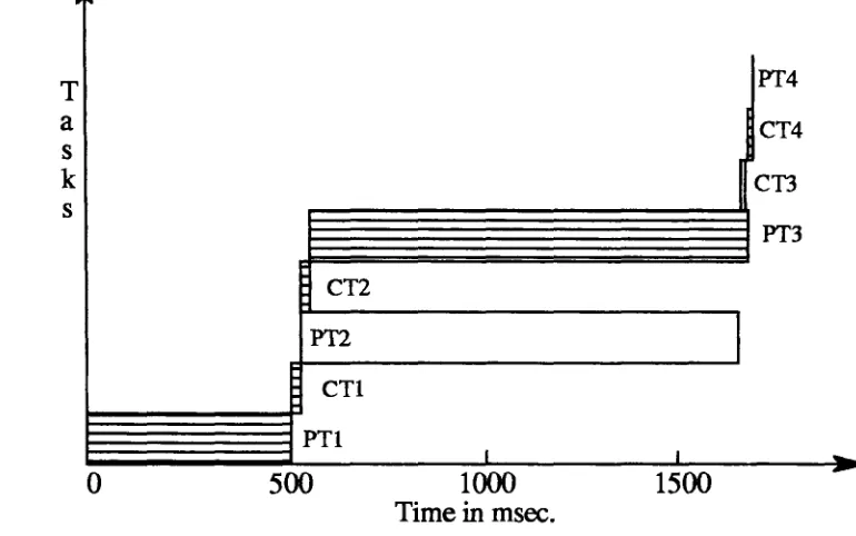
The execution schedule of JPEG algorithm on a three processors is shown in the
form
of Gantt chart in figure 4. A Gantt chart [3] essentially shows the scheduling of various tasks on the time axis.T
a
s k s
0
PT4
CT4
(en
~~~~~~~PT3
CT2
PT2
CTl
PTl
500
I
I I
1000 1500
Time in msec.
Figure 4: Gantt chart for a three processor network
From the Gantt chart of figure 4 we can clearly see the tasks that contribute to the total execution time. These tasks are shown with hash lines inside the bars representing the tasks. Other tasks overlap in execution and therefore do not contribute to this calculation.
Total time taken by three processors
=
t(Pfl) + t(CTl) + t(CT2) + t(Pf3) + t(CT4)=
500 + 15.084 + 14.446 + 1200 + 4.949 + 0=
1734.929 msec.Time taken on a single processor
=
500 + 1200 + 1200 + 0=
2900 msec.Speed up of parallel processor S3
=
2900/ 1734.929=
1.673.3b
Implementation of JPEG algorithm on seventeen transputers
The three transputer network is the smallest that can be utiliz.ed meaningfully. A seventeen transputer network is the largest available to us. In this section we consider mapping of the JPEG algorithm on a network of seventeen transputers.
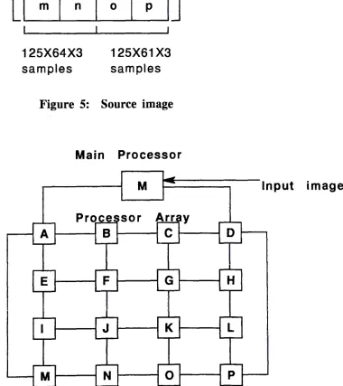
To map the JPEG algorithm on this network the source image can be split into sixteen parts as shown in figure
5.
The sixteen image parts are labelled as a, b, .~ , p. Each part of the source image can be processed on a transputer. This can be mapped quite elegantly onto a 4X4 array of transputers as shown in figure 6.125
x
125x
3 isamples
125 X 125 X 3 samples
I
a
be
fi j
m
n
125X64X3 samples
c
d
g
hk I
0 p
125X61X3 samples
Figure 5: Source image
64 X 125 X 3 samples
61 X 125 X 3 samples
Main Processor
M
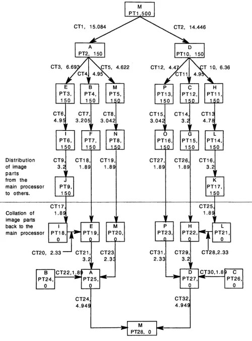
Input imageTasks required for executing the JPEG algorithm on a seventeen transputer network are listed below. The task graph of figure 7 shows the relationship between these tasks and the paths used for first distributing the uncompressed image on the network, and then for collecting the compressed image
parts. Y'!e ~se the notation described in section 3.2 for task identification and specification of the
execut10n tJ.mes.
Task number Function
PTl Input image is divided vertically into two parts, and other initialization functions such
as setting up the coding tables are performed on the main processor. t(PTl)
=
500CTl,2 The two image halves are transferred to processors A and D respectively.
CT3
CT4
CT5
Part
a
of the image is retained on Processor-A and the remaining image parts ofthe half image now on Processor-A are transferred to other processors as per the task
graph of figure 7. t(CTl)
=
15.084 and t(CT2)=
14.446Image parts
e,
i and j are transferred from A toE.
Image parts b and f are transferred from A to B.
Image parts
m
andn
are transferred from A to M.t(CT3) = 6.693
t(CT4)
=
4.95t(CT5) = 4.622
PT2 At this stage Processor-A becomes free to start processing its image part
a.
CT6
CT7
CT8
CT9
CTlO
CTll
CT12
CT13
CT14
CT15
CT16
Image parts i and j are transferred from E to I.
Image part f is transferred from B to F.
Image part n is transferred from M to N.
Image part j is transferred from I to J.
Image parts h, I and k are transferred from D to H.
Image parts c and g are transferred from D to C.
Image parts p and o are transferred from D to P.
Image parts I and k are transferred from H to L.
Image part g is transferred from C to G.
Image part o is transferred from P to
0.
Image part k is transferred from L to K.
t(CT6) = 4.95
t(CT7) = 3.205
t(CT8) = 3.042
t(CT9)
=
3.2t(CTlO)
=
6.36t(CTl l)
=
4.95t(CT12)
=
4.47t(CT13)
=
4.78t(CT14)
=
3.2t(CT15)
=
3.042t(CT16)
=
3.205PT2 to Each processor performs compression on its image part.
Pf 17 This takes 150 msec. i.e. for n
=
2 to 17 t(PTn)=
150CTI 7 to Encoded image parts are transferred back to the main processor as shown in
CT32 the task graph of figure 7. The time taken for each communication task is shown on
the arc representing the same.
PTl 8 to The main function of these tasks is to collect the encoded image parts.
Distribution of image parts from the
main processor
to others.
Collation of image parts back to the main processor
CT1, 15.084
PT2~
150I
M PT1 ,500
CT2, 14.446
I
PT1o~
150CT3,
~.69 ~4.622
CT4
,,
5CT12,
4
.
4/~T
10, 6.36/CT11~~
4 . 9 ,E B M
PT3, 150 CT6 4.9~ 'f I PT6, 150 PT4, 150 CT?, 3.205
,,
F PT?,
150
CT9, CT18, 3.2 1.89
1 ,
J PT9,
1 50
CT17 1.89
1 • 1 ,
I E
PT18, .... ~ PT19,
Q 1' I
CT8, 3.042
1 •
N PT8,
1 n
CT19, 1.89
I f
M PT20,
P C H
PT13, 150 CT15, 3.042 1 • 0 PT16,
1 .n
CT27, 1.89
I I p PT23,
I
PT12,
1 0
CT14,
3.2
I f G PT15, 150 CT26, 1.89 I f PT11, 1 "n
CT1 ~
4. 7E
111
L PT14,
150
CT16, 3.2 I I
K PT17,
150
CT25 1.BE I ,
H L
PT22.~ - PT21,
I I~ 0
CT20, 2.33 - CT21, CT23 CT31,
2.33
CT29, CT28,2.33 3.2
,,
2.3:B CT22,1..:8D A _
PT24, - PT25,~---...1
0 0
CT24, 4.949
3.2
I~
D CJ30, 1.8b C
PT27, - PT26,
0 0
CT32 4.94E
L---~ _I M ...--:....----J
-1
PT28, 0I
Task Name Time Processor Time Bar
en tS.0811; ~ ; I I
I I
en 6.7b
i
-I
CT6 4.9511 I
•
i
ICT9 I 3.2b[
•
I
ICT4 ! 4.9Sbi
•
I I !CT7 I I
I
3.2hi
•
ers 4.6111
•
•
I
Icrs 3.0Sh I I i
:
•
ICTl 14.4Sb /
I
I
i
i~1
I
crto 6.3Sb ~
I
I4.77b i
I
I
CT13 ~ I
I
CT16 3.2b!
I
E!II
I
i
I
I
CTll 4.95h i
•
ICT14 3.lbj
I
•
I
I
CT12 4.47b !
•
ens 3.03b i
I
•
I
I
I
I
I
PT2 lSOb ! A I I
I I I I I I I
PT3 lSOb E
PT4 lSOb
I I I I I I I
B
PTS lSOb IM
I
I I I I I
PT6 lSOhil I I I !
I I
PT7 lSOb 1 F I I I
I I I I
PT8 lSOb
I
I I I ! I I
N
I I ! I I
PT9 150b J
I I i I I I
PTlO 150h D
I I I I I I
PTll 15011 H
I I I I ' I
PTll 150h c
i I I ! I
PT13 15011 p
I I I I i i
PT14 15011 L
PT15
I I I I : I
I
150b I G
1SOllJO
I
I I ! ' I !
PT16
I ' I
PT17 150b (K
PT18 Oh I I @
I
PT19 011!E
I
@PTlO Ob M Ii)
PTll Ob IL
@
PTll ObJH
@
PTl3 Obi P @
PT14 Ob 1B I I
I
<il I
PT25 Ob;A <ill
i
I
@l
PT26 ObiC I
PT27 Ob\D
I
: !
PT28 Ob iMAIN <il
CT17 l.88h i I
CT18 l.88b j I
CT19 I 1.88h: I
cno 3.2bi
•
CT21 I 2.3211:
:
I
i
CT22
i
l.88h: ;;
I
' ! I !
CT23 I 2.32b: ; ; I ·
CT24 i 4.95b i i
•
CT25 I 1.8811
'1
!I!
I i
-
-1.88h !
Cfl6 ! i I
CT27 i us111
I
I I
3.2h
i
I:
\m
ens
I
ICT29 I 3.lb ( I
•
i
ICT30 ; 1.8811: I
•
1
I-·
2.32)11
I
I
CT31 I i I
•
,
!
- -
-4.9Sh '. ~
:
i•
CT32 I
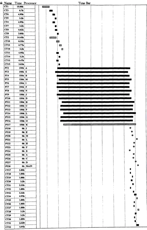
The Gantt chart of figure 8 was drawn by using Microsoft Project - a project management software.
The first column lists the task name. The second column contains the execution time. The units shown as 'h' stands for hours. Microsoft project does not allow smaller time units to be specified as fractions (for obvious reasons). We have entered data by equating one hour to one msec. The tasks on the critical path, i.e. those which contribute to the total execution time are filled with hatch lines. To improve the resolution of the Gantt chart, PTl which takes 500 msec'on the main processor, has been omitted from figure 8.
Time taken on a single processor
=
500 + 150 X 16= 2900
msecFrom Gantt the total time on the seventeen transputer network
=
500 + 198.93=
699 msecSpeed up of the seventeen processor network =
29001699
=
4.15Efficiency of the seventeen processor network
= 4.15 / 17
=
0.2444.
Conclusion
To reduce the number of bits used to store and transmit images, compression techniques are often used. JPEG is an international organisation which has developed a standard for digital image compression.
JPEG algorithm can be implemented on a network of processors connected in an array topology. With a network of three transputers a speedup of 1.67 can be obtained. This gives an efficiency of 55.73 for each processor. On a network of seventeen processors, with sixteen processors connected as a 4X4 array, a speedup of 4.15 can be obtained. The average efficiency of each processor is only 24·L\
%.
Thus, as we go from a singe processor to three processors, and then to a seventeen processor network, we can reduce the total time to solution, but the level of processorutilisation also falls. ·
BIBLIOGRAPHY
[l]
[2]
[3]
Gregory K. Wallace," The JPEG Still Picture Compression Standard." IEEE Transaction on Consumer Electronics, Vol. 38, No. 1, Feb. 1992, pp. xviii-xxxiv.
Davis Ian, Perihelion Software Limited, ''Helios operating system", 1992.
Ted G. Lewis and Hesham El-Rewini, "Introduction to Parallel Computing", Prentice Hall,