Electronic Thesis and Dissertation Repository
5-29-2017 12:00 AM
Study on the mechanical behavior of directly compounded long
Study on the mechanical behavior of directly compounded long
glass fiber reinforced polyamide 6 composites
glass fiber reinforced polyamide 6 composites
Yuchao Liu
The University of Western Ontario
Supervisor Jeffrey T. Wood
The University of Western Ontario
Graduate Program in Mechanical and Materials Engineering
A thesis submitted in partial fulfillment of the requirements for the degree in Master of Engineering Science
© Yuchao Liu 2017
Follow this and additional works at: https://ir.lib.uwo.ca/etd
Part of the Mechanics of Materials Commons
Recommended Citation Recommended Citation
Liu, Yuchao, "Study on the mechanical behavior of directly compounded long glass fiber reinforced polyamide 6 composites" (2017). Electronic Thesis and Dissertation Repository. 4576.
https://ir.lib.uwo.ca/etd/4576
This Dissertation/Thesis is brought to you for free and open access by Scholarship@Western. It has been accepted for inclusion in Electronic Thesis and Dissertation Repository by an authorized administrator of
iii
With great lightweight potential, high performance-to-cost ratio and mass productivity,
direct-compounded long fiber thermoplastics (D-LFT) have drawn great attention from
the automotive industry. With better mechanical properties and higher service
temperature, polyamide 6 (PA6) was used to replace polypropylene (PP) which is almost
the exclusively used matrix for the D-LFT process currently. The investigation was
performed on this new material with a focus on the effect of fiber content, processing
parameters, temperature and tailored reinforcement on mechanical behavior. The results
show that the mechanical properties of this new material are sensitive to the variation of
fiber content and service temperature but insensitive to the varied processing parameters.
Tailored reinforcement technique is a feasible and predictable approach to adjust the
mechanical properties of this new material.
Keywords
D-LFT, glass fiber, thermoplastic, polyamide 6, mechanical property, fiber content,
iv
Firstly, I would like to thank Dr. Jeff Wood for giving me the opportunity to enter this
amazing composite world. During the past two years, it was your gentle guidance and
positive encouragement that helped me to step forward. I had not anticipated to be able to
take so many valuable scientific events such as the internship in Fraunhofer Project
Center of Composite Research (FPC@Western) in my first term, the summer school in
Germany and ACCE conference in the US. I was so lucky to have someone like you as
my supervisor.
I also would like to say thanks to Dr. Ying Fan. I appreciate that you put me on your back
to adapt to this new environment. Thank you for providing me the suggestions almost in
every aspect of my life here. To be honest, as sometimes being a little frivolous on my
research work, I appreciate that you can always bring me back on the right way. I just
feel lucky here to have someone like you who supervises me so carefully.
Then I would like to thank all the staffs from the FPC@Western, including Vanja
Ugresic, Marcel Holzner, Louis Kaptur and Rob Cosh for your kind help with the
preparation of this project as well as my internship there. Thank all the industrial partners
including General Motors, BASF, Johns Manville, Dieffenbacher, Elringklinger, NSERC
for offering the valuable financial and technical supports.
Additionally, I would like to say thanks to my previous supervisors, Hongwei Li and
Dunbo Yu. Without your kind support, I might not be able to come to Canada to pursue
my goals.
At last, I want to say thanks to my families. You are all the reasons I step forward. Thank
my wife, Fei, for giving me all her love and making me be the luckiest man in the world.
Thank my parents for understanding and supporting me to extend my career in Canada. I
v
Abstract ... iii
Acknowledgments... iv
Table of Contents ... v
List of Tables ... viii
List of Figures ... ix
Chapter 1 ... 1
1 Introduction ... 1
Motivation ... 1
Task description ... 2
Chapter 2 ... 4
2 Literature review ... 4
Fiber reinforced plastics ... 4
2.1.1 Matrix materials ... 4
2.1.2 Fiber products ... 8
Long fiber reinforced thermoplastics ... 13
2.2.1 Processing techniques for long fiber reinforced thermoplastics ... 13
2.2.2 Influence of fiber content on the mechanical properties of LFT composites... 16
2.2.3 Influence of processing parameters on the mechanical properties of LFT composites ... 18
2.2.4 Environmental effect on the mechanical properties of LFT composites .. 22
2.2.5 UD tape reinforcement on D-LFT composite ... 24
Prediction of mechanical properties of long fiber thermoplastic ... 26
vi
Materials ... 31
Preparation ... 31
3.2.1 Dieffenbacher D-LFT-ILC line... 31
3.2.2 D-LFTs with different fiber contents ... 33
3.2.3 D-LFTs with different processing parameters ... 39
3.2.4 Reinforcing D-LFT with UD tapes ... 40
Methodology ... 43
3.3.1 Mechanical testing ... 43
3.3.2 Characterization of microstructure ... 48
3.3.3 Measurement of fiber volume fraction ... 49
3.3.4 Measurement of fiber length distribution ... 49
3.3.5 Measurement of fiber orientation distribution ... 49
Chapter 4 ... 52
4 Result and discussion ... 52
Mechanical behavior of D-LFTs with different fiber contents ... 52
4.1.1 Spatial variations of thickness and fiber content within individual plaque ... 52
4.1.2 Mechanical testing results ... 54
4.1.3 Prediction of Young’s modulus of D-LFT... 61
4.1.4 Effect of fiber content on fiber length distribution and fiber orientation distribution ... 66
Effect of the processing parameters on the mechanical properties of glass fiber/PA6 D-LFTs ... 68
vii
Mechanical behavior of glass fiber/PA6 D-LFT at different temperatures ... 74
4.3.1 Tested mechanical properties ... 74
4.3.2 Analysis of failure mode ... 77
Characterization of the mechanical behavior of UD tape reinforced D-LFT with different stacking sequence ... 80
4.4.1 Tested mechanical properties ... 82
4.4.2 Prediction of in-plane elastic properties ... 88
4.4.3 Microstructure ... 91
Chapter 5 ... 94
5 Conclusion ... 94
Summary ... 94
Future work ... 95
6 References ... 96
viii
Table 2-1 Properties of some commonly used resins. [1] ... 5
Table 2-2 Repeating units of different polyamides... 7
Table 3-1 Properties of PA6 (Ultramid 8802HS) and glass fiber (JM 886) used in this
work. ... 32
Table 3-2 List of the processing parameters in 8 conditions, room temperature (R.T.) is
ix
Figure 2-1 Schematic molecular structure of a) semi-crystalline thermoplastics
(highlighted in red) and b) amorphous thermoplastics ... 6
Figure 2-2 Repeating unit of polypropylene. ... 7
Figure 2-3 The molecular structure of glass fiber. ... 9
Figure 2-4 The layered structure of carbon fiber. [8] ... 9
Figure 2-5 Shear lag model showing: a) unstressed system, b) axial displacements u introduced on applying tension parallel to the fiber and c) variation with radial location of the shear stress 𝝉 and strain in the matrix. [1] ... 10
Figure 2-6 Distribution of a) tensile stress in the fiber and b) interfacial shear stress along the interface for different fiber length. [1] ... 12
Figure 2-7 Relationship between fiber length and different mechanical properties (stiffness, strength and toughness) of PP based composites. [11] ... 12
Figure 2-8 Schematic of the GMT processing technique. ... 14
Figure 2-9 Schematic of the LFT-G processing technique. ... 14
Figure 2-10 Parameters involved in screw design: barrel diameter Db, centerline distance A, clearance screw-barrel Cb, clearance screw- screw Cs and flight pitch P. ... 20
Figure 2-11 Four types of twin-screw designs with different placements of high mixing elements resulting in different shear flow. [44] ... 20
Figure 2-12 Local cracks caused by moisture absorbed in composites. [60] ... 23
Figure 2-13 Comparison between the FRPs based on different fiber products. [100] ... 25
x
line... 35
Figure 3-3 The first extruder (ZSE) of Dieffenbacher D-LFT-ILC line. ... 35
Figure 3-4 Fiber feeding system of Dieffenbacher D-LFT-ILC line with a) continuous
glass fiber tows b) plastic tube system c) iron bars for fiber preheating d) roving
separation apparatus above the second extruder. ... 36
Figure 3-5 The second extruder (ZSG) of Dieffenbacher D-LFT-ILC line. ... 37
Figure 3-6 Schematic of the second extruder (ZSG) of Dieffenbacher D-LFT-ILC line. 37
Figure 3-7 Conveyor (PAZ) of Dieffenbacher D-LFT-ILC line with a) composites charge
and b) the conveyor. ... 38
Figure 3-8 Dieffenbacher DCP-U 2500/2200 hydraulic press and b) the compression mold used in this work. ... 38
Figure 3-9 Size and charge position of the plaques prepared in this work. ... 39
Figure 3-10 Unidirectional continuous fiber tape with 60 wt.% fiber provided by BASF.
... 41
Figure 3-11 Fiberforge Relay@ 1000 at FPC@Western. ... 42
Figure 3-12 Layups with stacking sequence of [0/90]s a) before consolidation and b)after
consolidation. ... 42
Figure 3-13 Detailed structure of the layups and co-molded products with three types of
stacking sequence... 43
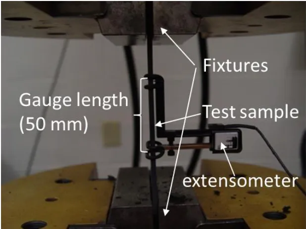
Figure 3-14 Setup of the tensile test with a 50mm extensometer. ... 46
xi
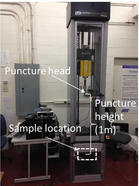
Figure 3-18 Dynatup Instron 9250 HV drop tower. ... 48
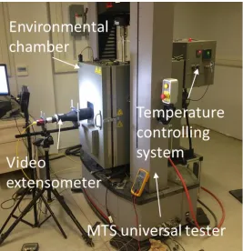
Figure 3-19 MTS load frame equipped with an environmental chamber and a video extensometer. ... 50
Figure 3-20 a) Hitachi S-4500 field emission SEM and b) Nikon Eclipse L150 microscope. ... 50
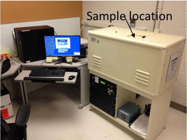
Figure 3-21 GE eXplore SP "MS" micro-CT. ... 51
Figure 4-1 Fiber thickness distribution within a D-LFT plaque with 30 wt.% fiber. ... 53
Figure 4-2 Fiber content distribution within a D-LFT plaque with 30 wt.% fiber. ... 54
Figure 4-3 Tensile and flexural modulus in both flow and cross-flow directions of glass fiber/PA6 D-LFTs with different fiber contents. ... 55
Figure 4-4 Tensile and flexural strength in both flow and cross-flow directions of glass fiber/PA6 D-LFTs with different fiber contents. ... 55
Figure 4-5 Fracture surfaces of tensile specimens tested in 0 and 90-directions of D-LFT with a) 30 wt.% fiber and b) 50 wt.% fiber. ... 57
Figure 4-6 SEM images of the fracture surfaces of tensile D-LFT sample with a) 20 wt.% fiber tested in direction and b) tensile D-LFT sample with 50 wt.% fiber tested in 0-direction. ... 57
Figure 4-7 SEM image of the fracture surface of a tensile D-LFT specimen with 50 wt.% fiber tested in 90-direction. ... 58
xii
Figure 4-10 Poisson’s ratio in both flow and cross-flow directions of glass fiber/PA6
D-LFTs with different fiber contents. ... 59
Figure 4-11 Thickness specific impact peak force, impact energy and energy to peak
force of D-LFTs with different fiber contents. ... 60
Figure 4-12 Failed impact D-LFT specimens with fiber contents of a) 30-60 wt.% and b)
20 wt.%. ... 61
Figure 4-13 a) Position and b) size of the sample cut for micro-CT scan. ... 62
Figure 4-14 Images of cross sections through the thickness of a D-LFT sample by
micro-CT scan with resolution of 6 micrometers. ... 62
Figure 4-15 Fiber orientation distribution (FOD) measured on 9 layers of a D-LFT
sample as shown in Figure 4-14... 64
Figure 4-16 Measured fiber length distribution (FLD) of D-LFT with 30 wt.% fiber. .... 65
Figure 4-17 Young’s moduli in 0 and 90-directions of D-LFT with 30 wt.% fiber
predicted by MROM and Halpin-Tsai models and determined by tensile tests. ... 65
Figure 4-18 Relationship between value of k1k2 and different fiber content which is
measured with tested E11, known material properties and fiber volume fraction through
MROM model. ... 67
Figure 4-19 Fiber length factor k1 calculated with different fiber length based on shear lag
model... 67
Figure 4-20 Tensile modulus and strength in both 0-direction and 90-direction of glass
fiber/PA6 D-LFTs specimens prepared in different processing parameters (T1: standard
condition; T2&T3: lower and higher screw speed; T4&T5: higher and lower filling level;
xiii
standard condition; T2&T3: lower and higher screw speed; T4&T5: higher and lower
filling level; T6&T7: lower and higher melt temperature; T8: fiber preheating). ... 70
Figure 4-22 Unnotched impact properties in both 0-direction and 90-direction of
D-LFTs prepared in different processing parameters (T1: standard condition; T2&T3: lower
and higher screw speed; T4&T5: higher and lower filling level; T6&T7: lower and higher
melt temperature; T8: fiber preheating). ... 71
Figure 4-23 Length weighted and numerical average fiber length measured on T4 (the highest filling level) and T5 (the lowest filling level) plaques. ... 71
Figure 4-24 Fiber length factor k1 calculated with different average fiber length based on
shear lag model. ... 73
Figure 4-25 Fiber contents measured on D-LFTs prepared in different conditions (T1:
standard condition; T2&T3: lower and higher screw speed; T4&T5: higher and lower
filling level; T6&T7: lower and higher melt temperature; T8: fiber preheating). ... 73
Figure 4-26 Fiber content measured on both the 2nd and the 9th out of 10 D-LFT plaques
for T1, T4 and T5. ... 74
Figure 4-27 Tensile and flexural stress-strain curves at -40C, R.T., 85C and 120C for
the D-LFTs with fiber contents of 20, 30 and 40 wt.%. ... 75
Figure 4-28 Tensile and flexural moduli tested at -40C, R.T., 85C and 120C of
D-LFTs with fiber contents of 20, 30 and 40 wt.%. ... 76
Figure 4-29 Tensile and flexural strengths tested at -40C, R.T., 85C and 120C of
D-LFTs with fiber contents of 20, 30 and 40 wt.%. ... 76
Figure 4-30 Tensile and flexural strain at failure tested at -40C, R.T., 85C and 120C of
xiv
Figure 4-32 SEM images of fracture surfaces of tensile D-LFT specimens with 20 wt.%
fiber tested at -40C. ... 79
Figure 4-33 SEM images of fracture surfaces of tensile D-LFT specimens with 20 wt.%
fiber tested at R.T. ... 79
Figure 4-34 SEM images of fracture surface of tensile D-LFT specimens with 20 wt.% fiber tested at 85°C. ... 79
Figure 4-35 SEM images of fracture surface of tensile D-LFT specimens with 20 wt.%
fiber tested at 120°C. ... 81
Figure 4-36 SEM images of fracture surfaces of tensile D-LFT specimens with 20 wt.%
fiber tested a: -40°C, b: R.T., c: 85°C and d: 120°C. ... 81
Figure 4-37 SEM images of fracture surface of tensile D-LFT specimens with 40 wt.%
fiber tested at R.T. ... 82
Figure 4-38 Thickness specific impact energy and thickness specific peak load tested on
pure D-LFT with 30 wt.% fiber, layups and comouldings with 3 types of stacking
sequence ([0]s, [0/90]s and [0/90/+45/-45]s). ... 83
Figure 4-39 Failed puncture specimens: a) D-LFT, b) #1L, c) #2L, d) #3L, e) #1C, f) #2C
and g) #3C. ... 84
Figure 4-40 Tensile stress-strain curves in 0 and 90-directions for a) D-LFT and layups
with 3 stacking sequences and b) comoldings with 3 stacking sequences. ... 85
Figure 4-41 Tensile moduli and strengths in 0 and 90-directions for a) D-LFT and
xv
tested in 90°-direction. ... 86
Figure 4-43 Flexural stress-strain curves in both 0 and 90-directions for a) D-LFT and
layups with 3 types of stacking sequence and b) comoldings with 3 types of stacking
sequence. ... 87
Figure 4-44 Flexural modulus and strength in 0-direction and 90-direction for pure
D-LFT with 30 wt.% fiber, layups with 3 types of stacking sequence and comoldings with 3
types of stacking sequence. ... 87
Figure 4-45 Failed flexural specimens tested in 0°-direction of layups and comouldings
with three types of stacking sequence: a) #1L tested in 90°-direction viewed from bottom
and side, b) #2L tested in 90°-direction viewed from bottom and side, c) #3L tested in
90°-direction viewed from bottom and side, d) #1C tested in 0° and 90°-direction, e) #2C
tested in 0° and 90°-direction and f) #3C tested in 0° and 90°-direction. ... 88
Figure 4-46 Shear modulus in both 0 and 90-directions for pure D-LFT with 30 wt.%
fiber, layups with 3 types of stacking sequence and comoldings with 3 types of stacking
sequence. ... 89
Figure 4-47 Comparison between predicted and experimental elastic properties of layups
and relevant comoldings with different stacking sequence. ... 92
Figure 4-48 Micrographs of a) top portion and b) bottom portion of the cross section of a
Chapter 1
1
Introduction
Direct-compounded long fiber reinforced thermoplastics (D-LFT) are gaining an
increasing market share in the automotive industry due to mass productivity and high
performance-to-cost ratio. With better mechanical properties and higher service
temperature, polyamide (PA6) was selected as the matrix material to replace the most
commonly used thermoplastic matrix, polypropylene (PP). As the material system of
glass fiber/PA6 used in the D-LFT process has never be reported before, a fundamental
investigation was performed on this new material. The aims of this work were to:
i. build the material card and determine the proper elastic model of this material for the subsequent finite element (FE) simulation,
ii. evaluate the effect of fiber content, processing parameters and temperature on the mechanical properties of this material,
iii. determine the proper approach to apply a tailored reinforcement to this material.
Motivation
The main motivation for this work comes from the great lightweight potential of fiber
reinforced polymers (FRPs). Increasing environmental awareness and stricter emission
standards around the world give a huge drive to the development of environmentally
friendly techniques, among which electric vehicles (EVs) can be the most attractive. One
of the main issues that drag the wheels of an EV is the heavy battery, which limits the
mileage to 300 km per charge. Replacing the traditional metallic semi-structural
components with FRP based ones is considered as a good way to reduce the weight.
The second motivation is the mass productivity and relatively high performance-to-cost
ratio of the D-LFT process. Of great importance to the automotive industry, the mass
productivity of D-LFT is derived from the short cycle time of the thermoplastic matrix.
Due to the long curing procedure, the cycle time for thermoset based FRPs is typically
more than 10 minutes which is much longer than around 30 second for thermoplastic
semi-finished products. The continuous fibers are directly incorporated with the melt to
produce the final products in the D-LFT process, which significantly reduce the cost as
compared with glass mat thermoplastics (GMT) and long fiber thermoplastic granulates
(LFT-G).
The third motivation is to improve the mechanical properties and service temperature by
using PA6 as the matrix material. PPs have been the most commonly used matrix
material in the D-LFT process due to their compatibility with many processing
techniques, chemical resistance, and moisture & oxygen barrier. However, the relatively
low mechanical properties of PP make suppliers eager to replace them with PA6 which is
type of engineering polymer. The relatively high elevated-temperature mechanical
properties of PA6 may also be able to increase the service temperature of the composite
material. However, the concerns about using PA6 as the matrix are its high viscosity,
hydrophilicity, and oxidation-sensitivity.
Task description
As glass fiber/PA6 is a new material system for the D-LFT process, this work will
investigate the mechanical behavior of this new material with focus on the effect of some
fundamental factors. As an industry scaled composite processing line located at
Fraunhofer Project Center for Composite Research in Western University
(FPC@Western), the Dieffenbacher direct long fiber thermoplastic in-line compounding
(D-LFT-ILC) line will be employed to prepare the materials involved in this work.
As one of the most important factors for the FRPs, fiber content determines the
mechanical properties. The first task is to evaluate the effect of fiber content on both
mechanical properties and microstructure of this new material. The ladder of fiber
content is set to be 20, 30, 40, 50, 55 and 60 wt.%. Tensile, flexural, shear, impact tests
will be performed to quantify the effect of fiber content on the mechanical properties.
Observations of the fracture surface with a scanning electron microscope (SEM) will be
employed to evaluate the effect of fiber content on the microstructure. With the measured
properties of this new materials will be predicted based on existing models and compared
with the experimental result.
As glass fiber/PA6 is a new material system which has never been used in this
Dieffenbacher D-LFT-ILC line and the mechanical properties of FRPs are expected to be
very sensitive to the processing-dependent microstructure, the second task is to evaluate
the effect of the processing parameters on this new material. The focus of this work will
be placed on the compounding process parameters, which include screw speed, melt
temperature, filling level and fiber preheating.
Since the material will be used in an automotive structural application, it is of great
importance for the original equipment manufacturers (OEMs) to have an idea how this
material behaves at different temperature. The third task is to characterize the mechanical
behavior of this new materials at different service temperatures. Both tensile and flexural
tests will be performed in an environmental chamber to characterize the mechanical
properties. SEM will be used to observe the fracture surface to analyze the failure mode.
For some parts of the component that have higher mechanical requirements, the capacity
of locally adjusting the mechanical properties of this new material need to be achieved.
With this task, the unidirectional (UD) tapes, in which all the fibers are continuous and
aligned in the same direction, will be used to reinforce this new material. Different
stacking sequences will be used to reinforce the D-LFTs in different ways, which are
expected to broaden the range of mechanical properties of this material. The elastic
properties of the new hybrid materials will be predicted and compared with the
Chapter 2
2
Literature review
Fiber reinforced plastics
Owing to the great lightweight potential as semi-structural materials, fiber reinforced
polymers (FRPs) are gaining more and more attention from industry, especially from
automotive companies. FRPs consist of a polymer matrix and reinforcing fibers. The
mechanical performance of FRPs was proven to strongly depend on the properties of
matrix and fiber components as well as the interface quality [1, 2].
2.1.1
Matrix materials
The role of the matrix in FRPs is to transmit the external force to the fibers through the
interface shear stress, keeping the part in shape, bond the fibers together, compensate the
overloads and protect the fibers from environmental damage. The matrix-related
properties such as thermal, physical and chemical properties strongly depend on the
choice of matrix. Based on the matrix used, FRPs can be separated into thermosets based
FRPs and thermoplastic based FRPs. The properties of some commonly used matrix
polymers are listed in Table 2-1.
With the cross-linked 3-dimensional (3D) structure formed during the curing process,
thermoset based FRPs have many advantages including good mechanical properties, high
thermal resistance to creep, low pressure and temperature required for the molding, good
fiber impregnating quality and low cost. These make thermosets more competitive than
thermoplastics to be used as the matrix material of FRPs until now. But the further
growth of thermoset based FRPs is limited by long cycle time and limited shelf life [3].
Unlike thermosets, thermoplastics are not cross-linked, which can be categorized based
on the degree of crystallinity into two groups: amorphous thermoplastics and
Table 2-1 Properties of some commonly used resins. [1] Young’s modulus (GPa) Tensile strength
(MPa)
Max. strain (%) Max. operation temperature (°C)
Unsaturated polyester 3.5-4.7 50-70 2-5 100
Epoxy 2.8-3.7 70-90 2-10 200
Phenol 3.7-5.9 15-20 1-2 250
Polypropylene (PP) 1.0-2.0 25-40 100-600 80
Polyamide (PA) 3.0-3.2 80-90 70-300 100
Polyethylenimine
(PEI)
3.0-3.3 80-100 60-80 200
Polyether ether ketone
(PEEK)
3.6-3.8 100-120 80-100 250
entanglements between them and the high degree of molecular alignment. The reported
maximum degree of crystallinity of thermoplastics can go up to 85% [1].
Attributes including high impact resistance, short cycle time, unlimited shelf life and
recyclability have enabled thermoplastics to gain remarkable growth in recent years,
especially in the automotive industry. However, the issues related to fiber impregnation
due to high viscosity, the mechanical property degradation at elevated temperature and
the creep behavior are the main drawbacks of thermoplastics, which need to be overcome
in the future [4].
Polypropylenes (PPs), with the repeating units shown in Figure 2-2, are the most widely used thermoplastic matrix, due to the compatibility with many processing techniques, the
Figure 2-1 Schematic molecular structure of a) semi-crystalline thermoplastics (highlighted in red) and b) amorphous thermoplastics
semi-crystalline thermoplastic, PP can achieve a degree of crystallinity of 30-60%.
However, the low mechanical properties and the low service temperature of PPs limit the
growth of their application. The Young’s modulus and tensile strength of PPs are just half
of the typical engineering thermoplastics. With glass transition temperature (Tg) of
around 10°C, the mechanical properties of PP drop significantly when temperature rises
above 50°C.
Polyamides (PAs) are polymers which contain repeating amide groups (-CO-NH-).
Proteins are an example of polyamides in nature. Artificial polyamides can be divided
into two groups: aromatic polyamides and aliphatic polyamides. Benefiting from the
aromatic structure and the hydrogen bonds, the aromatic polyamides have such high
mechanical properties and good thermal properties that they were always used for
reinforcement, such as Kevlar©[6]. The aliphatic polyamides are very important
semi-crystalline engineering polymers. The high degree of crystallinity gives polyamide
excellent mechanical properties. Also attractive is their good resistance to many solvents.
However, the polar amide groups make PAs vulnerable in a humid environment because
the absorbed water can act as a plasticizer to degrade the mechanical properties of PAs.
Figure 2-2 Repeating unit of polypropylene.
The nomenclature of polyamides is based on the number of carbon atoms in the repeating
unit. Some examples are shown in Table 2-2. Among these, PA6 and PA6.6 are the most widely used. With different molecular structures, PA6.6 has better mechanical properties
and lower water absorption than PA6. But the differences are very limited [7].
Table 2-2 Repeating units of different polyamides.
Type of polyamide Repeating unit
Polyamide 6
Polyamide 6.6
Polyamide 6.10
Polyamide 11
2.1.2
Fiber products
The vast majority of fibers used in FRPs are glass and carbon. Glass fibers are the most
widely used reinforcement in industry. As shown in Figure 2-3, the primary constituent of glass fibers is silica (SiO2). Silicon, aluminum, boron and oxygen atoms form the 3D
cross-linked network with some modifiers of sodium and potassium. As the structure of
glass fiber is amorphous, the properties are isotropic. Glass fibers have many advantages,
such as high mechanical properties, good adhesion to the matrix, high service
temperature, low thermal expansion, low electrical conductivity and low price.
Carbon fibers consist of small crystallites of turbostratic graphite, as shown in Figure 2-4. Basically, carbon fibers have a two-dimensional (2D) layered structure, in which each layer is a covalently bonded graphite single atomic layer. The different layers are
connected by van der Waals forces. Carbon fibers are therefore highly anisotropic. With
outstanding specific mechanical properties, carbon fibers are usually employed in
high-performance applications. The main drawback of carbon fibers is the high price.
Based on the length of fiber products used, FRPs can also be classified into short fiber
reinforced polymers, long fiber reinforced polymers and continuous fiber reinforced
polymers. In the first two, the fibers are always discontinuous, but may have a random or
preferred orientation, whereas, in the latter case, the fibers typically extend the length of
the part and are aligned in the same direction.
Generally, the fiber length (aspect ratio) is of great importance to determine the
mechanical properties of FRPs. The shear lag model is applied here to clarify the
relationship between fiber length and mechanical properties [9]. When a composite is
subjected to an external force, the fiber and the matrix are subjected to different
elongations due to their different moduli. The external force is transmitted from the
matrix to the fiber through the interfacial shear stress. This concept is embodied by the
Figure 2-3 The molecular structure of glass fiber.
Figure 2-5 Shear lag model showing: a) unstressed system, b) axial displacements u introduced on applying tension parallel to the fiber and c) variation with radial location of
the shear stress 𝝉 and strain in the matrix. [1]
Under an external force that is parallel to the fiber length, the fiber tensile stress and the
interface shear stress along the fiber length can be expressed as follows:
𝜎𝑓 = 𝐸𝑓𝜀𝑔[1 − cosh ( 𝑛𝑥
𝑟) sech(𝑛𝑠)] (2-1)
𝜏𝑖 = 𝑛𝜀𝑔𝐸𝑓
2 sinh ( 𝑛𝑥
𝑟) sech(𝑛𝑠) (2-2)
𝑊𝑖𝑡ℎ 𝑛 = [ 2𝑬𝒎
𝑬𝒇(1+𝑣𝑚) ln(1 𝑉𝑓)
] (2-3)
Where 𝜎𝑓 is the fiber tensile stress, 𝜏𝑖 is the interface shear stress, 𝑥 is the distance from
the fiber mid-point, 𝑟 is the fiber diameter, 𝑠 is the fiber aspect ratio, 𝐸𝑓 is the Young’s
modulus of fiber, 𝐸𝑚 is the Young’s modulus of matrix, 𝑉𝑓 is the fiber volume fraction,
𝑣𝑚 is the Poisson’s ratio of matrix and 𝜀𝑔 is the global strain. Figure 2-6 shows the predicted distribution of tensile stress and interface shear stress by Equation 2-1 and
Equation 2-2 along the length of a glass fiber embedded in a polyester matrix. The tensile stress increases from 0 at the fiber end to a maximum at the midpoint while the
The longer fiber with an aspect ratio of 50 enables the tensile stress to build up until the
fiber and matrix have the same strain at the midpoint. For the short fiber with an aspect
ratio of 5, the fiber is too short for the tensile stress to build up to the ultimate strength.
That means the longer fibers enable the matrix to transfer more stress to the fibers.
Therefore, the mechanical properties of FRPs can benefit a lot from the longer fibers. To
fully utilize the potential of the fiber strength, the critical fiber length (𝑙𝑐) is required,
which is expressed as below:
𝑙𝑐 = 𝜎𝑢𝑓𝑑
2𝜏𝑢𝑖 (2-4)
Where 𝜎𝑢𝑓 is the ultimate fiber tensile strength (MPa), d is the fiber diameter (mm) and
𝜏𝑢𝑖 is the ultimate interfacial shear strength (MPa). Thomason [10] found that the effects
of fiber length and fiber diameter on impact properties are different. The fiber length is a
dominating factor in notched impact tests which is generally used to determine both the
impact energy and notch sensitivity while the fiber diameter has a more obvious effect in
unnotched impact tests which is usually used to evaluate the complete impact resistance.
Derived by Thomason et al. [11], the relationship between the fiber length and the
mechanical properties of FRPs is shown in Figure 2-7. Obviously, the fiber length needs to reach certain critical values to fully realize the mechanical potential of FRPs.
In addition, sizing is also very essential for the resulting strength since the sizing can
modify the adhesion between fiber and matrix, which normally contains a film-forming
polymer, a lubricant and a coupling agent that the fibers are coated with. The functions of
sizing are [1]: to protect the surface of the fibers from damage, to lubricate the fibers so
that they can withstand abrasion during subsequent processing operations; to bind the
fibers together for ease of processing; to impart anti-static properties and to provide a
chemical link between the fiber surface and the matrix to increase the interfacial bond
strength. As the exact composition of the sizing is often a commercial secret for different
fiber manufactures, the fully understanding of the sizing structure is not clear. The
chemical composition of sizing is also dependent on the types of fiber and matrix
Figure 2-6 Distribution of a) tensile stress in the fiber and b) interfacial shear stress along the interface for different fiber length. [1]
Long fiber reinforced thermoplastics
Long fiber reinforced thermoplastics (LFT) have gained a rapid growth in the past 30
years. The main spur for that is the mass productivity of LFT due to the short cycle time
of thermoplastic matrix. The contributions also come from the high performance/cost
ratio, unlimited shelf life, and recyclability [4, 12-14].
2.2.1
Processing techniques for long fiber reinforced
thermoplastics
The processing techniques of LFT can be classified into three categories: glass mat
reinforced thermoplastics (GMT), long fiber reinforced thermoplastic granulates (LFT-G)
and direct long fiber thermoplastics (D-LFT).
2.2.1.1
GMT
Dating back to 1980s, developed by PPG industries, with the schematic of the processing
shown in Figure 2-8, GMTs were the best option to provide high mechanical properties with moderate cost, a recyclable matrix, large volume capability and thin cross-section.
Initially, the continuous and randomly oriented fiber mats were heated and consolidated
with the thermoplastic sheets to produce the final products. Due to the poor mobility of
the composite melt, the products with inhomogeneous fiber distribution tended to fail at
the resin-rich areas. To fix this issue, semi-finished glass mats with continuous fibers
were replaced by glass mats made of discontinuous chopped fibers with a length of
50-100 mm. To meet the requirement of high-performance applications, the sacrificed
mechanical properties could be compensated for by co-molding additional unidirectional
continuous fiber products. Even though GMTs own the highest mechanical properties,
the high cost weakens their competitiveness against other LFT products [15].
2.2.1.2
LFT-G
In the LFT-G processing shown in Figure 2-9, the polymers are heated up with additives to form a molten phase and pumped to a die-head. The continuous fiber rovings are
Figure 2-8 Schematic of the GMT processing technique.
Figure 2-9 Schematic of the LFT-G processing technique.
After cooling down, the rod is chopped into many pellets with a length of 12-25mm
which can be used for classic injection molding (IM), injection compression molding
(ICM) or extrusion compression molding (ECM) to produce the final products. With the
fiber length in glass-resin pellets increasing up to 13 mm, LFT-Gs started to compete
processing speed, good surface finish, and high geometrical complexity, IM is the most
widely used molding process. The sacrificed mechanical properties can be improved by
increasing the fiber length and fiber fraction. However, the fiber length of the pellets
cannot extend 13mm because the longer fibers tend to break or clog the injection nozzle.
2.2.1.3
D-LFT
Both GMTs and LFT-Gs are making tradeoffs between the mechanical properties and the
processability by using the chopped fiber mats and maximizing the fiber length of pellets,
respectively. In the late 1990s, in line compounding technique (ILC), developed by
molding machinery OEMs, enabled an innovative direct long fiber reinforced
thermoplastics (D-LFT) process. In D-LFT processing, the continuous fiber rovings are
directly incorporated and impregnated with the molten polymers during the composites
compounding process and directly transferred into the mold to form the final parts
[16-22].
The most important characteristic of D-LFTs is removing the requirement of the
semi-finish products, like the chopped fiber mats for GMTs and the composite pellets for
LFT-Gs, which significantly reduce the cost. Additionally, as the polymers undergo just one
single thermal history from the raw materials to the final parts, the thermal stress and the
degradation of mechanical properties can be minimized. Without the limitation of the
processing efficiency of the semi-finished products, the formulations of the matrix blend
including the polymers, the stabilizers, the antioxidants and the colorants can be adjusted
on the site based on different applications. The type and concentration of the fiber can
also be tailored through the controlled gravimetric feeder, the screw speed and the
amount of fiber rovings fed into the extruder. Those benefits give the designers a high
degree of freedom to control the range of performance of the final product.
2.2.1.4
Compression molding and injection molding
The biggest advantage of compression molding over injection molding is the short cycle
time. Additionally, the shear stress during the compression molding is moderate, which
mechanical properties and reduce the warpage. The freedom of charge placement in the
mold enables the optimization of the flow for products with different geometry, which
aids in minimizing the component thickness [13].
2.2.2
Influence of fiber content on the mechanical properties of
LFT composites
Generally, raising the fiber content is the simplest way to improve the mechanical
properties of LFTs. Fiber volume fraction (FVF) is also a very important parameter for
the prediction of the mechanical properties of LFTs. Though difficult to be measured
experimentally, FVF can be calculated by the fiber weight fraction (FWF) based on the
density of the matrix and the fiber as follows:
𝑉𝑓= 𝑊𝑓𝜌𝑓
𝑊𝑓𝜌𝑓+𝑊𝑚𝜌𝑚 (2-5)
Where V, W and 𝜌 are the volume fraction, weight fraction and density, respectively. The
subscript 𝑓 and 𝑚 represent the fiber and the matrix, respectively. The mechanical
properties can be improved by increasing the fiber volume fraction because there are
more fibers bearing the load. However, when the fiber volume fraction is too low (<10
wt.%), the fibers may serve as stress concentration points and do harm to the mechanical
properties. The effective fiber volume fraction is often limited to a certain range of values
based on different processing techniques and material systems.
According to the previous works on the effect of fiber content on mechanical properties
of LFTs [23-37], it was observed that increasing the fiber content improves the
mechanical properties at low fiber content range, whereas the efficiency of the
improvement drops significantly at high fiber content range. The effect of fiber content
also varies for different mechanical properties, which will depend on the fiber length.
Thomason et al. [29, 30] conducted an experiment to investigate the mechanical
performance of injection molded long glass fiber reinforced PP over a fiber content range
of 0-73 wt.%. It was found that the Young’s modulus increases linearly over the whole
content of around 40 wt.% and approach to the properties of unreinforced PP at 73 wt.%.
The elongation of the composite sample decreases with the increasing fiber content. The
higher fiber content is found to degrade the average fiber length, reduce the preference of
fiber alignment and reduce the interfacial shear strength at the same time, which might
serve as the interpretation of the variation of the strength and impact properties.
Lee et al. [23] studied the effect of fiber content on the mechanical properties of glass
fiber mat/polypropylene composites. As the fiber content increases, both tensile and
flexural modulus show a linear increase. But the reinforcing effect at high fiber content is
reduced by the higher void content. Both the impact properties and the strength go down
when the fiber content is increased beyond 20 wt.%. This is explained by the degraded
interface bonding and the severe stress concentration around the fiber ends.
Bowland [32] evaluated the effect of coupling agent, fiber content and resin properties on
the mechanical properties of long glass fiber reinforced PP. Within the whole fiber
content range of 30-50 wt.%, the tensile and flexural properties were found to increase as
fiber content went up.
According to Han et al.’s work [34] on injection molded long fiber reinforced PA6. The
tensile and flexural properties were improved by increasing fiber content up to 50 wt.%.
The notched impact strength hit the peak at the fiber content of 40 wt.%. The reason for
that is referred to the degradation of fiber length caused by more fiber-fiber frictions
during the injection molding.
However, most researches focusing on effect of fiber content on mechanical properties of
LFTs were performed on LFT-Gs which have much short fiber than D-LFT. The findings
in LFT-Gs may not be directly applicable to D-LFT since the effect of fiber content on
mechanical properties is dependent on the length of fiber products used. The maximum
effective glass fiber content of short fiber reinforced thermoplastics (typically 30 wt.%) is
2.2.3
Influence of processing parameters on the mechanical
properties of LFT composites
Generally, the mechanical properties of LFTs are very sensitive to the microstructure,
which is controlled through the compounding and molding process. Normally, the
compounding process has more influence on the quality of impregnation and the
distribution of fiber length [38-49] while the molding process dominates the distribution
and orientation of fibers [50-58].
In the molding process, the melt flow is the key to be controlled. As affected by many
parameters including geometry of the mold, material viscosity, fiber length, mold
temperature, mold pressure, location of injection point (injection molding) and charge
position (compression molding), the melt flow during the molding process is very
complex even for a simple specimen, which make it very difficult to model the whole
process and predict the resulting fiber alignment.
The compounding process is also of crucial importance due to its significant effect on
resulting fiber length though the shear flow. Since most of the compounding equipment is
based on the single or twin screw extruder system, the parameters including screw
configuration, melt temperature, screw speed, filling level and dimension of the extruder
need to be examined. A contradiction exists in adjusting the parameters of the second
extruder to achieve good mixing quality and high fiber length. The high shear effect
which improves the mixing quality is not preferred if large average fiber length is needed.
Therefore, adjustment of the compounding processing parameters requires making a
tradeoff.
Much efforts were made to optimize the screw design. As shown in Figure 2-10, many geometric parameters of the screw including the barrel diameter Db, the centerline
distance A, the clearance screw-barrel Cb, the clearance screw- screw Cs, the flight pitch
p, the number of flights j, the inner screw diameter Di, the outer screw diameter D0 and
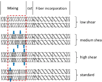
Huembert [44] experimented with the effect of screw design on the fiber length and the
mechanical properties of glass fiber reinforced PA6 D-LFT composites, which is based
on the same processing line with this work. As shown in Figure 2-11, four types of screws with different shear effect were used to produce the plaques with 30 wt.% fiber.
The standard screw design is the one used in this work. It is found that the average fiber
length decreases linearly as the shear effect of the screw increases. But the variation of
the mechanical properties is very limited.
Shimizu et al. [41] analyzed the fracture process of glass fibers contained in a glass fiber
reinforced PP composites, which occurs in the kneading zone of a twin-screw extruder. It
was found that the fiber length distribution depends upon the shear stress and the total
number of rotations.
Stade’s work [59] on two stage production-scale continuous kneaders help defining the
major processing factors on the fiber length of the finished products. Stade derived the
relationship between different processing parameters and fiber length empirically as
𝑘 =(𝐿2)(𝜌)(𝑓)(𝑁)(𝐴𝑓)
𝐹
(2-6)
where k is the key factor for the average glass fiber length in composites, L2 is the length
of the mixing section of extruders, ρ is the average density of the melt, f is the filling
ratio, N is the screw speed, Af is the free cross section of the extruder, and F is the feeding
rate of the composites. The relationship indicates that melt with higher density, higher
filling level, and higher screw speed can reduce the degradation of fiber length during the
compounding.
Fisa [39] performed an experiment to study the effect of viscosity, total work,
concentration on the fiber length and dispersion of glass fiber reinforced PP. The
degradation of fiber length was reported to be derived from both fiber and
fiber-melt interaction. The matrix viscosity has a more significant effect on the average fiber
Figure 2-10 Parameters involved in screw design: barrel diameter Db, centerline distance
A, clearance screw-barrel Cb, clearance screw- screw Cs and flight pitch P.
Czarnecki and White [40] proposed a mechanism for fiber breakage based on the
buckling during rotation in the shear flow. They also found the viscosity increasing is
only due to the enhanced viscous dissipation.
Yilmazer and Cansever [45] prepared glass fiber reinforced PA6 through injection
molding with different screw speed and feed rate. It is found that the increasing shear rate
through the alteration of screw speed and feed rate significantly reduce the fiber length.
Accordingly, the impact strength, the tensile modulus, and the tensile strength increase
while the global elongation decreases with the increasing shear rate.
Priebe and Schledjewski [46] studied the effect of processing parameters in a twin-screw
extruder on the fiber length of the materials extruded. It is found that utilizing the PP
products with higher viscosity led to higher fiber length but lower mechanical properties
which might be caused by some other effect of processing parameters on the material.
The high screw speed significantly degrades the fiber length as expected. But the effect
of screw configuration and fiber content were limited.
Ozkoc et al. [35] reported that the increasing screw speed reduced the fiber length and
had some negative effect on the mechanical properties. An increased extrusion
temperature had a positive effect on the fiber length and, therefore, improved the
mechanical properties.
These findings illustrate that the key factor to be controlled in the compounding process
in a twin-screw extruder is the shear flow of the melt. The adjustment of many
parameters can result in the variation of mechanical properties. However, the rule derived
from each work was based on a specific processing line and a specific material system,
which might not be directly applicable to other work that is based on a different
2.2.4
Environmental effect on the mechanical properties of LFT
composites
In service, the LFT components will be exposed to different environments, such as varied
temperature, water, sunshine and acid rain. If the LFT parts are exposed to these
environments for a long time or cyclically, the mechanical properties are likely to be
degraded. It is very important to quantify the extent of the degradation to ensure safety. A
great deal of research has been conducted to investigate the effect of these environmental
factors on both the microstructure and properties of LFTs.
Moisture can affect LFTs through attacking fiber, matrix, and interface (Figure 2-12). The absorbed water can promote creep and stress relaxation, generate residual stress and
osmotic pressure, and cause hydrolysis and chemical reaction. Fatigue degradation can be
accelerated by moisture as well, which can provide new paths for the moisture ingress.
Moisture damage starts near the surface with the growth of some local cracks [60]. The
degradation of LFTs is also related to the absorption of moisture through capillary action
and diffusion, which can be accelerated by voids and delaminations [61-63].
Hydrothermal aging has a significant effect on LFTs. Both strength and toughness were
shown to decrease as the immersion time increases [64]. Dry-wet cycling increased the
rate but hardly affected the maximum content of the water absorption [65]. Aggressive
temperature variation will also promote moisture absorption [64, 66]. It has been
observed that glass fiber degrades more than carbon fiber under the same condition [67].
Matrices are the main victim of moisture attack, resulting in plasticization, swelling,
hydrolysis and fiber-matrix debonding [68]. Plasticization can decrease the glass
transition temperature (Tg), soften the polymer and increase creep deformation, although
these effects are reversible on drying [60, 51, 67]. However, hydrolysis is irreversible,
which can degrade both stiffness and strength [64, 67]. Swelling can deteriorate the
bonding between fiber and matrix, which tends to form a continuous crack after cycling
At the fiber level, glass fiber is the most vulnerable to moisture attack. Moisture can
degrade glass fiber chemically, resulting in reduction of strength, fiber pitting and
stress-corrosion cracking [62-71].
Beg and Pickering [72] studied the hydrothermal aging behavior of virgin and
reprocessed wood fiber reinforced PP. After immersion in distilled water at 50°C over 9
months, the tensile strength, the Young’s modulus, and the hardness of samples
Figure 2-12 Local cracks caused by moisture absorbed in composites. [60]
decreased while the impact strength and the failure strain increased. The water uptake
was shown to decrease after reprocessing.
Valentin [73] investigated the hydrothermal behavior of glass fiber reinforced PA6.6
composites. When the temperature is lower than the Tg, Fick’s law can be employed to
model the water absorption process. When the temperature is higher than Tg, thermal
the shift of Tg. The same water uptake tends to have a greater effect on the mechanical
properties of short fiber composites than long fiber counterparts.
Compared with fibers, polymers are more susceptible to thermal effects. Lower
temperatures make the polymer more brittle to easily crack whereas the higher
temperature softens the polymer resulting in lower stiffness, chalking, and flaking of the
polymers [27, 74-91]. The softened matrix becomes deformable and less able to transfer
the stress to the fibers [63].
Thermal effects on the interface between fiber and matrix are the primary cause of the
mechanical degradation. Due to the distinct thermal expansion coefficients of fiber and
matrix, the shrinkage after cooling can generate a large stress concentration and residual
compressive stress. The former may serve as the crack initiating spot while the latter can
contribute to the interfacial shear strength [92-97]. The variation of temperature alters the
distribution of stress along the interface, which can have a complex effect on the
mechanical properties.
Thomason [27] researched the temperature dependence of the interfacial properties of
glass fiber reinforced PP composites at the temperature range of -40-100°C. The result
indicated that around 70% of the interfacial shear strength is derived from the residual
radial compressive stress which can be released by increasing temperature [78]. He also
reported that the heat deflection temperature (HDT) depends on both fiber length and
fiber concentration. Both longer fiber and higher fiber content can raise the HDT close to
the melting point of PP. That means the thermal effect on the mechanical properties of
LFT is correlated to the fiber length and the fiber concentration.
2.2.5
UD tape reinforcement on D-LFT composite
For a real part with complex geometry, the requirement of mechanical properties for
certain area, like one with stress concentration, might be higher than the rest. To
efficiently make use of the material, some local reinforcements may be required. With
However, this method may cause filling issues, especially for thermoplastic based
composites.
Another approach is to tailor the material properties locally. As mentioned above, once
the fiber content is determined for D-LFTs, the mechanical properties just depend on the
fiber orientation distribution within the whole product. Since the flow effect is difficult to
adjust, the mechanical properties of LFT product are also hard to locally improve.
As shown in Figure 2-13, the continuous fiber products with higher fiber fraction and more consistent fiber alignment have better performance but less freedom of design than
Figure 2-13 Comparison between the FRPs based on different fiber products. [100]
LFT, while LFTs have more freedom of design but lower performance. Borrowed from
GMT processing, tailored D-LFT is an innovative technique using the continuous fiber
tapes, in which all the fibers were continuous and aligned in the same direction, to locally
co-mold with D-LFT to take the benefits of both [98-108]. Additionally, the
configuration of the tapes including the type of materials, the fiber fraction, the stacking
Thattaiparthasarthy [107] compared the damage tolerance of LFT reinforced with ribs
and unidirectional tapes, respectively. Without changes in the processing, the co-molded
UD tapes enhance the flexural properties for equivalent rigidity compared to rib
reinforcement. The failure of LFTs got more ductile with tape reinforcement. The tape
reinforcement improves both flexural strength and failure displacement.
Grauel et al. [100, 101] co-molded a D-LFT automotive underbody shield with UD tapes
to improve the mechanical performance. The result clarified that tailored D-LFT
technique has a great potential to reduce both cost and mass with improved mechanical
properties. The co-molded tapes yield the parts with improved impact strength.
In Fang’s work [104], the effect of thickness of co-molded UD tapes on the mechanical
properties of the whole hybrid composite was studied. It was discovered that the UD
tapes could improve toughness significantly with little effect on modulus and strength.
Ruegg et al. [98] used different studies of structural components, implicit and explicit
finite element calculation with validation in a sled-test-front-crash with luggage retention
to derive the advantages of the combination of UD tapes and LFT over other current
solutions.
Prediction of mechanical properties of long fiber
thermoplastic
To predict the mechanical behavior of LFTs, many factors such as constituent material
properties, fiber volume fraction, fiber length distribution and fiber orientation
distribution need to be measured. It is crucial to understand the correlation between the
mechanical properties and these factors.
The elastic properties of UD composites are the best option to start with, in which
materials properties and fiber volume fraction are the only two variables. With an
assumption that the mechanical properties of UD are transversely isotropic, the
compliance matrix of UD [𝑆] can be determined by 5 independent constants: axial
transverse shear modulus (G23) and major Poisson’s ratio (ν12). The compliance is
expressed as below:
[𝑆] =
[
1/𝐸11 −𝜈12/𝐸11 −𝜈12/𝐸11 −𝜈12/𝐸11 1/𝐸22 −𝜈23/𝐸22 −𝜈12/𝐸11 −𝜈23/𝐸22 1/𝐸22
0 0 0 0 0 0 0 0 0 0 0 0
0 0 0 0 0 0
1/𝐺23 0 0
0 1/𝐺12 0
0 0 1/𝐺12]
(2-7)
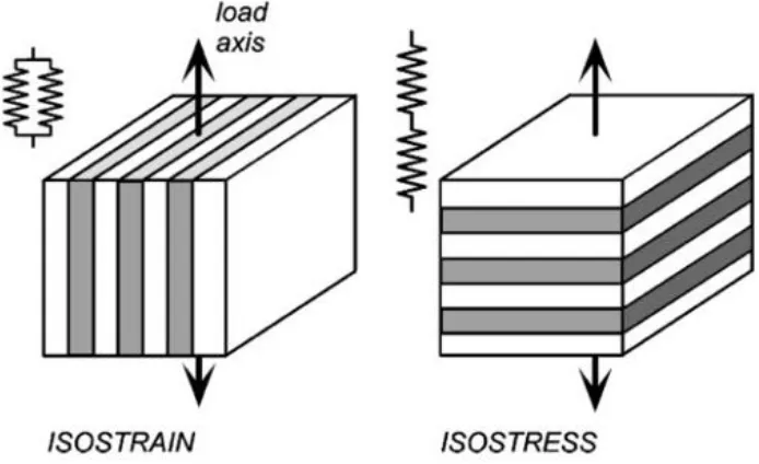
The rule of mixture (ROM) is the most basic approach being used to calculate these 5
constants. It is based on two types of slab model as shown in Figure 2-14: iso-strain model (Voigt model) and iso-stress model (Reuss model) [109, 110].
Two types of slabs represent the fiber and matrix with an assumption of perfect bonding.
In the iso-strain model, fiber and matrix have the same strain in the load direction. Then
the axial Young’s modulus and major Poisson’s ratio can be derived as follows:
𝐸11 = 𝑉𝑓∙ 𝐸𝑓+ 𝑉𝑚∙ 𝐸𝑚 (2-8)
𝜈12= 𝑉𝑓∙ 𝜈𝑓+ 𝑉𝑚∙ 𝜈𝑚 (2-9)
Where, 1 is the axial direction, 2 is the transverse direction, 𝑉 is the volume fraction, 𝐸 is
the Young’s modulus, 𝜈 is Poisson’s ratio, subscript 𝑓 represents the fiber and
subscript 𝑚 represents the matrix. In the iso-stress model, fiber and matrix bear the same
stress in the load direction, from which the shear modulus and transverse Young’s
modulus can be derived as follows:
𝐸22 = 𝐸𝑓∙𝐸𝑚
𝐸𝑚∙𝑉𝑓+𝐸𝑓∙𝑉𝑚 (2-10)
𝐺12 = 𝐺𝑓∙𝐺𝑚
𝐺𝑚∙𝑉𝑓+𝐺𝑓∙𝑉𝑚 (2-11)
The prediction for 𝐸11 and 𝜈12 using ROM matches well with experimental result while
that for 𝐸22 and 𝐺12 is often lower than the experimental results. That is caused by the
inhomogeneous stress distribution within the matrix. To fix this problem, several models
were developed to predict E22 and G12 with different assumptions, such as Modified Rule
assemblage method (CCS) [113], Mori-Tanaka model [114], Bridging model [115, 116]
and Eshelby method. Among these, as taking account of the enhanced fiber load bearing,
the Halpin-Tsai model is the most successful and widely employed. The empirical
expression is shown as follows:
𝐸𝑢𝑑𝑖 = 𝐸𝑚∙ (1+𝜁𝑖𝜂𝑖𝑉𝑓
1−𝜂𝑖𝑉𝑓 ) (2-12)
with 𝜂𝑖 = ( 𝐸𝑓 𝐸𝑚−1
𝐸𝑓 𝐸𝑚+𝜁
) (2-13)
Where 1=2L/d and2=2, 𝐸𝑚 is the Young’s modulus of matrix, 𝑉𝑓 is the fiber volume
fraction. L is the fiber length and d is the fiber diameter.
Figure 2-14 Voigt (iso-strain) model and Reuss (iso-stress) model for composite material elasticity.
Since the fibers in LFTs are discontinuous and partially aligned in the flow direction, the
prediction of the mechanical properties needs to take both fiber length distribution (FLD)
and fiber orientation distribution (FOD) into account. Currently, three approaches are
model developed by Cox [117] and improved by Krenchel [118]. The expressions are
shown as follows:
𝐸11 = 𝑘1𝑘2𝐸𝑓𝑉𝑓+ 𝐸𝑚(1 − 𝑉𝑓) (2-14)
with 𝑘1 = [1 − tanh( 𝛽𝐿
2) 𝛽𝐿
2
] (2-15)
𝛽 =2
𝑑[ 2𝐺𝑚
𝐸𝑓ln √ 𝜋 𝑋𝑖𝑉𝑓
] (2-16)
𝑘2 = ∑ 𝑎𝑖 𝑖cos4𝜃𝑖 (2-17)
Where 𝐸𝑓 and 𝐸𝑚 are the Young’s moduli of fibers and matrix, respectively. The effect
of FLD and FOD were involved by inducing fiber length factor 𝑘1 and fiber orientation
factor 𝑘2. 𝐿 and 𝑑 are the length and diameter of fibers, respectively. 𝑋𝑖 depends on the
geometrical packing arrangement of fibers and can be set as 4 [24]. 𝑉𝑓 is fiber volume
fraction. 𝑎𝑖 represents the fiber proportion making an angle 𝜃𝑖 with the load direction.
The second method is based on the Halpin-Tsai model [29]. As mentioned before,
Halpin-Tsai has already involved the effect of fiber length. Young’s modulus in
longitudinal 𝐸𝑈𝐷1and Young’s modulus in transverse directions 𝐸𝑈𝐷2 of unidirectional
discontinuous fiber can be predicted based on equations (2-11) and (2-12). With the fiber
orientation factor 𝑘2 calculated by equation (2-16), the Young’s modulus of partly
aligned discontinuous fiber composites can be predicted as:
𝐸c = 𝑘2𝐸𝑈𝐷1+ 𝐸𝑈𝐷2(1 − 𝑘2) (2-18)
The third approach is based on laminate analogy approach (LAA) with an assumption
that the specimen is shell-like to enable the condition of a planar FOD. Developed by Fu
and Lauke [119] with an inspiration from paper physical approach (PPA), the expression
𝐸11=
𝑄11𝑔∙𝑄22𝑔−𝑄12𝑔2
𝑄22𝑔 (2-19)
𝐸22 =𝑄11𝑔∙𝑄22𝑔−𝑄12𝑔 2
𝑄11𝑔 (2-20)
With 𝑄𝑖𝑗𝑔= ∫ ∫𝜃𝑚𝑎𝑥𝑄𝑖𝑗 𝑓(𝐿)𝑔(𝜃)𝑑𝐿𝑑𝜃
𝜃𝑚𝑖𝑛
𝐿𝑚𝑎𝑥
𝐿𝑚𝑖𝑛 (2-21)
Where 𝑄𝑖𝑗𝑔’s are overall stiffness terms obtained by integrating the transferred stiffness
matrix of aligned composite 𝑄𝑖𝑗 along with fiber length 𝑓(𝐿) and orientation 𝑔(𝜃)
density functions.
Fu and Lauke [120] also developed an approach to predict the tensile strength of LFT by
accounting for the dependence of the ultimate fiber strength and the critical fiber length
on the inclination angle θ, which is based on modified rule of mixture. The expression is
shown as follow:
σ = 𝑘2𝑉𝑓𝜎𝑢𝑓(∫ 𝑓(𝐿) 𝐿𝑐
0 [
𝐿
2𝐿𝑐𝑟] 𝑑𝐿 + ∫ 𝑓(𝐿)
∞
𝐿𝑐𝑟 [1 −
𝐿𝑐
2𝐿] 𝑑𝐿) + 𝜎𝑢𝑚(1 − 𝑉𝑓) (2-22)
Where 𝜎𝑢𝑓 is the ultimate fiber tensile strength, 𝐿𝑐 is the critical fiber length which can
be calculated based on Equation 2-4 and 𝜎𝑢𝑚 is the tensile strength of the matrix.
Summary
Fiber content, processing parameter and temperature can all affect the mechanical
properties of LFT. But the previous findings about the correlation between these factors
and the mechanical properties of LFT are based on different processing lines and
different material systems. For the material investigated in this work, the new
combination of PA6 with glass fiber for D-LFT and the much long fibers might lead to
different rules. Therefore, it is worth to evaluate the effect of fiber content, processing
parameter, temperature on the mechanical properties and determine a proper way to apply
Chapter 3
3
Experimental
Materials
PA6 (Ultramid 8202HS) provided by BASF and glass fiber (JM 886) provided by John
Manville (JM) were used in this work. The Ultramid 8202 HS is a heat stabilized, low
viscosity, general purpose PA6 which possesses the combination of strength and
toughness and has excellent chemical and abrasion resistance. The JM 886 glass fiber is
characterized by a pioneering reactive sizing designed for structural thermoplastic
composites with polyamide engineering polymers. Physical and mechanical properties of
these two products are listed in Table 3-1.
Preparation
3.2.1
Dieffenbacher D-LFT-ILC line
Preparation of all the specimens involved in this work was performed at the
FPC@Western. The key equipment was a Dieffenbacher direct long fiber reinforced
thermoplastics in-line compounding (D-LFT-ILC) line, of which the schematic is shown
in Figure 3-1. During processing, polymer granules and additives were dried and fed into the first extruder to undergo a thorough compounding. Then the molten matrix blend was
extruded out through a film die into the second extruder. Simultaneously, continuous
fibers were integrated from the top of the melt film and continuously pulled into the
second extruder by the screw rotation. In the second extruder, the continuous fibers were
chopped by a specially designed cutting element of the twin-screw and smoothly
dispersed by shear effect of the melt. Mixed compounds were continuously coming out
through a servo die and cut into charges by a shear blade. The charges were kept warm on
an insulated conveyor and transferred manually into a tool to undergo compression
molding. Compared with other competing directly compounded long fiber reinforced
thermoplastic (D-LFT) lines, separation of polymer plasticizing and fiber integration is
the most attractive characteristic of this D-LFT-ILC line. High screw speed and screws
Table 3-1 Properties of PA6 (Ultramid 8802HS) and glass fiber (JM 886) used in this work.
PA6 Glass fiber
Supplier BASF Johns Manville
Product Ultramid 8802HS JM 886
ρ (g/cm3) 1.13 2.63
E11 (GPa) 2.7 70
E22 (GPa) 2.7 70
G12(GPa) 0.93 30
τ (MPa) 45 866
σt (MPa) 78 1500
ν12 0.45 0.17
![Table 2-1 Properties of some commonly used resins. [1]](https://thumb-us.123doks.com/thumbv2/123dok_us/1968021.1259620/19.612.119.539.113.460/table-properties-commonly-used-resins.webp)