Compact Two-Element MIMO Antenna Based on Half-Mode SIW
Cavity with High Isolation
Bing-Jian Niu* and Jie-Hong Tan
Abstract—A compact two-element multiple-input-multiple-output (MIMO) antenna with high isolation is proposed in this paper. It is based on a half-mode substrate-integrated-waveguide (SIW) cavity where three edges are shorted by metallic vias, and one edge is opened to radiate cavity energy into free space. Fed by coaxial ports, two antenna elements are constructed in the SIW cavity, and a narrow T-shaped slot is introduced to enhance the isolation between them. High port isolation can be achieved by adjusting the slot length although these antenna elements are connected with each other. A prototype has been fabricated and measured. With the compact cavity size of 0.22λ0 ×0.44λ0, the fabricated antenna achieves the operating frequency of 3.51 GHz, enhanced isolation of 18.0 dB, low envelope correlation coefficient of 0.006, peak gain of 5.2 dBi, and high efficiency of 82.6%. Therefore, the proposed MIMO antenna has potential applications for wireless communication.
1. INTRODUCTION
With further requirements of high transmission rate, multiple-input-multiple-output (MIMO) antennas have been widely introduced in current fourth-generation (4G) and forthcoming fifth-generation (5G) wireless communication systems [1]. It can provide multiplexing gain to increase channel capacity and can also offer diversity gain to improve link reliability [2]. However, two major challenges are faced for the design of compact MIMO antennas. One is to minimize antenna elements, and the other is to enhance the isolation between them [3].
Recently, the half-mode (HM) substrate-integrated-waveguide (SIW) cavity has drawn special attention from antenna designers [4–6]. Compared to the conventional SIW cavity, its size is reduced by half, but comparable characteristics are maintained, in terms of resonant frequency, field distribution, and radiation performance [7]. However, two antenna elements constructed in an HM SIW cavity have been rarely studies up to now. On the other hand, a number of techniques have been proposed to enhance the isolation between antenna elements, such as optimization of antenna configuration [8], introduction of isolating elements [9, 10], and utilization of a decoupling network [11]. However, MIMO antennas adopting these methods usually have large overall size, complex structures, and low radiation efficiency [12].
In this paper, a compact two-element MIMO antenna based on a half-mode SIW cavity is proposed. High isolation can be achieved by introducing a narrow T-shaped slot in the cavity although these antenna elements are connected with each other. The S-parameters comparison, electric-field distribution, and parametric study have been discussed to validate effectiveness of the proposed design. The proposed antenna with compact size, high isolation, and good radiation performance is attractive for practical applications.
Received 1 May 2019, Accepted 3 July 2019, Scheduled 15 July 2019
* Corresponding author: Bing-Jian Niu ([email protected]).
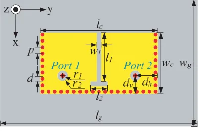
widthw1. It is located in the center of the cavity and cut from the opened edge. Two antenna elements are separately excited by port 1 and port 2 where their inner pins (r1) and outer conductors (r2) are connected to the top and bottom planes of the SIW cavity, respectively. By moving offset distances (dh
and dv) from perpendicular shorted edges, good antenna matching can be achieved.
The proposed antenna has been designed and optimized by using ANSYS HFSS. The overall structure is completely printed on a single-layer F4B-2 substrate with relative permittivity 2.5 and thickness 3 mm. Parameters’ dimensions arelg = 67.5 mm,wg = 45.0 mm,lc = 37.8 mm,wc= 18.9 mm,
l1 = 14.5 mm,l2= 3.6 mm, w1 = 1.5 mm,dv = 4.9 mm, dh = 7.4 mm,d= 0.6 mm, andp= 1 mm.
Figure 1. Configuration of the proposed two-element MIMO antenna based on a HM SIW cavity.
3.2 3.3 3.4 3.5 3.6 3.7 3.8
Frequency (GHz) 0
-10
-20
-30
S
-parameters (dB)
S without slot S with slot S /S with slot
21
11 22 21
Figure 2. Simulated S-parameters with and without the narrow T-shaped slot.
2.2. Operating Principle
High port isolation is crucial for MIMO antennas. In the proposed design, the narrow T-shaped slot can serve as the isolating element and reduce the mutual coupling between antenna elements. The simulated S-parameters with and without the slot are shown in Figure 2 for a comparison. Owing to a symmetrical structure, S11is the same asS22, resonating at 3.5 GHz with 10-dB bandwidth of 70 MHz. As can be seen, before adding the isolating slot, the mutual coupling between antenna elements is quite high within the frequency of interest. By introducing the slot, the port isolation S21 is significantly enhanced to better than 19.8 dB, satisfying the requirement of typical MIMO antennas. Therefore, although these two antenna elements are constructed in an HM SIW cavity and contacted with each other, high isolation can be achieved in the proposed design.
To investigate the operating principle of the proposed MIMO antenna, electric-field distributions on the bottom plane of the SIW cavity are plotted in Figure 3. When port 1 is excited, strong field is concentrated in the left part of the cavity while negligible field is distributed in the right part. A similar distribution can also be observed when port 2 is excited. It can be concluded that cavity energy input by one port is little transmitted to the other port, but mainly radiated into free space through the opened edge and narrow slot.
(a) (b)
Figure 3. Electric-field distributions on the bottom plane of the SIW cavity. (a) When port 1 is excited. (b) When port 2 is excited.
3.2 3.3 3.4 3.5 3.6 3.7 3.8
Frequency (GHz) 0
-10
-20
-30
S
(dB)
21
at l = 13.6 mm
at l = 13.9 mm
at l = 14.2 mm at l = 14.5 mm
1 1
1 1
Figure 4. Simulated port isolation S21 by varyingl1.
isolation between antenna elements is determined by the slot length. As l1 increases from 13.6 mm to 14.5 mm, S21 is enhanced from 9.7 dB to 19.8 dB. This simple and effective technique of isolation enhancement makes the proposed design attractive for practical applications.
3. EXPERIMENTAL VERIFICATION
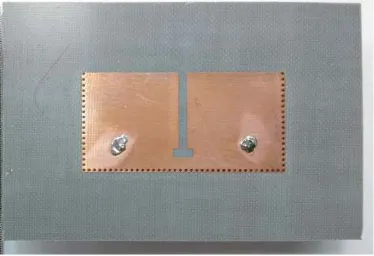
As shown in Figure 5, an antenna prototype has been fabricated to validate the proposed design and analysis. The cavity size is 0.22λ0×0.44λ0, which is very compact. TheS-parameters of the fabricated
Figure 5. Fabricated prototype.
3.2 3.3 3.4 3.5 3.6 3.7 3.8
Frequency (GHz) 0
-10
-20
-30
S
-parameters (dB)
simulated |S | measured |S |
simulated |S |
measured |S |
11
21 11
21
Figure 6. Simulated and measured S
symmetrical structure of the proposed design, only port 1 is excited while port 2 is terminated with a 50 Ω load. The measured patterns are in a good agreement with the simulated ones in two orthogonal cut planes. For this antenna element,xoz-plane is theE-plane with a tilted unidirectional pattern, and yoz plane is the H-plane with maximum radiation in the broadside direction.
In order to evaluate the MIMO performance of the proposed antenna, the envelope correlation coefficient (ECC) has been calculated from 3-D radiation patterns with the assumption of a uniform incident wave environment [12]. As shown in Figure 8, both the simulated and measured ECCs are below 0.006 over the entire operating band, which is acceptable for MIMO operation.
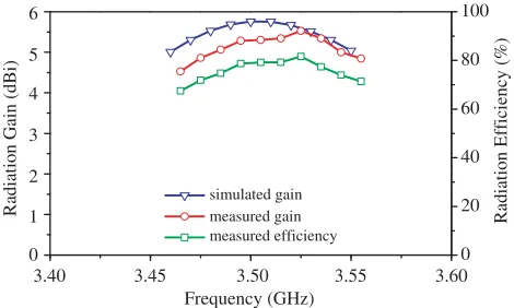
The simulated and measured antenna gains excited by port 1 are shown in Figure 9. The measured peak gain is 5.2 dBi, which is slightly less than the simulated value about 0.3 dB. This discrepancy may
(a) (b)
0
30
Unit: dBi Unit: dBi
60 90 120 150 180 210 240 270 300 330 0 30 60 90 120 150 180 210 240 270 300 330 simulated gain measured gain
10 0 -10 -20 -10 0 10 10 0 -10 -20 -10 0 10
Figure 7. Simulated and measured total-gain radiation patterns at (a)xoz-plane and (b)yoz-plane.
Frequency (GHz)
3.40 3.45 3.50 3.55 3.60
0.008
0.006
0.004
0.002
0.000
Envelope Correlation Coefficient
simulated ECC measured ECC
Figure 8. Simulated and measured ECC.
0 20 40 60 80 100 Frequency (GHz)
3.40 3.45 3.50 3.55 3.60
6
5
4
3
2
Radiation Gain (dBi) 1
0
simulated gain measured gain measured efficiency
Radiation Efficiency (%)
be attributed to the additional loss of SMA connectors. In addition, radiation efficiency has also been measured by calculating the receiving radiation power with the angular sampling interval of 2 deg over the input power [13, 14]. The measured efficiency has the highest value of 82.6% at 3.52 GHz.
4. CONCLUSION
A compact MIMO antenna with high isolation is presented. It consists of a rectangle HM SIW cavity, a narrow T-shaped slot, and two coaxial feeding ports. The isolation between antenna elements can be easily enhanced by adjusting the slot length. This simple and effective method of isolation enhancement makes the proposed design attractive for practical applications. According to measured results, the proposed two-element MIMO antenna based on an HM SIW cavity exhibits attractive characteristics of compact size, enhanced isolation, unidirectional pattern, low ECC, and high radiation performance.
REFERENCES
1. Zhao, A. and Z. Ren, “Size reduction of self-isolated MIMO antenna system for 5G mobile phone applications,”IEEE Antennas and Wireless Propagation Letters, Vol. 18, No. 1, 152–156, Jan. 2019. 2. Yang, S. and L. Hanzo, “Fifty years of MIMO detection: The road to large-scale MIMOs,” IEEE
Communication Surveys & Tutorials, Vol. 17, No. 4, 1941–1988, 4th Quart., 2015.
3. Zhao, Y., F.-S. Zhang, L.-X. Cao, and D.-H. Li, “A compact dual band-notched MIMO diversity antenna for UWB wireless applications,” Progress In Electromagnetics Research C, Vol. 89, 161– 169, 2019.
4. Liu, F., Z. Xu, D. C. Ranasinghe, and C. Fumeaux, “Textile folded half-mode substrate-integrated cavity antenna,” IEEE Antennas and Wireless Propagation Letters, Vol. 15, 1693–1697, 2016. 5. Zhu, Y.-Z., “A novel circularly polarized half mode circular substrate integrated waveguide antenna
using meandered strip feeding technique,”International Journal of RF and Microwave Computer-Aided Engineering, Vol. 26, No. 8, 668–673, 2016.
6. Lou, Q., R. Wu, F.-G. Meng, and P. Yin, “Realizing frequency reconfigurable antenna by ferrite-loaded half-mode SIW,” Microwave and Optical Technology Letters, Vol. 59, No. 6, 1365–1371, 2017.
7. Nguyen-Trong, N. and C. Fumeaux, “Half-mode substrate-integrated waveguides and their applications for antenna technology: A review of the possibilities for antenna design,” IEEE Antennas Propagation Magazine, Vol. 60, No. 6, 20–31, Dec. 2018.
8. Yan, S., P. J. Soh, and G. A. E. Vandenbosch, “Dual-band textile MIMO antenna based on substrate-integrated waveguide (SIW) technology,” IEEE Transactions on Antennas and Propagation, Vol. 63, No. 11, 4640–4647, Nov. 2015.
9. Zhang, Y. and B. Niu, “Compact ultrawideband (UWB) slot antenna with wideband and high isolation for MIMO applications,”Progress In Electromagnetics Research C, Vol. 54, 9–16, 2014. 10. Zhai, G., Z. N. Chen, and X. Qing, “Enhanced isolation of a closely spaced four-element MIMO
antenna system using metamaterial mushroom,”IEEE Transactions on Antennas and Propagation, Vol. 63, No. 8, 3362–3370, Aug. 2015.
11. Wang, Z., L. Zhao, A. Chen, and Y.-Z. Yin, “A second order decoupling design using a resonator and an interdigital capacitor for a MIMO antenna pair,” Progress In Electromagnetics Research Letters, Vol. 67, 19–24, 2017.
12. Nadeem, I. and D. Choi, “Study on mutual coupling reduction technique for MIMO antennas,” IEEE Access, Vol. 7, 563–586, 2019.
13. Niu, B. and J.-H. Tan, “Bandwidth enhancement of low-profile SIW cavity antenna with bilateral slots,”Progress In Electromagnetics Research Letters, Vol. 82, 25–32, 2019.