Technology (IJRASET)
A Novel Control Strategy for a PV Grid Connected
Voltage VAR Compensation using PI and PI Fuzzy
Controller
BhumikaBarange1, Rejo Roy2
1
Student, 2Assistant Professor
Department of Electrical Engineering, Rungta College of Engineering Bhilai, Bhilai (CG), India
Abstract:-Three-phase grid-connected converters are widely used in renewable and electric power system applications. Traditionally, grid-connected converters are controlled with standard decoupled d-q vector control mechanisms. However, recent studies indicate that such mechanisms show limitations in their applicability to dynamic systems. This thesis investigates how to mitigate such restrictions using a Fuzzy-PI to control a grid-connected rectifier/inverter. The Fuzzy-PI implements a dynamic rule book and fuzzy rules. To enhance performance and stability under disturbance, additional strategies are adopted, including the use of integrals of error signals to the network inputs and the introduction of grid disturbance voltage to the outputs of a fuzzy system. The performance of the Fuzzy PI controller is studied under typical vector control conditions and compared against conventional vector control methods, which demonstrates that the neural vector control strategy proposed in this paper is effective. Even in dynamic and power converter switching environments, the fuzzy vector controller shows strong ability to trace rapidly changing reference commands, tolerate system disturbances, and satisfy control requirements for a faulted power system. Keywords- PI Controller, D-Q axis parameter, grid connected converter, decouple vector control
I. INTRODUCTION
The Environmental friendly renewable energy technologies such as solar energy and wind energy based systems are among the fleet of new generating technologies driving the need for distributed generation of electricity. Power Electronics has ignited the next technical revolution and enables the connection of distributed generation (DG) systems to the power system. Hence the increasing power demand will be met by Distributed Generation (DG) system which is founded on renewable energy sources such as wind power, solar power and small hydro power etc. [1] -[2]. In order to ensure sinusoidal current injection into the grid, these systems need to be controlled. Simply, their intermittent characteristics give them poor controllability [3].Grid connected inverter plays a critical part in maintaining voltage at the point of common coupling (PCC) constant.The grid code requirements such as grid stability, fault ride through, force control and grid synchronization, and so forth should be touched by the power plant operator for the dependable performance of utility grid based on DG system. The synchronization with utility voltage vector is the major event associated with the DG system [4]. The information about the phase angle of utility voltage is tracked accurately to control the flow of active and reactive power and to move around on and off power devices.
A form of solar energy is wind. The wind flow patterns are modified due to the bodies of water and vegetation, uneven heating of the air by the sun, wind flow, the earth terrains. Wind turbine converts the kinetic energy in the wind into mechanical then to electrical by
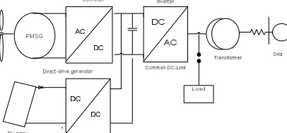
[image:2.612.221.424.614.708.2]Hence the role of the hybrid generation system is better than individual wind or individual PV generation system [6]. It overcomes the demerits of individual system. The system reliability can be increased by the grid interface of the hybrid generation system.
Technology (IJRASET)
In this system, there is a wind turbine, the output of the wind turbine is fed to the permanent magnet synchronous generator. The production of the wind system is in AC so we need AC to DC convertor to change the AC output into DC. Similarly, on the PV side the output of the PV array is connected to a DC-DC boost converter to produce the output voltage up to a desired point.And the yield of PV and wind are connected to a common DC link voltage.The common DC link voltage will be connected to the DC to AC converter and the yield of the inverter is synchronizing with grid. This inverter converts DC power from the PV array and the wind turbine into AC power and it maintains the potential difference and frequency equal to the grid voltage and frequency. Renewable energy sources are playing an intense role in the today power scenario; due to rapid development of future energy demand and depletion of fossil fuels. Renewable energy sources include wave energy, small hydro, wind power, PV system, biomass, etc. Wind energy system is the most promising beginning of energy among all renewable energy sources due to economic viability [11]. Distributed generation (DG) based on renewable energy sources is mostly small scale power generation units (typically ranges from 20 kilowatt to 20 MW) and they are sited at the user end without the use long distance transmission line.As a result of this, the transportation cost of generation is cut down and consumption levels are tight to each other.It is practicable to implement interfaces which have the power to be operated in isolation called micro grids or grid connected [12].
A. Small Signal Model of 1-Φ Inverter
The primary aim of studying small signal model is to predict low frequency component present in the output voltage [6].The magnitude and form of this component depend not merely on the duty cycle variation, but besides the frequency response of the convertor.It is obtained by applying a deliberate perturbation around the operating level and then linearizing it at that level. The 1-Φ
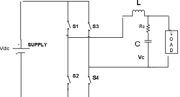
[image:3.612.223.399.329.424.2]full bridge VSI system is illustrated in Fig.4.1.
Fig.1.1 Schematic diagram of 1-Φ inverter to be modeled
The inverter in the above figure is being modeled and analyzed with an LC filter on the load side which considers R as load. Let us consider L is filter inductance Is damping resistor, C is filtered capacitor, or is loaded resistance, , , , Are switches and
The main purpose of using the damping resistor is to damp out the oscillations occurring due to the use of LC filter resonance.
Case 1: When switches S andS are ON, then circuit is shown in Fig.1.2.
Fig 1.2 Equivalent circuit when switches S andS are ON
Applying KVL in Fig 2.2
L = - (1.1)
i = i - i
C = i - (1.2)
[image:3.612.189.412.522.608.2]Technology (IJRASET)
Fig 4.3 Equivalent circuit when switches S andS are ON
L = - (1.3)
i = -i - i
C = -i - (1.4)
Let us consider the average value of the inductor current and capacitor voltage, over a switching period T
L = d < − > Ts + < - > Ts (1.5)
Where d= duty cycle and = 1-d
And C = d<i - >Ts + < -i - >Ts (1.6) Let us define an operating point as follows
Duty cycle = D Input Voltage = Output Voltage = Capacitor Voltage = V
Inductor Current = i
Source Current = i
In order to design a small signal model we will have to consider a small perturbation along with its steady state values. < >Ts = +
< >Ts = + < D >Ts = D + < >Ts = + < >Ts = +
Put above values in equation (1.5) and (1.6). On simplification the equation gives rise to a multiplication of steady state value terms along with linear and nonlinear terms. Multiplication of perturbation terms can be neglected as its results are very small. And then the resulting expression would be
L = (D- ) - (D- ) + 2
L = (2D- 1) - (2D-1) + 2 (1.7) Similarly
C = (2D-1) - + 2 (1.8)
[image:4.612.190.419.623.707.2]From the equations (4.7) & (4.8) small signal model of the inverter is derived and is depicted in Fig.4.3.
Technology (IJRASET)
From Fig 1.3 it can be observed that a small signal ac current is drawn by the inverter out of the input voltage source . As the concerned VSI of bridge type configuration the duty cycle is (2D-1). The term (2D -1) is dependent on the inductor current variation And is represented by a subordinate source. The term 2 is driven by the control variations and is modeled by an independent source. This is an equivalent circuit that models the low frequency small signal variations in the inverter waveforms and it can be worked out for using conventional analog circuit analysis techniques to get the inverter transfer functions.
B. Control Strategy for 1-Φ Inverter
A control strategy is to be used to produce the output potential of the inverter being sinusoidal and hence to reduce THD in it.In this work an ACC [7] has been enforced to control the inductor current and PI controller or Resonant controller for controlling output voltage.
1) Proportional Resonant (PR) controller:In order to alleviate the shortcomings associated with conventional PI controller a novel controller proportional resonant controller [PR] is introduced recently.
PR controllers are equivalent to conventional PI controller implemented in two synchronous rotating frame (positive sequence and negative sequence) and thus able to track sinusoidal references with variable frequency of both positive and negative sequences with zero steady state error.The transport office of PR controller can be gained by applying an internal control model with modified state transformation or frequency domain approach. [16]
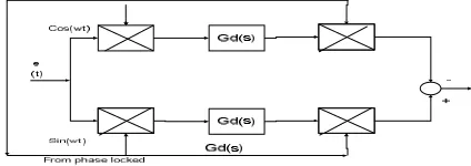
As d-q transformation cannot be given to single phase system directly, a new method is adopted by multiplying the sine and cosine functions resulting from phase locked loop with the feedback error signal e (t) as indicated in Fig. 1.4.
[image:5.612.198.410.368.443.2]This accomplishes the same matter of translating the component at a chosen frequency to DC quantity leaving others to use quantities.Let us assume the feedback error signal contains a fundamental component along with the fifth harmonic component which is expressed by the equation (3.1)
Fig. 1.4 Single phase equivalent presentation of PR controller
This achieves the same issue of translating the component at a chosen frequency to DC quantity leaving others to use quantities.Let us accept the feedback error signal contains a fundamental component along with the fifth harmonic component which is shown by equation (1.9)
e(t) = cos(ωt + ϕ ) + cos(5ωt + ϕ ) (1.9)
Where ω, Φ1, Φ5 are the fundamental angular frequency, fundamental and fifth harmonic phase shifts respectively.
Multiplying equation (1.9) by sin (ωt) and cos (ωt) respectively equations (1.10) and (1.11) are derived
e(t) cos(ωt) = {cos (ϕ) + cos(2ωt + ϕ )} + {cos(6 ωt + ϕ ) + cos(4ωt + ϕ ) (1.10)
e(t) sin(ωt) = {sin (−ϕ ) + sin(2ωt + ϕ )} + {sin(6 ωt + ϕ ) + sin(-4ωt - ϕ )} (1.11)
From equations (1.10) and (1.11) it is observed that the fundamental component of the feedback error signal is a constant as it is a function of phase shift ϕ only. The only complication with this equivalent single-form conversion is that the chosen frequency
component not only appears as a dark quantity in the synchronous form, it also leads to harmonic terms at a frequency of 2ω, unlike
three phase synchronous d–q conversion.Still, passing equations (1.10) & (1.11) through integral blocks would still push the fundamental error amplitude E1 to zero, caused by the infinite gain of the integral blocks.
Technology (IJRASET)
transforming the controller G (s) from the synchronous to the stationary frame is also possible. The as quantity which includes the DC controller G (s) can be expressed by equation (1.12) after taking positive and negative sequence components into consideration.
G (s) = G (s) (s + jω) - G (s) (s - jω) (1.12)
Where, G (s)is the equivalent stationary frame transfer function.
For ideal IntegratorG (s) = and by substituting in equation (1.12) G (s) can be derived as follows
G (s) = ( )
( ) = (1.13)
For non-ideal Integrator, G (s) = and by substituting in equation (3.4)
G (s)can be derived as follows
G (s) = ( )( ) = (1.14)
Where, Ki and ωcare the integral controller gain and cutoff frequency respectively.
Equation (1.13) when grouped with a proportional term Kp gives the ideal PR controller with an infinite gain at the ac frequency ω
(Fig.4.5), and no phase shift and gain at other frequencies. For Kp, it is tuned in the same way as for a PI controller, and it basically determines the dynamics of the system in terms of bandwidth, phase and gain margin.
An interesting feature of the PR controller as harmonic eliminator is that it does not affect the dynamics of the fundamental PR controller, as it compensates only for frequencies that are very close to the selected resonant frequencies.
Current Control Scheme: An ACC is having an advantage over a peak current controller of adding a high increase in the forward control path and thus reduces the steady state error [7].Here the inductor current has been averaged over a shift point. And digital implementation of the current controller introduces a sampling delay. This delay yields 1 0 phase lag at the half of switching frequency. So, digital delay of one switching period is introduced in the current loop whose transfer function is given by Eq (1.15) based on Paddes expansion.
Fig.1.5 Control loop for ACC strategy
The reference value of inductor current is generated from the output of voltage control loop discussed in the next section. A current sensor is being used to sense inductor current and its gain Ri is considered for controller design. In this research work its value is taken as 0.2. The transfer function of the design of the current loop is the ratio between duty cycle to output current ( ) and is given by equation (1.11) which has been deduced from small signal model of inverter (Fig.1.4)
by keeping = 0.
( )= (1.15)
Where Z= load impedance is given by equation Z=( . )
. ( )
Technology (IJRASET)
As shown in the bode plot of Gi d(s)phase cross over frequency is 10kHz which gives flatter response to inductor current which is due to implementation of ACC.
For the current loop a proportional and resonant controller has been chosen. An ideal resonant controller adds an infinity gain to the control loop so as to reduce the steady state errorThe transfer function of choosing proportional and resonant control is given by equation (4.17)
G (s) = + (1.17)
For this application gain K1=100, bandwidth B1=2.π rad and the resonant angular frequency ω1=2.π.50 rad/sec. It can be observed
from Fig.3.3 that at resonant frequency (i.e 50Hz) a high gain is being added to loop and there is a phase drop simultaneously. The current loop is having a phase margin of 0 and gain crossover frequency is 1.9 kHz. The value of Kp has been chosen as 0.3859.
Voltage Control Scheme: The voltage controller is meant for controlling the output voltage of the inverter and it generates a reference current for the current controller (ACC). In this research work with two types of controllers for voltage control have been implemented and compared.
G = (1.18)
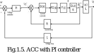
PI Voltage Controller: The PI controller produces a system response with minimized steady state error in the output. The integral action reduces the error produced by the proportional action. The control scheme of the inverter including voltage control. Like current sensor, a voltage sensor of gain β is used to sense the output voltage of the inverter. In this work the gain of the voltage
[image:7.612.230.394.399.493.2]sensor is assumed as 0.006.
Fig.1.5. ACC with PI controller
The value of the gain of the PI controller has been derived from the step response of the plant transfer function and is given by equation (1.19) and the bode plot of the voltage loop with PI controller is given in the Fig.1.3.
PI (s) = 0.20448. (1.19)
The transfer function of the voltage loop with PI controller is given by equation (4.20) which has been deduced from Fig.4.11 From Fig 4.11 it was found that the gain crossover frequency of the voltage loop is 0 Hz and the phase margin is 1.
T = G (s). β. PI (s) (1.20)
Technology (IJRASET)
Fig.1.6 ACC with P+Resonant controller
The values of the gains of odd harmonics and their bandwidths have been given in the Table 1.1 [14]. Harmonics Gains Bandwidth
1 28 Π
3 5 3 π
5 8 5 π
7 6 7 π
9 4 9 π
From the bode plot of the voltage loop with proportion and resonant controller as shown in Fig.4.14 it can be observed that the phase is zero at the harmonic frequencies, this means that the controller has a resistive behavior. The decreasing value at high frequencies allows a reduction in the harmonic voltage and hence reduction in voltage THD.
From the bode plot, the gain crossover frequency is found to be 10 kHz and the phase margin is 80°. The system parameters of the concerned 1-Φ inverter are given in Table.1.2.
Boost Converter: DC-DC Converter is advisable that accepts a DC input voltage and produce a desired DC output voltage. The output produced is at a different voltage level, then the input. There are three types of DC-DC converters that are buck, boost and buck-boost Converter and hear in this Boost converter is used to step up the PV output. Also DC-DC converters are used to provide noise isolation and power bus regulation.
S. No Parameter Value
1 DC link voltage (Vdc) 400 V
2 Inverter Output Voltage (V0) 230 Vrms 3 Inverter Output Frequency (f) 50 Hz
4 Filter Inductance (L) 5.46 mH
5 Filter Capacitance (C) 4.7 μF
6 Damping Resistance (RC) 5 Ω
7 Inverter Switching Frequency (fs)
16 kHz
8 Load Resistance (Rload) 17.16
Technology (IJRASET)
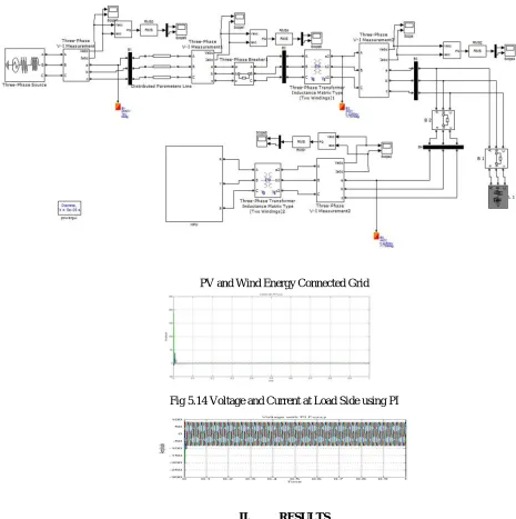
Model of PV and Wind Energy Connected Grid
[image:9.612.50.515.92.559.2]PV and Wind Energy Connected Grid
Fig 5.14 Voltage and Current at Load Side using PI
Fig 1.7 Voltage and Current at Load Side using PI Fuzzy
II. RESULTS
3-phase grid-connected rectifier/inverters are used widely in renewable, micro grid and electric power system applications.
PV and Wind Energy connected to power system controlled with Voltage source converter.This project investigates conventional vector control approaches for the power system-connected converters and analyzes the limitations associated with conventional vector control methods.And so, a Fuzzy –based PI vector control method is introduced.One of the main effects is that the associated low harmonics in current and voltage in Fuzzy PI as compared to PI.
III. CONCLUSION AND FUTURE SCOPE
Technology (IJRASET)
inexpensive variety of renewable energy and PV offers an added advantage over other renewable source because they produces no disturbance and require least maintenance.The combination of solar and wind power source provide a prudent sort of force generation.
IV. ACKNOWLEDGMENT
The authors would like to thank the commentators for their helpful comments which contributed to an improve the report.
REFERENCES
[1] Artificial Neural Networks for Control of a Grid-Connected Rectifier/Inverter Under Disturbance, Dynamic and Power Converter Switching Conditions Shuhui Li, Senior Member, IEEE, Michael Fairbank, Student Member, IEEE, Cameron Johnson, Donald C. Wunsch, Fellow, IEEE, Eduardo Alonso, and Julio L. Proaño IEEE TRANSACTIONS ON NEURAL NETWORKS AND LEARNING SYSTEMS, VOL. 25, NO. 4, APRIL 2014.
[2] Vector Control of a Grid-Connected Rectifier/Inverter Using an Artificial Neural
Network ShuhuiLi, Department of Electrical & Computer Engineering The University of Alabama Tuscaloosa,
[3]Grid Connected DC Distribution System for Efficient Integration of Sustainable EnergySources M.Elshaer, Member, AL 35487, USA email: [email protected] WCCI 2012 IEEE World Congress on Computational Intelligence June, 10-15, 2012 - Brisbane, Australia.
IEEE, A. Mohamed, Member, IEEE and O. Mohammed, Fellow, IEEE,2011.
[4] Soul-KI, Kim, Eung-Sang Kim, Jong-Bo Ahn “A hybrid system is formed by connecting the wind and solar systems together”.
[8] Andreas Poullikkas, “Implementation of distributed generation technologies in isolated Power systems,” Renewable and Sustainable Energy Reviews, Volume 11, Issue 1, Pages 30-56, January 2007.
[9] N Mohan, TM Underland, WP Robbins. “Power electronics: converters, applications, and design. 3rd ed. John Wiley & sons: 2003. [10] RW Erickson. “Fundamental of Power Electronics. Norwell, M :Kluwer; 1 ”.
[11] Jinhaeng Jang, Seokjae Choi, Byungcho Choi and Sungsoo Hong, "Average current mode control to improve current distributions in multi-module resonant dc-to-dc converters," Power Electronics and ECCE Asia (ICPE & ECCE), 2011 IEEE 8th International Conference, vol., no., pp.2312-2319, May 30 2011-June 3 2011. [12] Jaime Castelló Moreno, José M. Espí Huerta, Rafael García Gil and Sergio Alejandro González, “ Robust Predictive Current Control for Three-Phase Grid-Connected Inverters”. IEEE Transactions on Industrial Electronics, vol. 56, no. 6, June 2009.
[13] Juan C. Vasquez, Josep M. Guerrero, Alvaro Luna, Pedro Rodríguez and Remus Teodorescu, “ daptive Droop Control pplied to Voltage-Source Inverters Operating in Grid-Connected and Islanded Modes”. IEEE Transactions on Industrial Electronics, vol. 56, no. 10, October2009.
[14] Shuhui Li, Timothy A. Haskew, Yang-Ki Hong and Ling Xu, “Direct-current vector control of three-phase grid-connected rectifier–inverter,” Electric Power Systems Research, Volume 81, Issue 2, Pages 357-366, February 2011.
[15] Jiabing Hu, Lei Shang, Yikang He and Z. Q. Zhu, “Direct Active and Reactive Power Regulation of Grid-Connected DC/AC Converters Using Sliding Mode Control approach”. IEEE Transactions on Power Electronics, vol. 26, no. 1, January 2011