International Seminar on the Application of Science & Mathematics 2011 ISASM 2011
INTEGRATION OF H-SHAPED ELEMENT WITH
RECTANGULAR SLOT FOR BROADBAND
REFLECTARRAY ANTENNAS
Noor Ha fizah Sula iman1, (Muha mmad Yusof Is ma il2) 1,2
Radio Communications & Antenna Design Laboratory (RACAD), Faculty of Electrical and Electronic,
Universiti Tun Hussein Onn Malaysia, 86400 Parit Raja, Batu Pahat, Johor, Malaysia
1
[email protected] 2[email protected]
Printed reflectarray antenna is becoming rapid ly an attractive alternative to the more conventional parabolic reflector and phased array antennas due to its advantages such as lighter weight, low loss, easy to maintenance and less cost. However, the reflectarray antenna has a limited bandwidth performance due to its ele ments and spatial phase delays caused by the different lengths from the feed for each point on the wave front of the radiated beam. To enhance the static linear phase range and bandwidth performance of X band reflectarray antenna, this paper presents a novel technique by employing rectangular slot on H-shaped reflectarray antenna design. The numerical results based on Finite Integral Method demonstrate that the introduction of rectangular slot attached on H-shaped patch element is shown to increase the static linear phase range fro m 135.14° to 219.07°. Additionally analysis of the static phase range by using different widths (w)of rectangular slot investigated from 1.00 mm to 4.00 mm shows that 62.11 % imp rovement in phase range performance is achieved within the frequency variation of 10 GHz to 7.82 GHz which can be applied for tunable reflectarray antenna systems. The results obtained from this work show that by introducing variable rectangular slot on H-shaped patch reflectarray antenna the phase range is shown to be significantly improved which offers high potential for mu ltip le frequency antenna systems. Several para meters of reflectarray antenna such as reflection loss, reflection phase, bandwidth performance and static linear phase range are also discussed in this work.
Keywords: Reflectarray antenna; rectangular slot; static linear phase range; spatial phase delay; tunability antenna; bandwidth.
1. INTRODUCTION
candidate in wireless communications as it allows the expansion of systems capability. Bandwidth is one of the important parameters in antenna development especially with the increasing demands of data communications. However, there is one major shortcoming of the reflectarray which is narrow bandwidth behavior, primarily limited by its element and spatial path delays. Due to the bandwidth limitation, many researchers have proposed various techniques to enhance bandwidth performance [4]. In order to enhance the bandwidth performance, the thickness of the antenna substrate can be optimized with limitation in phase range performance [5]-[6]. In the reflectarray antenna, the phase range should be 360° at a given frequency in order to produce the suitable compensation to overcome the difference spatial phase delay. The path length from the feed to all patch elements is not uniform distributed. Because this limitation, a novel technique has proposed to enhance the static linear phase range by introducing rectangular slot on H-shaped element of reflectarray antenna design. Prelimanary analysis work shows that static phase range increase up to 217.07° by introducing rectangular slot on H-Shaped element. The simulation results are based on Finite Integral Method which has been performed by using commercially available Computer Software CST MWS.
2. ANALYSIS OF IMPORTANT PARAMETERS 2.1 Reflection Phase and Figure of Merit (FoM)
In order to analyze the bandwidth performance of H-Shaped element without and with rectangular slot, Figure of Merit (FoM) can be calculated from the reflection phase curve. The Figure of Merit (FoM) can be defined as the ratio of the change in the reflection phase to the change in the frequency (static phase range) [4] which indicates an aspect of performance for the bandwidth performance.
FoM
f
(°/MHz) (1)Where Δ¢ is the change in the reflection phase in degrees and Δf is the change in the resonant frequency in MHz of the reflectarray antenna and FoM is calculated in °/MHz. The incident signal illuminating from a feed antenna to the array elements scatter the incident field with the proper phase required in order to form a planar phase.
2.2 Reflection Loss and Bandwidth
International Seminar on the Application of Science & Mathematics 2011 ISASM 2011
3. METHODOLOGY
In this work, rectangular slot has been introduced on H-Shaped element of reflectarray antenna. The commercial electromagnetic simulation software CST MWS Studio has been used in order to simulate the proposed design.
[image:3.596.148.468.213.321.2]
(a) without rectangular slot (b) W=1.00 mm (c) W= 4.00mm Fig. 1. Configurat ion of H-Shaped ele ment
Fig. 1 shows the H-Shaped patch element of reflectarray antenna with embedded slot. In this work, rectangular slot has been introduced on the H-shaped element. Rectangular slot has been varied from 1.00mm to 4.00mm. The different width (w) of rectangular slot in the H-shaped element has been introduced in order to observe the relationship between linear static phase range, reflection loss and bandwidth performance.
4. RESULTS AND ANALYSIS
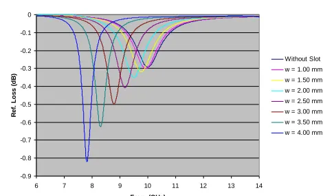
Analysis of H-Shaped element without and with rectangular slot configurations has been carried out using commercially available computer model of CST Microwave Studio (CST MWS). Fig. 2 shows the reflection loss plots for an H-Shaped of reflectarray antenna embedded with variable rectangular slot configurations.
Reflection Loss for variable slot
-0.9 -0.8 -0.7 -0.6 -0.5 -0.4 -0.3 -0.2 -0.1 0
6 7 8 9 10 11 12 13 14
Freq. (GHz)
R
e
f.
Lo
s
s
(
dB
)
[image:3.596.190.425.506.649.2]Without Slot w = 1.00 mm w = 1.50 mm w = 2.00 mm w = 2.50 mm w = 3.00 mm w = 3.50 mm w = 4.00 mm
Fig. 2. Reflection loss curve for without and with rectangular slot
element, the proposed design has advantages of providing multiple frequencies for reconfigurable antenna systems. The frequency can be easily adjusted by changing the rectangular slot intergrated with H-Shaped element which offers tunabily from 10 GHz to 7.82GHz. The simulated results obtained from CST MWS have beem summarized in Table 1.
Table 1. Summary of results Width,
w (slot)
Frequency (GHz)
Reflection Loss (dB)
Surface Current (A/m) Without
Slot 10 0.292
171
W = 1.0 9.928 0.300 162
W = 1.5 9.768 0.318 148
W = 2.0 9.504 0.350 138
W = 2.5 9.184 0.408 127
W = 3.0 8.792 0.499 118
W = 3.5 8.304 0.625 106
W = 4.0 7.824 0.819 99
Table 1 shows the summary result effect for the resonant frequency and reflection loss performance by introducing rectangular slot in H-shaped element. It can be observed that the variation of the resonant frequency and the reflection loss is increased from 0.292 dB to 0.819 dB as the width (W) of rectangular slot increased from 1.00 mm to 4.00 mm. The results are caused by the effect the introduction rectangular slot on H-Shaped element reflectarray antenna which affects the surface current and the electrical dimension of the H-Shaped element. The variation in the surface current distribution from 171 A/m to 99 A/m caused a variation the reflection loss performance.
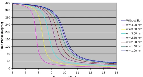
Reflection Phase
0 40 80 120 160 200 240 280 320 360
6 7 8 9 10 11 12 13 14
Frequency (GHz)
R
e
f.
P
h
a
s
e
(
D
e
g
re
e
) Without Slot
[image:4.596.188.434.523.656.2]w = 4.00 mm w = 3.50 mm w = 3.00 mm w = 2.50 mm w = 2.00 mm w = 1.50 mm w = 1.00 mm
International Seminar on the Application of Science & Mathematics 2011 ISASM 2011
Fig. 3 shows the reflection phase curve by varying rectangular slot on the patch element from 1.00mm to 4.00mm. It can be observed that the slope (w =1.00mm) has much gentler as compared slope (w =4.00mm). It can be seen that by employing rectangular slot (w =4.00 mm) the static phase range can be increased. All the simulated results have been summarized in the Table II.
Table II. Su mmary o f results for bandwidth and static phase range performance
Width, w (slot)
Frequency (GHz)
Bandwidth, 10% BW
(MHz)
Bandwidth, 20% BW
(MHz)
Figure of Merit,
FoM (°/MHz)
Static Phase Range (Δ¢) Without
Slot 10 367.1 547.2 0.207 135.14
w = 1.0 9.928 365.1 546.1 0.209 142.10
w = 1.5 9.768 362.4 544.5 0.212 150.47
w = 2.0 9.504 357.1 537.3 0.215 158.61
w = 2.5 9.184 351.7 526.7 0.220 169.19
w = 3.0 8.792 340.4 516.2 0.228 175.45
w = 3.5 8.304 328.8 489.3 0.231 196.70
w = 4.0 7.824 317.1 471.5 0.241 219.07
As depicted in Table II, it can be seen that the H-shaped with rectangular slot offers 0.241 °/MHz FoM with 219.07° of static phase range compared to without rectangular slot which gives a minimum figure of merit of 0.207 °/MHz with 135.14° of static phase range. By introducing rectangular slot on H-Shaped element of reflectarray antenna, the static phase range is shown to be increased from 135.14° to 219.07° whereas FoM is observed to increase gradually from 0.207MHz to 0.241MHz. It can be observed that the FoM is directly proportional to the static phase range performance. It can be seen that there is a trade off between static phase range and bandwidth performance.
5. CONCLUSION
(VOT 0718), Ministry of Higher Education, Malaysia. We would like to thank the staff of Radio Communications and Antenna Design (RACAD) Laboratory of Universiti Tun Hussein Onn Malaysia (UTHM) for the technical support.
REFERENCES
[1] M.Y.Ismail, M.F. M. Shukri, Z. Zakaria, A.F.M.Zain, M.F.L. Abdullah and M.Ubin (2009). “Investigation of Static Phasing Distribution Characteristics of Passive Reflectarray Antenna Elements”, PIERS Proceedings, Moscow Russia. [2] J. Huang and J. Encinar. (2008) Reflectarray Antenna, IEEE Antennas and
Propagation Society, Wiley.
[3] F. Yang, and Y.R Samii (2005).“Patch Antennas with Switchable Slots (PASS) in Wireless Communications: Concepts, Design and Applications”, IEEE
Antennas and Propagation Magazine, Vol. 47, No. 2
[4] M.Y.Ismail and M.Inam. (2010) “Analysis of Design Optimization of Bandwidth and Loss Performance of Reflectarray Antennas Based on Material Properties,” Modern Applied Science J. CCSE. Vol. 4, No.1. pp 28-35,
[5] D. M. Pozar, S. D. Targonski, H. D. Syrigos.(1997) “Design Of Millimeter Wave Microstripreflectarrays”; IEEE Trans. on Antennas andPropag., vol. 45, no. 2;; pp. 287- 296.
[6] K. Y. Sze, L. Shafai (1998) “Analysis Of Phase Variation Due To Varying Patch Length In A Microstrip Reflectarray”, IEEE Antennas and Propag.
Society InternationalSymp.
[7] M. Clemens and T. Weiland, (2001). “Discrete Electromagnetism with the Finite Integration Technique”, Progress In Electromagnetics Research, PIER