© 2017, IRJET | Impact Factor value: 5.181 | ISO 9001:2008 Certified Journal | Page 1697
A Review of Node Deployment Techniques in Wireless Sensor Network
Er. Vaishyampayan Jain
1, Er. Tarun Kumar
21
M.Tech. Student, Computer Science & Engineering,
Geeta Institute of Management & Technology,
Kanipla, Kurukshetra, Haryana, India
2
Assistant Professor, Computer Science & Engineering,
Geeta Institute of Management & Technology,
Kanipla, Kurukshetra, Haryana, India
---***---Abstract -
Sensor is an important part of an automaticsystem. Wireless Sensor Network (WSN) is a system consisting of large number of Sensor Nodes (SNs) geographically distributed in the region to be monitored. Placement of SNs in the region to be monitored is the major factor that determines the life, coverage area and connectivity of WSN. Because of the limited sensing range of SN, most of the events cannot be sensed from distant locations. Thus, to achieve reliable connectivity, maximum network life and to achieve maximum coverage with their minimum count required numerous schemes have been proposed by the researchers for deployment of Mobile Sensor Nodes (MSNs). In this paper, authors have done a comparative analysis of various sensor node deployment techniques for wireless sensor network.
Key Words:Wireless sensor network, Node deployment techniques, Maximum coverage, Network life, Energy
1. INTRODUCTION
Sensor is a vital part in an automatic system. These sensors could be natural or artificial. Wireless sensor network (WSN) consists of large number of small, low power, low cost sensor nodes with limited memory, computational, and communication resources and a Base Station. These nodes continuously monitor environmental conditions and collect detailed information about the physical environment in which they are installed, and then transmits the collected data to the BS [1]. SNs keep track of the physical changes that take place in their vicinity. Challenges in monitoring natural and artificial environments for control and automation have attracted researchers to work in the field of WSNs. The life, coverage area and connectivity of WSN [2] widely depend on the placement of SNs in deployment area. WSN is applicable for disaster handling, military surveillance, monitoring of habitat, tracking target, monitoring health of structures, agriculture, intrusion detection and medical monitoring applications [3]. Most of the events cannot be sensed from distant locations as SN has limited sensing range (rs), this require SN to be placed at a
distance d, (d≤rs) from probable location of occurrence of
event.
Various schemes have been proposed by the researchers for deployment of Mobile Sensor Nodes (MSNs), which aims at
achieving reliable connectivity, maximum network life and minimizing the energy required by MSNs to spread uniformly within the deployment region in order to achieve maximum coverage with their minimum count required [4]. WSN has an advantage of being operated unattended in the environment where continuous human monitoring is either risky, inefficient or infeasible. Therefore, WSNs are mostly deployed in hostile environments like volcanoes, flooded regions, deep oceans, etc. Sensor nodes run on batteries and once nodes are deployed their batteries cannot be recharged, so they have short lifespan. Efforts are made to enhance its efficiency. Installing SNs is one of the major factors that determines the life and effectiveness of any WSN. Deployment can be classified as manual and random. Among this random ssensor node can be deployed by dropping from a plane, throwing by a catapult, placing in factories, and placing one by one either by a human or a robot [5]. A sparse deployment of sensor nodes is expected in underwater and volcanic data collection contrary to a dense deployment of sensor nodes in a terrestrial WSNs.
Initially SNs are deployed by dropping from flying machine (helicopter, airplane, etc.) over the deployment area. For this purpose, low cost parachutes are preferably used to ensure safe landing of SNs. Base Station (BS) is mostly placed outside the deployment area and is considered to have sufficient resources in terms of energy and bandwidth to directly transmit instructions to any SN in the deployment area. Every SN is considered to have limited communication range (rc) and rs. SN can be mounted on a mobile device to
change its physical position in order to adapt the changes required in the network. Deployment can be homogeneous (consisting of SNs with same configuration and capability) or heterogeneous (consisting of SNs with different configurations and capabilities).
In the section 2, different sensor node deployment policies for wireless sensor network have been discussed in detail. Section 3 explores the comparative analysis of sensor node deployment techniques discussed in section 2. Conclusion and future scope are given in section 4.
2. SENSOR NODE DEPLOYMENT TECHNIQUES
© 2017, IRJET | Impact Factor value: 5.181 | ISO 9001:2008 Certified Journal | Page 1698 deployment. Out-door deployment is concerned with
placement of SNs in open/exposed environments under more violent climatic conditions where large area is to be covered (that may range between front yard lawn of few square meters to dense forests of thousands of square Km.). Considering the area of candidate's region, the strategy for placement of SNs is chosen. Random scattering of SNs is commonly used deployment strategy for larger open area where as deterministic SN placement strategy may be used for small open area deployments. Consider the common case of forest fire in mountain region of India. Since this is the scenario of large-open area, and random scattering strategy is deployed to achieve blanket type pattern over the entire candidate region to detect forest fire.
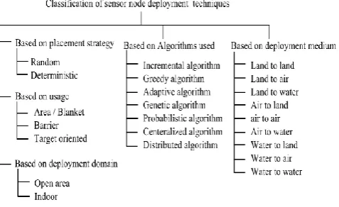
[image:2.595.43.282.381.527.2]Another case of enemy camp monitoring comes under the category of target oriented deployment and for this deterministic node placement strategy may be applied using land to land or air to land as medium of deployment. Classification of techniques of sensor node deployment, are based on the placement strategies, deployment domain, usage, algorithms used and medium of deployment and are summarized in Figure 1.
Fig -1: Classification of sensor node deployment techniques
2.1 Potential Field Based Method
Authors in [6] proposed a Potential Field based method (PFM) for uniformly distributing MSNs in deployment area. The basis of PFM was the real time environmental conditions of deployment area like obstacles (in the form of buildings, water bodies, etc.). It is mainly concerned with the uniform distribution of sensor nodes within the target area. PFM incorporated the characteristic of self-deployment, i.e., all the MSNs are initially spread in very small and they relocate themselves using some method to maximize the coverage in deployment area in which it assumes that probably there is a field that exerts a force of repulsion on MSNs from obstacles and other MSNs. The MSNs distribute themselves in the considered area according to this repulsive power. MSNs move in the direction that is the net result of vector sum of all the forces exerted on particular MSN. Besides the fact that
PFM provides a simple approach for distribution of MSNs within deployment area but due to oscillations and connectivity with BS the large movements of MSNs is also not specified. Even due to cascading effect the unbalancing of load is also not considered.
2.2 Virtual Force Based Scheme
Virtual Force Method (VFM) is a cluster based approach [7], in which randomly spread MSNs forms a cluster based on their random physical locations. All MSNs are managed by cluster head (CH) i.e the elected MSN only. VFM is evolved from PFM [6] and method of packing equal circles in a square. Each of the deployed SNs exerts a force on other SNs. depending on the distance of the nodes the force exerted by SNs can be attractive or repulsive. A repulsive force is applied on both MSNs to increase the coverage if they are very close to each other (distance being less than predefined threshold). Contrary to this, an attractive force is applied on both of them in order to bring them close if they are far apart from each other (distance being more than predefined threshold). This is done to uniformly spread the MSNs in the deployment area and to maintain connectivity, while obstacles exerts force of repulsion and force of attraction is exerted by regions with low density of MSNs.
Since the attraction and repulsion consumes large amount of time and energy so these are not physically performed but are logically performed by the CHs and final destination is decided for each MSN. Even to reduce the network traffic VFM uses MSNs to transmit information in binary form (yes or no) to their CHs on detection of event and detailed information is only transmitted when asked for. If any target MSN (St) is detected by MSNs in any cluster, they inform their detection to the CH using binary signals (yes or no). Based on these signals, CH determines the candidate MSNs (that can participate in positioning St). CH then ask candidate MSNs to get detailed information about St.
In VFM MSN movements are effectively reduced by performing various logical movements at CHs before final movements of MSNs, but still connectivity with BS is not guaranteed and no concern is given to cascading effect as in PFM.
2.3 Connectivity Preserved Virtual Force
© 2017, IRJET | Impact Factor value: 5.181 | ISO 9001:2008 Certified Journal | Page 1699 moving towards the destination MSNs regularly check for
nearest neighboring MSN (MSN closer to the destination) and on finding such neighbor, MSN stops for a certain interval in a hope that the neighboring MSN will get connected to the destination node to form a communication path. This process is repeated until all the MSNs are connected to destination. In addition to using traditional VFM for deploying MSNs within the deployment area, CPVF focuses on ensuring the connectivity of every randomly spread MSNs in deployment area. This is achieved by moving all the MSNs in straight line towards the BS to get connected. While moving in straight line and to deal with obstacles MSNs uses BUG2 algorithm and Lazy movement strategy to minimize their movement.
After getting connected to BS, another phase starts to expand the coverage of network while maintaining connectivity. This phase uses VFM. CPVF guarantees network connectivity along with reduced MSN movements by incorporating lazy movement strategy, but 100% coverage is not achieved and cascading effect is still not considered.
2.4 FLOOR Based Scheme
FLOOR based scheme is an extended version of Connectivity Preserved Virtual Force Method (CPVF) [8]. Similar to CPVF, this scheme uses BUG2 algorithm and Lazy Movement strategy to deal with obstacles and to minimize MSN movement respectively. After random dispersion of MSNs in deployment area, they start moving to their nearest Floor lines that are separated by a distance d=2*rs. MSNs intimate
BS after getting connected, and BS sends the IDs of all their ancestors to them as an acknowledgement. The aim of this phase is to find out the MSNs that can be moved to expand the coverage without splitting the network. For becoming movable, MSNs attempt to search new parents for their children MSNs, so that the children remain connected. Also the area covered by them at current location is determined by checking the locations of their neighbors’. They move if area covered is less than certain threshold value. The MSN is chosen as Floor-Head that has least value of x-coordinate on particular floor. FH is responsible for keeping information about all the MSNs on that floor. MSNs also check for the uncovered locations by checking the position of neighboring MSNs on the same floor and on adjacent floors, so that a movable MSN can be called to cover the region. After the recognition of all movable MSNs they are moved to expand the coverage whereas non-movable MSNs searches for the uncovered regions and identifies the point where movable MSN can be placed to effectively cover that region. 100% coverage is not achieved because of uncovered Patches left between rs of SNs on adjacent floor lines. FLOOR based
scheme further minimized MSN movements, but load unbalancing due to cascading effect is not considered even in this scheme.
2.5 Obstacle Resistant Robot Deployment algorithm (ORRD)
Authors in [9] present an obstacle resistant robot assisted deployment scheme that employs a mobile robot to carry SNs and place them in desired locations when a robot traverses the deployment area from east to west and north to south, thus forming a snake like path for placing the SNs. In ORRD the robot takes basic moves based on its current state and deploys a SN at the end of every move and same process is repeated.
2.6 Uniform Airdrop Deployment Method (UAD)
UAD is a SN deployment scheme that utilizes the gliding property of parachute to uniformly distribute SNs dropped from hovering Helicopter in the Deployment region (D). In UAD [10] authors consider that helicopter hovers above the center of circular deployment region with radius R at specific altitude H and parachute mounted SNs are dropped from that point neglecting the effect of wind on SNs while dropping.
To control the dropping behavior of parachute between gliding and falling states, an additional device is integrated with it. While dropping, vertical velocity of SNs i.e. Vz is considered as constant throughout its overall journey before hitting the ground. The horizontal velocity Vxy is accounted
for SNs gliding state only and it is 0 during its falling state. Direction of gliding θ for particular SN also remains same throughout its ride once it is determined randomly. Besides the effectiveness of UAD for uniform deployment of static SNs over large deployment region using aerial vehicles the scheme lacks in considering the effect of wind and terrain of deployment region. Moreover, in UAD large amount of energy is consumed by the use of motor driven propeller for horizontal gliding movement.
2.7 Fault Revoking and Homogeneous Distribution (FRHD)
© 2017, IRJET | Impact Factor value: 5.181 | ISO 9001:2008 Certified Journal | Page 1700 the subdivision to which they belong and send "hello" packet
to the BS to claim the ownership of subdivision. The first MSN to claim is elected as the owner of that region else it is granted the ownership of nearest unoccupied subdivision and instructed to move to that subdivision. After associating MSNs with subdivisions MSNs checks its sub division for the availability of sufficient number navg of SSNs. If the available
SSNs in any subdivision are less than navg, then MSNs in
depriving subdivision asks the neighboring MSNs to fetch extra SSNs in their territory to the common boundary from where it can pick SSN and place it in appropriate location. If neighboring subdivisions don't have extra SSNs then FSNs are requested to fetch extra SSNs from corresponding subdivisions to the deprived subdivisions thus performing homogeneous distribution.
FRHD attempts to achieve uniform SN distribution by ensuring sufficient number of SNs within a subdivision but position of SNs within subdivision is not specified, moreover FRHD uses MSNs for relocation of SNs which seems to be unreal for uneven terrains.
2.8 SEEDS: Scalable Energy Efficient Deployment Scheme for homogeneous wireless sensor networks
Another scalable deployment scheme was proposed by Munish et. al. [15]. It was designed to maximize the area coverage by placing minimum number of sensor nodes and attaining complete connectivity with minimum relocation of SNs. It is similar to DDS [14] as same relation between communication and sensing range is used by both. Although both the models are designed to achieve blanket coverage over large open-area candidate region where random scattering of SNs from air land is done in initial phase of deployment. Yet, it is different from DDS in terms of claimed scalability and distributed algorithm used by it to concurrently move MSNs to appropriate desired locations within a candidate region. It also consists of obstacle handing algorithm as its integral part. Base Station broadcasts the complete list of precomputed Desired Locations (DLs) to randomly scattered MSNs, and then is sorting is done on the basis of their Euclidean distance from each DL. MSNs then start moving (in the order specified by the sorted list) towards each DL until unoccupied DL is achieved. Placed MSNs broadcast STOP message after regular intervals in order to stop MSNs arriving to that DL. MSNs stops, it sorts the remaining list and start moving again in the same pattern.
Drawback of this model is that the size of DL list proportionally increases with the area of candidate region. This not only increases the size of broadcast packet but also the computation overhead on MSNs as they repeatedly have to sort the list based on their current location. Similar to DDL this method is also not scalable.
3. ANALYSIS
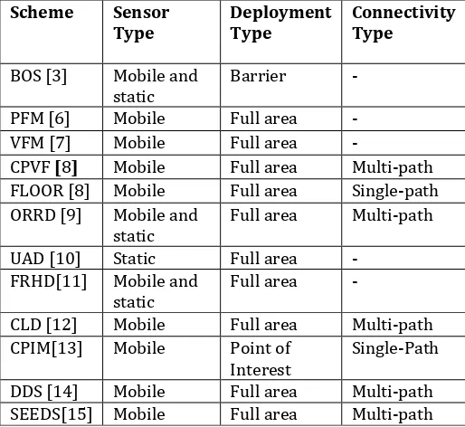
[image:4.595.305.562.206.442.2]Based on the various schemes discussed in the previous section comparative analysis of different node deployment schemes for wireless sensor network on the relevant parameters is summarized in the table given below
:
Table -1: Comparative analysis of deployment schemes.
Scheme Sensor
Type Deployment Type Connectivity Type
BOS [3] Mobile and
static Barrier - PFM [6] Mobile Full area - VFM [7] Mobile Full area -
CPVF [8] Mobile Full area Multi-path FLOOR [8] Mobile Full area Single-path ORRD [9] Mobile and
static Full area Multi-path UAD [10] Static Full area -
FRHD[11] Mobile and
static Full area -
CLD [12] Mobile Full area Multi-path CPIM[13] Mobile Point of
Interest Single-Path DDS [14] Mobile Full area Multi-path SEEDS[15] Mobile Full area Multi-path
According to Table 1, most of the deployment schemes use mobile robots (i.e., MSNs) most of the deployment schemes use mobile robots (i.e., MSNs) as they can be relocated after initial random- droppings from air. Even after regular attempts by various researchers to minimize MSN movements, it still consumes the major part of energy. Moreover, MSNs are more sophisticated devices which have limited mobility and accessibility for varied terrains.
Table -2: Comparative analysis of deployment schemes.
Sch-
eme Connec-tivity guaran-teed
Cas-cading
effect resistant
Scal-
able tacle Obs- resis-tant
Terrain indep-endent
BOS[3] No - Yes - -
PFM[6] No No Yes Yes No
VFM[7] No No Yes Yes No
CPVF
[8] Yes No Yes Yes No
FLOOR
[8] Yes No Yes Yes No
ORRD
[9] - No No Yes No
UAD
[image:4.595.303.565.582.780.2]© 2017, IRJET | Impact Factor value: 5.181 | ISO 9001:2008 Certified Journal | Page 1701 FRHD
[11] - No Yes No No
CLD
[12] Yes Yes No - No
CPIM
[13] Yes No - No No
DDS
[14] Yes No No No No
SEEDS
[15] Yes No No Yes No
Use of MSNs may be more suitable for PoI and Barrier Deployment than full area coverage. According to Table 2, few schemes including CPVF, FLOOR, DDS, CLD and CPIM guarantee the connectivity of SNs with BS and enhances the network reliability, where as other schemes considers only uniform spreading of SNs within deployment region. Due to cascading effect there is uneven depletion of energy. This effect also degrades the lifetime of WSN as SNs closer to sink consumes more energy to form prime communication link with sink. Because of the impact on WSNs lifetime Most of the schemes have ignored cascading effect in their discussions but CLD is the only scheme to provide the solution to cascading effect, but the solution is restricted to small area deployments and is not scalable.
Scalability is an important parameter, as it generalizes the scheme for any size of deployment region and keeps it independent of other variables. Most of the schemes except DDS, CLD and ORRD are scalable.
Algorithms are included in few schemes (PFM, VFM, CPVF, FLOOR and ORRD) to deal with obstacles in deployment region, which is more realistic, while other schemes assume deployment region to be plain ground without obstacles. However, none considers bushes, shrubs etc as obstacles of external environments. Deployment regions includes unreachable, hazardous environments with uneven terrain. Indulgence of ground MSNs makes the scheme more dependent on terrain of deployment region. So most of the schemes (except UAD and ADR) employing MSNs are dependent on terrain.
Moreover, most of the schemes use aerial dropping method to randomly scatter SNs within deployment region without considering the impact of regional wind on the droppings.
4. CONCLUSIONS
The performance of the wireless sensor network depends mainly on the positioning of the sensor nodes in WSN. In this paper, authors have analyzed the performance of various sensor node deployment schemes on the scale of connectivity, scalability, obstacle resistance, terrain independence and cascading effect resistance. As a future scope, authors have planned to propose an effective sensor deployment scheme for wireless sensor network.
REFERENCES
[1] D. Agrawal and Q.A. Zeng, “Introduction to wireless and
mobile systems”, Cengage Learning, 2010.
[2] Amitabha Ghosh and Sajal K Das, "Coverage and
connectivity issues in wireless sensor networks”, A survey," Pervasive and Mobile Computing, vol. 4, no. 3, pp. 303-334, 2008.
[3] Zhi Sun, "Border sense: border patrol through advanced
wireless sensor networks", Ad Hoc Networks, vol. 9, no. 3, pp. 468-477, May 2011.
[4] Chee-Yee Chong and Srikanta P Kumar, "Sensor
networks: evolution, opportunities, and challenges", in Proceedings of the IEEE, 2003, pp. 1247-1256.
[5] Gurkan Tuna, TarikVeli Mumcu, Kayhan Gulez, Vehbi
Cagri Gungor, and Hayrettin Erturk, "Unmanned aerial vehicle-aided wireless sensor network deployment system for post-disaster monitoring", Emerging Intelligent Computing Technology and Applications, vol. 304, pp. 298-305, Unmanned Aerial Vehicle-Aided Wireless Sensor Network Deployment System for Post-disaster Monitoring 2012.
[6] Andrew and Matari'c, Maja J and Sukhatme, Gaurav S
Howard, "Mobile sensor network deployment using potential fields”, A Distributed, Scalable Solution to the Area Coverage Problem", Distributed autonomous robotic systems, pp. 299-308, 2002.
[7] Yi Zou and Krishnendu Chakrabarty, "Sensor
deployment and target localization based on virtual forces", in INFOCOM 2003. Twenty-Second Annual Joint Conference of the IEEE Computer and Communications. IEEE Societies, San Francisco, 2003, pp. 1293-1303.
[8] Nojeong Heo and Pramod K Varshney, "A distributed self
spreading algorithm for mobile wireless sensor networks", in Wireless Communications and Networking, 2003. WCNC 2003. 2003 IEEE, New Orleans, LA, USA, 2003, pp. 1597-1602.
[9] Chih-Yung Chang, Yu-Chieh Chen, and Hsu-Ruey Chang,
"Obstacle-resistant deployment algorithms for wireless sensor networks", IEEE Transactions on Vehicular Technology, vol. 58, no. 6, pp. 2925-2941, 2009.
[10] Yoshiaki Taniguchi, Tomoya Kitani, and Kenji Leibnitz,
"A uniform airdrop deployment method for large-scale wireless sensor networks", International Journal of Sensor Networks, Inderscience, vol. 9, no. 3/4, pp. 182-191, 2011.
[11] D Prasad, M Gupta, and R. B. Patel, "Framework for fault
revoking and homogeneous distribution of randomly deployed sensor nodes in wireless sensor networks", International Journal of Computer Science Issues (IJCSI), vol. 8, no. 2, pp. 189–197, 2011.
[12] Y-S Yen, Sheng Hong, R-S Chang, and H-C Chao,
"Controlled deployments for wireless sensor networks", IET communications, vol. 3, no. 5, pp. 82--829, 2009.
[13] Milan Erdelj, Tahiry Razafindralambo, and David
© 2017, IRJET | Impact Factor value: 5.181 | ISO 9001:2008 Certified Journal | Page 1702 sensors", IEEE Transactions on Parallel and Distributed
Systems, vol. 24, no. 1, pp. 32-43, 2013.
[14] Ajay Kumar, Vikrant Sharma, and D Prasad, "Distributed
deployment scheme for homogeneous distribution of randomly deployed mobile sensor nodes in wireless sensor networks", International Journal of Advanced Computer Science and Applications, vol. 4, no. 4, pp. 139-146, 2013.
[15] Munish Gupta, C, Rama Krishna, and D Prasad, "SEEDS: