BIROn - Birkbeck Institutional Research Online
Al-Nima, R. and Han, Tingting and Chen, Taolue (2019) Road tracking using
deep reinforcement learning for self-driving car applications. In: The 11th
International Conference on Computer Recognition Systems, 20-22 May
2019, Polanica-Zdroj, Poland. (In Press)
Downloaded from:
Usage Guidelines:
Please refer to usage guidelines at
or alternatively
Road Tracking Using Deep Reinforcement
Learning for Self-Driving Car Applications
?Raid Rafi Omar Al-Nima1,2, Tingting Han1, and Taolue Chen1
1
DCSIS, Birkbeck, University of London
2 Technical Engineering College of Mosul, Northern Technical University, Iraq
Abstract. Deep reinforcement learning has received wide attentions
re-cently. It combines deep learning with reinforcement learning and shows to be able to solve unprecedented challenging tasks. This paper proposes an efficient approach based on deep reinforcement learning to tackle the road tracking problem arisen from self-driving car applications. We pro-pose a new neural network which collects input states from forward car facing views and produces suitable road tracking actions. The actions are derived from encoding the tracking directions and movements. We perform extensive experiments and demonstrate the efficacy of our ap-proach. In particular, our approach has achieved 93.94% driving accu-racy, outperforming the state-of-the-art approaches in literature.
Keywords: Road Tracking, Deep Reinforcement Learning, Self-Driving
1
Introduction
Road tracking is one of the most challenging tasks emerged from key applications such as autonomous driving. It aims to automatically guide a car through the correct track without crashing other cars or objects. Reinforcement learning (RL), in a nutshell, is concerned with an agent interacting with the environment, learning an optimal policy, by trial and error, for sequential decision making problems. The combination of deep neural networks and reinforcement learning gives rise to deep reinforcement learning (deep RL, DRL). We hypothesise that DRL can be one of the most promising methods to address the road tracking challenge, and this paper reports our approaches and results to apply DRL to accomplish some typical tasks in road tracking.
One of the primary tasks in road tracking is to track objects, e.g., walk-ing people, buildwalk-ings, cars, etc [1–4]. Other trackwalk-ing tasks include trackwalk-ing and controlling velocity [5], tracking periodic gene repressilator [6], tracking single and double pendulum [7], and tracking maximum powers for wind speed conver-sion systems [8]. Applying DRL techniques to road tracking has been reported,
but has not been explored thoroughly. For instance, Perotet al.[9] investigated
?T. Chen is supported by EPSRC grant (EP/P00430X/1), ARC Discovery Project
tracking roads of a driving car where DRL was used. The main problem thereof is that the driving car oscillates around the main road track. This is due to the selected reward in the study, where it utilised the oriented angle of the road
with the car speed. More generally, Yunet al.[10, 11] proposed an action-decision
network (ADNet) to track objects (not necessarily for road tracking purposes), where a pre-trained Convolutional Neural Network (CNN) was firstly employed followed by the reinforcement learning.
Our work contributes to this area by suggesting an effective road tracking procedure based on the deep reinforcement learning and by employing notions from Markov Decision Processes, where states are used as inputs; rewards are utilised to evaluate the tracking policy and actions are predicted to provide new states. Effective coding for various road tracking possibilities of actions has been considered such as turning to the left or right and recognising crossing object(s). The established codes have been used as regression information in the proposed DRL to train the neural network and maintain the actions.
Related work. Due to space restriction, we can only discuss related work briefly, focusing on those pertinent to applying reinforcement learning for tracking ob-jects purpose. For tracking obob-jects, Grigore and Grigore [1] proposed a tracking system controller by using a recurrent neural network combined with the rein-forcement learning. Cohen and Pavlovic [2] suggested an effective and vigorous real-time tracker, which utilised reinforcement learning and was applied to track-ing personal faces. Liu and Su proposed an object tracktrack-ing method to determine
the features of the tracking object [3]. Supanˇciˇc and Ramanan constructed a
learning policy for tracking objects. The reinforcement learning was applied to video streams to provide on-line decision [4].
2
Modelling
In this section, we address various essential issues to model the road tracking, such as how to identify road crossing object(s), how to encode different track-ing directions, and how to design the deep reinforcement learntrack-ing network to determine the next action, etc.
The database. Our research is based on the SYNTHIA-SEQS-05 database [12]. Video sequences were recorded and saved, from which one extracted front, rear, left and right view road images around the car for both right and left steering cars. Each view covers a range of angle up to 100 degrees. As a result, a large
number of simulated image frames were provided, each has a resolution of 760×
1,280×3 pixel.
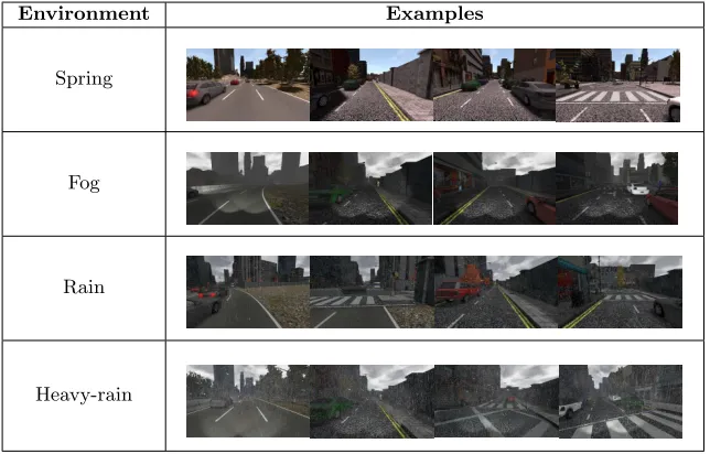
The images were taken in four different environments: (1) clear environment in spring, (2) fog, (3) rain and (4) heavy-rain environment. Examples from the
four databases are given in Table 1. In our study, we look atforward view road
Environment Examples
Spring
Fog
Rain
[image:4.612.146.468.115.321.2]Heavy-rain
Table 1: Examples of the four employed environments
2.1 Road tracking
To differentiate the main objects on the road, the databases provide specific colours for certain objects in the images, e.g., sky is grey, buildings are brown, roads are purple, side walks are blue and road markings are green. Overall, the purple and green colours refer to the allowed driving regions.
Based on the images, we further divide each view (image) into a safety zone and a danger zone. If objects are spotted in the safety zone the car can keep moving, as the zone is further away, allowing ample time to stop or slow down if necessary. The danger zone is the area that a car must stop if any objects are recognised. Such zones can be found in Fig. 1.
Danger zone Safety
zone Anchor
point
Moving Base
Slopping lines
Fig. 1: The suggested front view road tracking zones, lines and anchor point
To determine a safety zone or a danger zone, a virtual triangle and trapezoid are drawn. The base of the tri-angle and trapezoid moves in the road direction, and the crossing lines slope toward the tracking direction. The height of the triangle (and the trapezoid) is two thirds of the image. The top one third of the trapezoid is the safety zone and the bottom two thirds is the danger zone. The shared point of the triangle and the trapezoid is
called an anchor point. It denotes the road tracking direction by following the
By drawing the virtual triangle in the trapezoid area we can divide the region into left, right and centre region, with which the direction of any crossing objects can be specified. The car can, for instance, avoid an object crossing from the left side by moving to the right, if the space is empty there. If objects are identified from both sides in the danger zone, then the car has to stop.
2.2 Actions codes
At each decision point, a car can take one of the following actions: straight on, turn left or right, reverse and stop. In our work, we use a 5-digit binary number to encode each action, see Table 2.
Action sign Binary
code
Equivalent
decimal code Description
Straightforward 01110 14 follow the straight track
Turn left 11100 28 follow the track to the left
Turn right 00111 7 follow the track to the right
Stop 00000 0 object(s) identified from both sides
[image:5.612.134.484.260.342.2]Backwards 11111 -31 reverse
Table 2: The road tracking actions with their suggested codes and descriptions
When a crossing object is detected, it will change the code from that side with a “0”. For instance, a car is moving forward with action 01110, then an object appears in the danger zone from left, the action code becomes 00111, indicating that the car should turn right to avoid the object. If another object appears from the right, the code will be 00110 and the car will have to stop. A car has to stop as long as there are no three consecutive 1’s. We model all such cases as 00000 to reduce the number of coding values. Fig. 2 shows various coding cases. The cases in the red dashed box are all coded as 00000.
The binary codes can be converted to desired equivalent decimal codes in the standard way. The only exception is the backward direction, where a negative sign (-) is added to refer to the reverse movement. The reverse action will only be considered if the car is out of the track. The decimal codes are used in the regression layer of the proposed network as will be explained later.
2.3 Proposed DRL-RT
In this section, we present the neural network (NN) used in the Deep Reinforce-ment Learning framework for Road Tracking (DRL-RT), which consists of eight layers: two convolution layers, two Rectified Linear Unit (ReLU) layers, a pool-ing layer, a fully connected layer, a regression layer and a classification layer. Theoretical explanations of the main deep NN layers can be found in [13]. Fig. 3 depicts the proposed DRL-RT network.
We now elaborate the NN architecture as follows: (a)The input of the NN is an image of a car facing view which is considered as the current state. The
0 0
0 0 0
1 1
1 0 0
1 1
1
0 0
(a) (b)
1 1
1 1 1
1
1 1
0 0
(c) (d)
0 1
0 1 0
1 1
0 0 0
(e) (f)
1 0
0 0 0
1 0
0 1 0
(g) (h)
0 0
0 1 0
0 1
0 0 0
(i) (j) (k)
0 0
0 0 0
[image:6.612.148.461.111.268.2]Danger zone Safety zone One crossing object Two crossing objects Two crossing objects Three crossing objects
Fig. 2: Segmented images for road tracking: (a) straightforward, (b) turning left, (c) turning right, (d) reverse or backward, (e-g) stopping action because of a single crossing object, (h-j) stopping action because of two crossing objects and (k) stopping action because of three crossing objects
Input State Action New State Conv
1 ReLU1 Conv 2 ReLU2
Pool (Max)
FC Reg. Class. Reward
Fig. 3: The main design of the proposed DRL-RT. It consists of two convolution layers, two ReLU layers, a pooling layer, a fully connected layer, a regression layer and a classification layer
the training. (b) The first layer is a convolution layer which consists of 5 filters,
each of which has a filter size of 10×10 pixels. This layer is to extract the main
features of the input image. This is followed by a ReLU layer which removes the negative values and maintains the positive values of the previous layer. (c) The third layer is again a convolution layer, consisting of 5 filters, each of which
has a filter size of 5×5 pixels. This layer extracts more features from the input
images. A ReLU layer is employed, which rectifies the negative values. We note that it has empirically been established that using two convolution layers with two ReLU layers can well analyse the information before being compressed by applying the next layer. (d) A pooling layer of a maximum type is applied as the
fifth layer. The filter size here is 3×3 pixels with a stride of 3 pixels. (e) The
sixth layer is a fully connected layer. It collects the outputs (2 dimensional) from the previous layer and produces a series (1 dimensional) of values for the next layer. (f) In the seventh regression layer, a series of directional road tracking codes are generated. The successful tracking codes in this layer produce positive rewards, whereas, unsuccessful tracking codes generate negative rewards.
[image:6.612.177.433.311.391.2]For the theory underpinning the DRL-RT network, the underlying model of the network is essentially cast into a Markov Decision Process (MDP)
frame-work with the following instantiations: (i)States.The states in the MDP are the
views (images). (ii)Rewards.The rewardRtakes a simple form, i.e., the correct
tracking is considered as (+1), whereas, the rewardR of the incorrect tracking
is considered as (−1). The correct and incorrect tracking are specified by
com-paring the regression layer outputs with the desired tracking codes. Measuring the successful process of the road tracking will be based on obtaining as many
positive rewards as possible. (iii)Policy search.The DRL-RT network is based on
the policy search. DRL-RT collects input images as current statesSt(or current
views) and gets advantages from rewardsR to generate actions A. The actions
then predict new statesSt+1 by following the track of the road. The process will
be repeated in a multi-episodic manner.
3
Results
All implementations were performed on a PC with 8 GB RAM and Intel Core i5 processor (3.2 GHz). Only the microprocessor was used for training and testing. The databases have 264, 284, 268 and 248 frames for spring, fog, rain and heavy-rain environments, respectively. The following experiments were carried out: (1) Training 2/3 of all the frames and testing the remaining 1/3 frames. The frames are randomly selected. Consequently, the testing stage is repeated several times after adding different types of noises to the testing frames.
(2) Training and testing each database individually. Here, the frames are equally divided between the training and testing stages (50% each), where the odd-indexed frames are used in the training stage and the even-odd-indexed frames are used in the testing stage.
3.1 Training and testing stages
Training stage.The suggested DRL-RT network has been separately trained for each environment. The following parameters have been assigned for the trainings: Adaptive Moment Estimation (ADAM) optimizer [14], learning rate equal to
0.0003, gradient decay factor (β1) equal to 0.9, squared gradient decay factor
(β2) equal to 0.99 and mini batch size equal to 128.
Testing stage. In the testing stage we use (driving) accuracy to measure how well our model performs. The driving accuracy is defined as the percentage of appropriate tracking actions by the driving car.
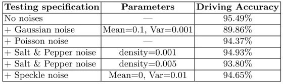
Group (1) Implementation: In this group, 709 out of 1064 (i.e., 2/3) frames
are randomly chosen for training and the remaining 355 (i.e., 1/3) frames are used for testing. We then repeat the experiment by adding various types of noises to the testing frames.
Testing specification Parameters Driving Accuracy
No noises — 95.49%
+ Gaussian noise Mean=0.1, Var=0.001 89.86%
+ Poisson noise — 94.37%
+ Salt & Pepper noise density=0.001 94.93%
+ Salt & Pepper noise density=0.005 93.80%
[image:8.612.166.446.100.184.2]+ Speckle noise Mean=0, Var=0.01 94.65%
Table 3: The driving accuracies of Group (1) Implementation
different types of noises, but is still reasonably acceptable. Gaussian noise has the worst effect, where the driving accuracy attained 89.86% (for Mean = 0.1 and Var = 0.001). This type of noise distributes the noise over to all the pixels of the input image, so it significantly affects the DRL-RT inputs. Nevertheless, the driving accuracy is still high. Other types of noises (Poisson, Salt & Pepper and Speckle) have reported high and comparable results. The driving accuracy achieved 94.37% after adding the Poisson noise, which was generated from the input data instead of adding artificial noise to the data [15]. By adding Salt & Pepper noise, the accuracies obtained 94.93% and 93.80% for the densities of 0.001 and 0.005, respectively. This type of noise influences some pixels, depending on the density. Therefore, the performance is still high after adding this noise. Finally, the speckle method multiplies a uniform noise with the original data and adds the noise back on [15]. We still attain a high accuracy (94.65%) in our models.
The above experiments confirm that our proposed approach can deal with different types of noises and produce acceptable outcomes.
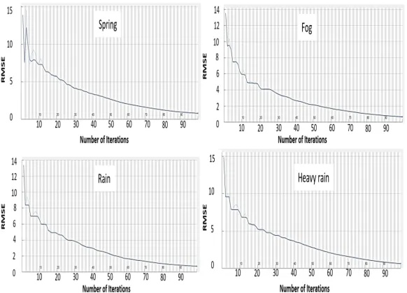
Group (2) Implementation: The training performance of the DRL-RT for
the four databases is given in Fig. 4. This figure demonstrates the relationships between the Root Mean Square Error (RMSE) and the training iterations during the NN training stages. The RMSE values are usually exploited to demonstrate the differences between desired values and output values. These differences are usually reduced along with the training iterations.
The first row of Table 4 shows that the driving accuracy attained its high-est value of 93.94% by using the spring environment database. This is because that the DRL-RT has analysed very clear provided images. The fog environment database obtained a high driving accuracy of 93.66%. Here, the overall views are blurred (or in a low quality) but all the input information can still be dis-tinguished, so the accuracy is only slightly reduced with respect to the spring views. The driving accuracy of the rain environment database achieved 89.55% and this is due to the noise effects of rain drops on image views. Finally, the inferior driving accuracy of 84.68% was recorded for the heavy-rain environment database as the amount of rain drops (or noise) is increased there.
Fig. 4: The training RMSE vs #iterations for the four environments
Testing specification Parameters Spring Fog Rain H-Rain
No noises — 93.94% 93.66% 89.55% 84.68%
+ Gaussian noise Mean=0.1, Var=0.001 79.55% 65.49% 59.70% 66.94%
+ Poisson noise — 88.64% 90.14% 91.04% 83.87%
+ Salt & Pepper noise density=0.001 90.91% 91.55% 89.55% 84.68%
+ Salt & Pepper noise density=0.005 90.91% 86.62% 82.84% 84.68%
+ Speckle noise Mean=0, Var=0.01 88.64% 90.14% 92.54% 83.87%
Table 4: The driving accuracies of Group (2) Implementation
a higher accuracy. If we compare different environments in Table 4, spring has a high or comparable value because there were already noises (fog or rain) in the other three environments.
3.2 Comparisons
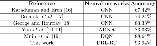
We have investigated and simulated various deep learning approaches to establish a fair comparison between our DRL-RT method and other work. Table 5 shows the accuracies of different deep learning networks by applying the SYNTHIA-SEQS-05-SPRING database. (Some parameters were adapted to allow accept-able comparisons.) The reason of selecting this database is that it has the clear environment, which is suitable to eliminate undesired effects and ensure a fair judgement.
[image:9.612.141.469.329.409.2]Reference Neural networks Accuracy
Karaduman and Eren [16] CNN 67.42%
Bojarskiet al.[17] CNN 74.24%
George and Routray [18] CNN 83.33%
Yunet al.[10, 11] ADNet 83.33% Mnihet al.[19] DQN 88.64%
[image:10.612.172.444.101.181.2]This work DRL-RT 93.94%
Table 5: A comparison between the DRL-RT method and other suggested networks
errors of obtaining precise outputs. The CNN used in [18] achieved 83.33%. This is also due to the architecture of this network, which was designed for classifying eye gaze directions. The ADNet used in [10, 11] attained the same accuracy of 83.33%. The essential problem lies in the rewards used there, which were basi-cally designed for recognising moved objects, as the rewards are updated in the stop action. In addition, the ADnet architecture is not entirely appropriate for road tracking tasks.
The work which is closest to ours is the influential Deep Q-Network (DQN) used in [19] and illustrated in [20], which achieved a reasonable accuracy of 88.64%. We believe that this is due to the introduction of DRL (i.e., the deep network and the Q-learning). Our proposed method has shown superior per-formance by attaining the accuracy of 93.94%. This may be due to the overall structure of our road tracking method including the network architecture, track-ing policy and designed codes.
4
Conclusion
In this paper, a deep reinforcement neural network DRL-RT has been proposed for road tracking. This network was trained and tested to guide driving cars un-der different weather environments. Different tracking instances were coded to represent the appropriate road tracking. The MDP concept is used here, where the network accepted states and produced actions by taking advantages from rewards. This study has been compared with other work and showed superior performance. In particular, we have achieved an accuracy of 93.94% in a clear environment, and accuracies 93.66%, 89.55% and 84.68% nder unclear environ-ments of fog, rain and heavy-rain respectively. These would set up a new baseline for further studies.
References
1. O. Grigore and O. Grigore, “Reinforcement learning neural network used in a
tracking system controller,” inProceedings 9th IEEE International Workshop on
Robot and Human Interactive Communication., pp. 69–73, 2000.
2. A. Cohen and V. Pavlovic, “Reinforcement learning for robust and efficient
real-world tracking,” in 20th International Conference on Pattern Recognition,
pp. 2989–2992, 2010.
3. F. Liu and J. Su, “Reinforcement learning-based feature learning for object
track-ing,” inProceedings of the 17th International Conference on Pattern Recognition.
4. J. Supanˇciˇc and D. Ramanan, “Tracking as online decision-making: Learning a
policy from streaming videos with reinforcement learning,” in2017 IEEE
Interna-tional Conference on Computer Vision (ICCV), pp. 322–331, 2017.
5. X. Jinlin, Z. Weigong, and G. Zongyang, “Neurofuzzy velocity tracking control
with reinforcement learning,” in9th International Conference on Electronic
Mea-surement Instruments, pp. 3–465–3–468, 2009.
6. A. Sootla, N. Strelkowa, D. Ernst, M. Barahona, and G. Stan, “On periodic ref-erence tracking using batch-mode reinforcement learning with application to gene
regulatory network control,” in52nd IEEE Conference on Decision and Control,
pp. 4086–4091, 2013.
7. J. Hall, C. E. Rasmussen, and J. Maciejowski, “Reinforcement learning with
ref-erence tracking control in continuous state spaces,” in 50th IEEE Conference on
Decision and Control and European Control Conference, pp. 6019–6024, 2011. 8. C. Wei, Z. Zhang, W. Qiao, and L. Qu, “Reinforcement-learning-based intelligent
maximum power point tracking control for wind energy conversion systems,”IEEE
Transactions on Industrial Electronics, vol. 62, no. 10, pp. 6360–6370, 2015. 9. E. Perot, M. Jaritz, M. Toromanoff, and R. d. Charette, “End-to-end driving in
a realistic racing game with deep reinforcement learning,” inIEEE Conference on
Computer Vision and Pattern Recognition Workshops, pp. 474–475, 2017. 10. S. Yun, J. Choi, Y. Yoo, K. Yun, and J. Y. Choi, “Action-decision networks for
vi-sual tracking with deep reinforcement learning,” inIEEE Conference on Computer
Vision and Pattern Recognition (CVPR), pp. 1349–1358, 2017.
11. S. Yun, J. Choi, Y. Yoo, K. Yun, and J. Y. Choi, “Action-driven visual object
track-ing with deep reinforcement learntrack-ing,”IEEE Transactions on Neural Networks and
Learning Systems, vol. 29, no. 6, pp. 2239–2252, 2018.
12. G. Ros, L. Sellart, J. Materzynska, D. Vazquez, and A. M. Lopez, “The synthia dataset: A large collection of synthetic images for semantic segmentation of
ur-ban scenes,” in IEEE Conference on Computer Vision and Pattern Recognition
(CVPR), pp. 3234–3243, 2016.
13. R. R. Omar, T. Han, S. A. M. Al-Sumaidaee, and T. Chen, “Deep finger texture
learning for verifying people,”IET Biometrics, vol. 8, pp. 40–48(8), 2019.
14. D. P. Kingma and J. Ba, “Adam: A method for stochastic optimization,”arXiv
preprint arXiv:1412.6980, 2014.
15. MATLAB,Image Processing Toolbox, For Use with MATLAB, Computation,
Vi-sualization, Programming. version 3. Natick, MA: The MathWorks Inc., 2001. 16. M. Karaduman and H. Eren, “Deep learning based traffic direction sign detection
and determining driving style,” inInternational Conference on Computer Science
and Engineering (UBMK), pp. 1046–1050, 2017.
17. M. Bojarski, D. Del Testa, D. Dworakowski, B. Firner, B. Flepp, P. Goyal, L. D.
Jackel, M. Monfort, U. Muller, J. Zhang,et al., “End to end learning for self-driving
cars,”arXiv preprint arXiv:1604.07316, 2016.
18. A. George and A. Routray, “Real-time eye gaze direction classification using
con-volutional neural network,” inInternational Conference on Signal Processing and
Communications (SPCOM), pp. 1–5, 2016.
19. V. Mnih, K. Kavukcuoglu, D. Silver, A. Rusu, J. Veness, M. Bellemare, A. Graves,
M. Riedmiller, A. K. Fidjeland, G. Ostrovski,et al., “Human-level control through
deep reinforcement learning,”Nature, vol. 518, no. 7540, p. 529, 2015.
20. K. Arulkumaran, M. P. Deisenroth, M. Brundage, and A. A. Bharath, “A brief