GSX-80™
Graphics Extension
Programmer's Guide
Digital Research P.O. Box 579
160 Central Pacific Grove, CA 93950
COPYRIGHT NOTICE
Copyright © 1982 by Graphic Software Systems, Incorporated and Digital Research. This item and the information contained herein are the confidential property of Graphic Software Systems, Incor-porated and Digital Research. No part may be reproduced, trans-mitted, transcribed, stored in a retrieval system, or translated into any human or computer language in any form or by any means, electronic, mechanical, magnetic, optical, chemical, manual, or otherwise, without the express written permission of Graphic Software Systems, Incorporated, 25117 SW Parkway, Wilsonville, Oregon, 97070, and Digital Research, Post Office Box 579, Pacific Grove, California, 93950.
The names GSS-KERNEL and GSS-PLOT are trademarks of Graphic Software Systems, Incorporated. The name GSX-80 is a trademark of Digital Research.
DISCLAIMER
Graphic Software Systems, Inc. and Digital Research make no representations or warranties with respect to the contents hereof and specifically disclaim any implied warranties or merchantabi-lity or fitness for any particular purpose. Further, Graphic Software Systems, Incorporated and Digital Research reserve the right to revise this publication and to make changes from time to time in the content hereof without obligation of Graphic Software Systems, Incorporated and Digital Research to notify any person or organization of such revision or changes.
First Edition: November 1982 Release Number: 1.0
[ill
DIGITAL
RESEARCH'Y
DATE: DECEMBER 1, 1982
TO: CP/MTM CARD OWNER
SUBJECT: GSX-80™ FUNCTION
Along with this CP/M Card package, you are recelvlng GSX-80 which is Digital Research's first graphics software product. GSX-80 is the graphic system extension to a-bit CP/M systems and provides graphic output functions through standard O/S calling procedures. We have included i t with the CP/M Card to give you the gateway to "CP/M GRAPHICSTMft which includes the following products as well ~s more to come from independent software vendors and DRI:
GSS-KERNELTM is a subroutine library of 2D graphic primitives for programmers and system builders. This product will provide a programmers interface to graphics that is consistent with the emerging ISO graphic standard GKS (Graphical Kernel System).
GSS-PLOTTM is a subroutine library of high level functions .for programmers who want bar graphs, pie charts, histograms, line graphs and sca~ter plots. This product makes it easy to write programs that produce typical business, ehgineering an~ scienti-fic data representation plots.
GSS-KERNEL and GSS-PLOT will link with PASCAL/MT+, PL/I-80, CB80 and FORTRAN source coded programs.
GSS-4S1S™ is a interactive utility that provides Tek-tronix 4010 terminal emulation for microcomputers that have graphic displays. This product is for the user who wants to access graphic software packages on time sharing systems. Any software package that produces Tektronix PLOT-10 compatible out-put can be accessed.
These products along with GSX-80 will bring portability to micro-computer graphic applications. Many output devices are also supported such as plotters, matrix printers and CRT terminals.
See your computer retailer for these graphic products and new ones that will be coming soon as part of dCP/M GRAPHICS."
CP/M CARDTM, GSX-SS™
t
PASCAL/MT+TM, PL/I-8S™,CB8S™, CP/M GRAPHICS M Digital Research, Inc.
GSS-KERNELTM, GSS-PLOTTM, GSS-4SlS™ Graphic Software Systems, Inc.
Preface
MANUAL OBJECTIVE
IRTENDBD AUDIENCE
MANUAL DESIGN
The purpose of this document is to describe the features and operation of the CP/M-80 Graphics System Extension, GSX-80. The manual will explain what GSX-80 does and how you can employ its graphics capabilities. It will also explain how GSX-80 interfaces to your, hardware environment and how you can adapt GSX-80 for your own unique graphics devices.
This manual is intended for systems programmers who are familiar with the CP/M Operating System and also have some knowledge of graphics programming.
This manual contains five sections, appen-dices, and an index. The following descrip-tions will help you determine a reading path through the manual.
Section 1 provides an overview of GSX-80. It explains the GSX-80 architecture and gives a preview of each component of GSX-80. Also, it describes how to use GSX-80 in conjunction with applications programs to provide graphics capability on your system.
Section 2 describes the Graphics Device Operating System (GDOS) in detail. It
includes the functions and calling conven-tions for GDOS as well as information about how device drivers are loaded during program execution.
All Information Presented Here is Proprietary to Graphic Software Systems, Incorporated and Digital Research
GSX-80 PROGRAMMER'S GUIDE PREFACE
CONVENTIONS USED IN THIS MANUAL
Section 3 treats the Graphics Input/Output (GIOS). It describes how to interface par-ticular graphics devices to GSX-80 to provide device independence for your application program.
Section 4 provides details abput the GSX Loader and its operation at the start of your program execution. It also describes how the GSX Loader is integrated with your applica-tion program using the GENGRAF utility. Section 5 describes the installation proce-dure for GSX-80 and also tells you how to debug application programs that use graphics. Appendixes containing the following informa-tion are provided for your convenience: Appendix A - Example graphics device driver
listings
Appendix B - The Virtual Device Interface specification
Appendix C - A glossary of GSX-80 unique terms
Appendix D - A summary of device character-istics for graphics device drivers included with the standard GSX-80 distribution Finally, an index will help you use this document more effectively.
Words appearing in bold type in the main text can be found in the Glossary, Appendix C.
All Information Presented Her~ is Proprietary to Graphic Software Systems, Incorporated and Digital Research
Table of Contents
SBC'l'IOR 1 OVERVIEW
INTRODUCTION •
GRAPHICS SYSTEM EXTENSION ARCHITECTURE
The Graphics Device Operating System (GDOS) The Graphics Input/Output System (GIOS) The GENGRAF Utility • • •
THE GRAPHICS KERNEL AND PLOT • APPLICATION PROGRAMS • • • •
SBC'l'IOR 2 GDOS
INTRODUCTION • GDOS FUNCTIONS
Trapping Graphics Calls • Dynamic Loading • • Transforming Points • • GDOS CALLING SEQUENCE
GDOS OPCODES •
LOADING DEVICE DRIVERS • Assignment Table Format • Memory Management • • • •
1
1
2 3
4
5
5
7
7
7
7
8
8
11 16 17 18
All Information Presented Here is Proprietary to Graphic Software Systems, Incorporated and Digital Research
GSX-80 PROGRAMMER'S GUIDE TABLE OP CONTENTS
SECTION 3 GIOS INTRODUCTION • THE PURPOSE OF GIOS DEVICE DRIVER FUNCTIONS CREATING A GIOS FILE • • •
SECTION 4 TIlE GEHGRAP UTILITY INTRODUCTION • •
THE GSX LOADER THE GENGRAF UTILITY
SECTION 5 OPERATIHG PROCEDURES INTRODUCTION • • • • • • • GSX-80 DISTRIBUTION FILES
RUNNING GRAPHICS APPLICATIONS UNDER GSX-80 • DEBUGGING GRAPHICS APPLICATIONS UNDER GSX-80 • DETERMINING USER PROGRAM AREA SIZE • •
CREATING A NEW DEVICE DRIVER • • • • •
19 19 20 23
25 25
29
31 31 32 33
34
35
All Information Presented Here is Proprietary to Graphic Software
Systems, Incorporated and Digital Research
[image:9.471.38.408.42.549.2]GSX-80 PROGRAMMER'S GOlDE TABLE OF CORTENTS
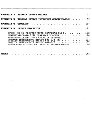
APPENDIX A EXAMPLE DEVICE DRIVER • • • • • • • • •
APPENDIX B VIRTUAL DEVICE INTERFACE SPECIFICATION
APPENDIX C GLOSSARY
APPENDIX D DEVICE SPECIFICS
EPSON MX-80 PRINTER WITH GRAFTRAX PLUS •• HEWLETT-PACKARD 7220 GRAPHICS PLOTTER
HEWLETT-PACKARD 7470A GRAPHICS PLOTTER • • HOUSTON INSTRUMENTS HIPLOT DMP-3/4-443 . . HOUSTON INSTRUMENTS HIPLOT DMP-6/7 • • • • • • VT100 WITH DIGITAL ENGINEERING RETROGRAPHICS •
37
59
117 121 122 124 127 134 137 139
INDEX • • • • • • • • • • • • • • • • • • • • • • • • • • • 143
All Information Presented Here is Proprietary to Graphic Software Systems, Incorporated and Digital Research
[image:10.471.79.436.94.543.2]GSX-80 PROGRAMMER'S GUIDE TABLE OP CORTENTS
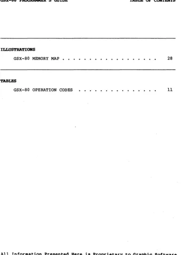
ILLUSTRATIONS
GSX-80 MEMORY MAP 28
TABLES
GSX-80 OPERATION CODES 11
All Information Presented Here is Proprietary to Graphic Software Systems, Incorporated and Digital Research
[image:11.469.38.406.50.555.2]Section 1
OVERVIEW
IR'l'RODUC'l'IOR
GRAPHICS SYSTEM EXTERSIOR
ARCHITECTURE
This section gives you an overview of the Graphics System Extension architecture, its components and their functions. Later sec-tions describe each of these parts in detail.
GSX-80 is the Graphics System Extension for the CP/M family of operating systems. It incorporates graphics capability into the operating system and provides a host and device independent interface for your appli-cations programs. Graphics primitives are provided for implementing graphics applica-tions with reduced programming effort. In addition, GSX-80 offers program portability by allowing an application to run on any CP/M system with the GSX-80 option. GSX-80 also promotes programmer portability by providing a common programmer interface to graphics which is compatible with one of the world's most widely used operating systems, CP/M. GSX-80 is implemented as an integral part of your operating system. Application programs interface to GSX-80 through a standard cal-ling sequence similar to the BDOS conven-tions. Drivers for specific graphics devices translate the standard GSX-80 calls to the unique characteristics of the device. In this way, GSX-80 provides device-independence since the peculiarities of the graphics de-vice'are not visible to the application program.
All Information Presented Here is Proprietary to Graphic Software Systems, Incorporated and Digital Research
GSX-80 PROGRAMMER'S GUcrDE OVERVIEW
THE GRAPHICS DEVICE OPERATING SYSTEM
GSX-80 consists of several parts that work together to give your system graphics capability:
• the Graphics Device Operating System (GDOS) ,
• the Graphics Input/Output System (GIOS) and,
• the GERGRAP utility
The Graphics Device Operating System (GDOS) contains the basic host and device indepen-dent graphics functions that can be called by your application program. GOOS provides a standard interface to graphics which is con-stant regardless of specific devices or host hardware, just as the BOOS standardizes disk interfaces. Your application program acces-ses GOOS through a mechanism analogous to the normal BOOS system calls.
GDOS loads at run time with your graphics application program, so i t consumes system memory space only when required, leaving the normal Transient Program Area for non-graphic programs.
GOOS performs coordinate scaling so that your program can specify points in a normalized coordinate space. It uses device specific information to translate the normalized coor-dinates into the corresponding values for your particular graphics device.
All Information Presented Here is Proprietary to Graphic £oftware Systems, Incorporated and Digital Research
GSX-80 PROGRAMMER'S GUIDE OVERVIEW
THE GRAPHICS INPUT/OUTPUT SYSTEM
Multiple graphics devices can be supported under GSX-80 within a single application. By referr ing to devices with a workstation iden-tification number, graphics information can be sent to anyone of several resident devices. GDOS dynamically loads a specific device driyer when requested by the applica-tion program, overlaying the previous driver. This technique minimizes memory size require-ments since only one driver is resident at any time. For details see "Loading Device Drivers" in Section 2.
The Graphics Input/Output System (GIOS) is similar to the Basic I/O system or BIOS. It provides the device specific code required to interface your particular graphics devices to the GDOS. GIOS consists of a set of Device Drivers that communicate directly with the graphics devices through the appropriate host ports. A unique device driver is required for each different graphics device on your system. The term GIOS refers to the collec-tion of available device drivers as well as the particular driver that is loaded into memory when required by your application. Although a single program can use several graphics devices, only one driver is loaded by GDOS at a time.
GIOS performs the graphics priaitives of GSX-80, consistent with the inherent capabilities of your graphics device. In some cases a device driver will emulate standard GDOS capabilities which are not provided by the graphics device hardware. For example, some devices may require that dashed lines be simulated by a series of short vectors gen-erated in the device driver.
All Information Presented Here is Proprietary to Graphic Software Systems, Incorporated and Digital Research
GSX-80 PROGRAMMER'S GUIDE OVERVIEW
THE GENGRAF UTILITY
GSX-80 is supplied with drivers for many of the most popular graphics devices for micro-compu ter systems. However, you may ins tall your own custom device driver if necessary. We provide information in Section 3, "GIOS," to help you write your driver, including the Virtual Device Interface (VOl) Specification which defines all the required functions and parameter conventions. In addition, we include a sample device driver in Appendix B.
The GENGRAF utility is used to combine your application program and the GSX Loader into one executable .COM file. The GSX Loader is a small program that loads the GDOS and GIOS into memory at run-time and establishes the links between your application program and GDOS. The GSX Loader is attached to your application program after i t has been compiled/assembled and linked with the re-quired external routines and libraries.
All Information Presented Here is Proprietary to Graphic Software Systems, Incorporated and Digital Research
GSx-80 PROGRAMMER'S GUIDE OVERVIEW
THE GRAPHICS
KERREL AND PLOT
APPLICATION PROGRAMS
GSX-80 defines a standard interface to graphics from your application program using a BDOS-like access method. GSX-80 also sup-ports higher level graphics interfaces. GSS-KERNEL is a graphics application library which is based on the Graphical Kerne1 System (GKS), level OA, a draft international graphics standard which gives you extremely powerful graphics capabilities. GSS-KERNEL supports the popular high level languages such as Pascal, Fortran and PL/I with stan-dard graphics procedure calls. GSS-PLOT is a high level programming tool that allows you to produce graphs and plots with just a few calls from a high level language.
GSS-KERNEL and GSS-PLOT are available for CP/M from Digital Research as separate pro-gram products. GSX-80 is the basis for these products since i t provides host and device independent access to graphics primitives.
You can wr i te your applications programs in assembly language (or a high level language that supports the GSX-80 calling conventions) with appropriate calls to GDOS. Programs are compiled/assembled and linked in the normal manner with the addition of one extra step. Before executing your application program you must attach the GSX Loader using the GENGRAF utility supplied with GSX-80. This results in an executable .COM file. See Section 4, "The GENGRAF Utility," for details.
End of Section I
All Information Presented Here is Proprietary to Gyaphic Software Systems, Incorporated and Digital Research
GSX-80 PROGRAMMER'S GUIDE OVERVIEW
All Information Presented Here is Proprietary to Graphic Softw~re Systems, Incorporated and Digital Research
Section 2
GOOS
IN'l'RODUC'rIOR
GDOS FORC"HORS
TRAPPING GRAPHICS CALLS
DYNAMIC LOADING
In this section we describe the Graphics Device Operating System (GDOS) in detail, including GDOS functions, the GDOS calling sequence, and how Device Drivers are loaded.
GDOS performs several functions during the execution of a graphics application program, including:
• trapping all system function calls, • loading device drivers as required,
• converting normalized coordinates to device coordinates.
GDOS interfaces to the normal BOOS calling sequence by trapping all calls to BOOS and examining the function code in register C. If the code is lIS, the call is a graphics request and is serviced by GDOS. Otherwise, the request is passed on to BOOS to be serviced in the normal manner. See the nGSX Loader n in Section 4 for details.
Each time a workstation is opened, GDOS determines whether the required device driver is resident in memory. If not, GDOS loads the driver from disk and then services the graphics request.
All Information Presented Here is Proprietary to Graphic Software Systems, Incorporated and Digital Research
GSX-80 PROGRAMMER'S GUIDE GDOS
TRANSFORMING POINTS
GDOS CALLING SEQUENCE
All graphics coordinates are passed to GOOS as Normalized Device Coordinates (NDC) in a range from 0 to 32767 in both axes. Using information passed from the device driver when the workstation (device) was opened, GOOS scales the NOC coordinates to the device coordinates. The full scale NOC space is always mapped to the full dimensions of your graphics device in each axis. In this way you are assured that all your graphics infor-mation will appear on the display surface regardless of the dimensions of your device.
GSX-80 provides the programmer with a standard way to access graphics capabilities. This accessing method is referred to as the GSX-80 Virtual Device Interface (VDI) since i t makes all graphics devices appear "virtu-ally" identical. The implementation of the VOl employs the conventional BOOS calling sequence with a function code of 115. That is, the decimal number 115 (73 Hexidecimal) is loaded into register C, and a subroutine call is made to location 5. Arguments to GOOS are passed in a parameter l i s t pointed to by the contents of the double register DE. The parameter l i s t is in the form of five arrays: a control array, an array of input parameters, an array of input point coordi-nates, an array of output parameters, and an array of output point coordinates. The spe-cific graphics function to be performed by GDOS is indicated by an operation code in the parameter list.
All Information Presented Here is Proprietary to Graphic Software Systems, Incorporated and Digital Research
GSX-80 PROGRAMMER'S GOlDE GDOS
The GOOS calling sequence is summar ized below:
GOOS CALLING SEQUENCE:
Function code (in register C)
=
115 Parameter block address in register OE Parameter block contents:PB PB+2 PB+4 PB+6 PB+8
Address of control array
Address of input parameter array Address of input point coordinate array
Address of output parameter array Address of output point coordinate array
Control Array on Input: contrl(l)
contrl(2) contrl (4)
-opcode for driver function -number of vertices in input
point array
-length of input parameter array
contrl(6-n) -opcode dependent
Input Parameter Array:
intin -array of input parameters
Input Coordinate Array:
ptsin -array of input coordinates (each point is specified by an X and Y coordinate given in Norma-lized Device Coordinates between
o
and 32,767.)All Information Presented Here is Proprietary to Graphic Software Systems, Incorporated and Digital Research
GSX-80 PROGRAMMER'S GUIDE GDOS
Control Array on Output:
contrl(3) -length of output coordinate array contrl(S) . -number of vertices in output
point array contrl(6-n) -opcode dependent
Output Parameter Array:
intout -array of output parameters
Output Point Coordinate Array:
ptsout -array of output coordinates (each point is specified by an X and Y coordinate given in Norma-lized Device Coordinates between
o
and 32,767.)NOTE: All array elements are type INTEGER (2 bytes). The meaning of the input and output parameter arrays is dependent on the opcode. See the "Virtual Device Interface Specifica-tion," Appendix B, for details.
All Information Presented Here is Proprietary to Graphic Software Systems, Incorporated and Digital Research
GSX-80 PROGRAMMER'S GOlDE GDOS
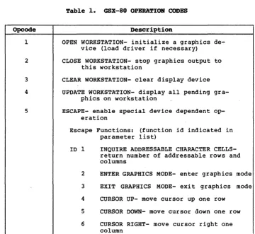
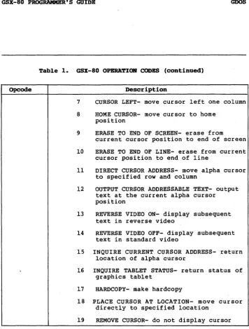
GDOS OPCODBS Table 1 summarizes the GDOS opcodes. See Section 3 for a detailed description of all the operation codes including parameters.
~able 1. GSX-80 OPERA~IOR CODES
Opcode Description
1
2
3 4
5
OPEN WORKSTATION- initialize a graphics de-vice (load driver if necessary)
CLOSE WORKSTATION- stop graphics output to this workstation
CLEAR WORKSTATION- clear display device UPDATE WORKSTATION- display all pending
gra-phics on workstation
ESCAPE- enable special device dependent op-eration
Escape Functions: (function id indicated in parameter list)
ID 1 INQUIRE ADDRESSABLE CHARACTER CELLS-return number of addressable rows and columns
2 ENTER GRAPHICS MODE- enter graphics mode 3 EXIT GRAPHICS MODE- exit graphics mode 4 CURSOR UP- move cursor up one row
5 CURSOR DOWN- move cursor down one row 6 CURSOR RIGHT- move cursor right one
column
All Information Presented Here is Proprietary to Graphic Software Systems, Incorporated and Digital Research
[image:22.469.76.436.202.533.2]GSX-80 PROGRAMMER'S GUIDE GDOS
Table 1. GSX-80 OPERATION CODES (continued)
Opcode Description
7 CURSOR LEFT- move cursor left one column 8 HOME CURSOR- move cursor to home
position
9 ERASE TO END OF SCREEN- erase from
current cursor position to end of screen 10 ERASE TO END OF LINE- erase from current
cursor position to end of line
11 DIRECT CURSOR ADDRESS- move alpha cursor to specified row and column
12 OUTPUT CURSOR ADDRESSABLE TEXT- output text at the current alpha cursor position
13 REVERSE VIDEO ON- display subsequent text in reverse video
14 REVERSE VIDEO OFF- display subsequent text in standard video
15 INQUIRE CURRENT CURSOR ADDRESS- return location of alpha cursor
16 INQUIRE TABLET STATUS- return status of graphics tablet
17 HARDCOPY- make hardcopy
18 PLACE CURSOR AT LOCATION- move cursor directly to specified location
19 REMOVE CURSOR- do not display cursor
All Information Presented Here is Proprietary to Graphic Software Systems, Incorporated and Digital Research
[image:23.471.39.396.50.520.2]GSX-80 PROGRAMMER'S GUIDE
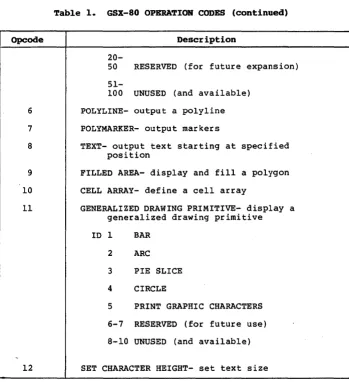
Table 1. GSX-80 OPERATION CODES (continued)
Opcode Description
6
7
8
9 10 11
12
20-50 RESERVED (for future expansion)
51-100 UNUSED (and available) POLYLINE- output a polyline POLYMARKER- output markers
TEXT- output text starting at specified position
FILLED AREA- display and fill a polygon CELL ARRAY- define a cell array
GENERALIZED DRAWING PRIMITIVE- display a generalized drawing primitive ID 1 BAR
2 ARC 3 PIE SLICE 4 CIRCLE
5 PRINT GRAPHIC CHARACTERS 6-7 RESERVED (for future use) 8-10 UNUSED (and available)
SET CHARACTER HEIGHT- set text size
GDOS
All Information Presented Here is Proprietary to Graphic Software Systems, Incorporated and Digital Research
[image:24.470.81.431.139.521.2]GSX-80 PROGRAMMER'S GUIDE
Table 1. GSX-80 OPERA'.lIOB CODES (continoed)
Opcode Description
13 14
15
16 17
18
19
20
21
22
23
24
25
26
SET CHARACTER UP VECTOR- set text direction SET COLOR REPRESENTATION- define the color
associated with a color index SET POLYLINE LINETYPE- set linestyle for
polylines
SET POLYLINE LINE WIDTH- set width of lines SET POLYLINE COLOR INDEX- set color for
polylines
SET POLYMARKER TYPE- set marker type for polymarkers
SET POLYMARKER SCALE- set size for polymarkers
SET POLYMARKER COLOR INDEX- set color for polymarkers
SET TEXT FONT- set device dependent text style
SET TEXT COLOR INDEX- set color of text SET FILL INTERIOR STYLE- set interior style
for polygon fill
SET FILL STYLE INDEX- set fill style for polygons
SET FILL COLOR INDEX- set color for polygon fill
INQUIRE COLOR REPRESENTATION- return color representation values of index
GDOS
All Information Presented Here is Proprietary to Graphic Software Systems, Incorporated and Digital Research
[image:25.476.36.392.78.547.2]GSX-80 PROGRAMMER'S GUIDE
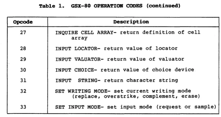
Table 1. GSX-80 OPERATION CODES (continued)
Opcode Description
27
28 29
30
31 32
INQUIRE CELL ARRAY- return definition of cell array
INPUT LOCATOR- return value of locator INPUT VALUATOR- return value of valuator INPUT CHOICE- return value of choice device INPUT STRING- return character string SET WRITING MODE- set current writing mode
(replace, overstrike, complement, erase)
GDOS
33 SET INPUT MODE- set input mode (request or sample)
All Information Presented Here is Proprietary to Graphic Software Systems, Incorporated and Digital Research
[image:26.469.71.437.146.341.2]GSX-80 PROGRAMMER'S GUIDE GDOS
LOADING DEVICE DRIVERS
The GSX-80 Virtual Interface refers to graphics devices as workstations. Each time a graphics device is to be used, i t must first be initialized with an OPEN WORKSTATION operation. This will cause the device to be initialized with selected attributes such as I ine type, color, etc., and i t will also return information about the device to GDOS~
When the OPEN WORKSTATION operation is per-formed, GDOS determines whether the correct device driver is currently in memory. It does this by comparing the workstation ID which is specified in the OPEN WORKSTATION call with the workstation IO of the device whose driver is currently loaded. If there is a match (the correct driver is in memory), the graphics request is serviced immediately. If there is not a match, then GOOS must load the correct device driver. In order to do this, GOOS refers to a data structure called the Assignment Table which contains informa-tion about the available device drivers and the files where they are stored.
GOOS searches the Assignment Table for a device driver entry with a driver number which matches the workstation IO requested in the OPEN WORKSTATION call. If i t finds the correct driver entry, GDOS will load the new device driver above itself where the previous driver was located. When the load is com-plete, GDOS will finish the OPEN WORKSTATION operation and then return to the calling program.
If there is no match in the Assignment Table when a new driver is required, GDOS will return without loading a driver. Therefore the previous graphics device will continue to be the open workstation.
All Information Presented Here is Proprietary to Graphic Software Systems, Incorporated and Digital Research
GSX-80 PROGRAMMER'S GUIDE GDOS
ASSIGNMENT TABLE
FORMAT The Assignment Table consists entirely of text and may be created or modified with any text editor. It must reside in a file named ASSIGN.SYS on the currently logged drive when GSX-80 is operating. For each device driver, there is an entry containing the driver number, which signifies the workstation ID of the associated device, and the name of the file containing the associated graphics de-vice driver. The name of the dede-vice driver file may be any legal CP/M unambiguous file-name. Any device to be used during a graphics session must have an entry in the Assignment Table corresponding to the name of its associated driver.
The format for entries in the Assignment Table is:
DDXd:fi1ename
DD
=
Logical driver number X=
spaced
=
Disk drive codefilename
=
the driver filename (valid unambi-guous CP/M filename of up to eight upper case characters, .PRL extension required)For example, a valid entries in the Table would be: 11 A:DDPLOT
1 B:CRTDRV 21 A:PRINTR
All Information Presented Here is Proprietary to Graphic Software Systems, Incorporated and Digital Research
GSX-80 PROGRAMMER'S GUIDE GDOS
MEMORY MANAGEMENT
There is a convention for assigning device driver numbers (workstation ID's) to graphics devices. This is done to assure the maximum degree· of device independence within applica-tions programs. The convention for driver numbers is:
o
1-10 11-20 21-30 32-40
Default console CRT
Plotter Printer Other devices
When execution of your graphics program be-gins, the GSX Loader allocates memory for the first device driver in the Assignment Taple at the top of the Transient Program Area, just below BDOSs This driver is referred to as the Default Device Driver. Subsequently, GDOS causes all new dr i ver s to be loaded into the same area where memory was allotted for the original device driver. To prevent ne~
drivers fro~ writing ~ and destroying ~
portion of BOOS, ~hich follo~~ the device driver, make sure that the first driver in the AssigrimEmt Table is the largest driver to be loaded .§.Q that ample memory space is allo-cated Qy the GSX Loader for all subsequent drivers. An error is reported if an attempt is made to load a driver larger than the default driver.
End of Section 2
All Information Presented Here is Proprietary to Graphic Software Systems, Incorporated and Digital Research
Section 3
GIOS
INTRODUCTION
TIlE PURPOSE OF GIOS
In this section we describe the Graphics Input/Outpu t System, or GIOS. The informa-tion in this secinforma-tion will allow you to write. and install your own custom drivers for unique graphics devices.
NOTE: If your disk does not include all the GIOS modules documented in this manual, contact your OEM or distributor.
As we discussed earlier, GSX-80 is composed of three components: the Graphics Device Operating System (GDOS), the Graphics Input/Output System (GIOS), and the GSX Loader. GOOS contains the device independent graphics functions, while GIOS contains the device dependent code. This division is consistent with the CP/M philosophy of iso-lating device dependencies so that the prin-cipal parts of the operating system are transportable to many systems and so that applications can run independent of the spe-cific devices connected to the system. In this context, GIOS is analogous to the BIOS but pertains to graphics devices only. GIOS contains a device driver for each of the graphics devices on the system.
A difference between GIOS and BIOS is that whereas all device drivers contained within BIOS are resident in memory simultaneously, only one graphics device driver is resident at any time. That is, only one graphics device is active at a time, although the active device may be changed by a request from the application program. GOOS insures
All Information Presented Here is Proprietary to Graphic Software Systems, Incorporated and Digital Research
GSX-80 PROGRAMMER'S GUIDE GIOS
DEVICE DRIVER PURCTIOHS
VIRTUAL DEVICE INTERFACE SPECIFICATION
that the correct driver is in memory when required. Because GIOS drivers are loaded dynamically, they must be stored on disk in relocatable format, as .PRL file types.
Device Drivers use the intrinsic graphics capabilities of devices to implement graphics primitives for GDOS. In some cases the graphics device itself does not support all the GDOS operations directly and the driver must emulate the capability in software. As an example, if a plotter cannot produce a dashed line, the driver must emulate it by converting a single dashed line into a series of short vectors and transmitting them to the plotter, giving the same end result.
Device drivers must conform to the GSX-80 Virtual Device Interface (VOl) Specification. The VDI specifies the calling sequence to access device driver functions as well as the syntax and semantics of the data structures that communicate across the interface.
Arguments to device drivers are passed in a parameter list pointed to by the contents of the double register DE. The parameter list is in the form of five arrays: a control array, an array of input parameters, an array of input point coordinates, an array of out-put parameters, and an array of outout-put point coordinates. The specific graphics function to be performed by a device driver is indi-cated by an operation code in the parameter list.
All Information Presented Here is Proprietary to Graphic Software Systems, Incorporated and Digital Research
GSX-80 PROGRAMMER' S GUIDE GIOS
The device driver calling sequence is summa-rized below:
DEVICE DRIVER CALLING SEQUENCE:
Parameter block address in register DE
Parameter block contents:
PB PB+2 PB+4 PB+6 PB+8
Address of control array
Address of input parameter array Address of input point coordinate
array
Address of output parameter array Address of output point coordinate
array
Control Array on Input: contrl (1)
contrl (2)
contrl (4) contrl(6-n)
-opcode for driver function -number of vertices in input
point array
-length of input parameter array
-opcode dependent
Input Parameter Array:
intin -array of input parameters
Input Coordinate Array:
ptsin -array of input coordinates
(each point is specified by an X and Y coordinate given in Device Coordinates)
All Information Presented Here is Proprietary to Graphic Software Systems, Incorporated and Digital Research
GSX-80 PROGRAMMER'S GUIDE GIOS
Control Array on Output: contrl{3)
contrl{S)
-length of output coordinate array -number of vertices in output
point array contrl{6-n) -opcode dependent
Output Parameter Array:
intout -array of output parameters
Output Point Coordin~te Array:
ptsout -array of output coordinates (each point is specified by an X and Y coordinate given in Device Coordinates)
All array elements are type INTEGER (2 bytes). The meaning of the input and output parameter arrays is dependent on the opcode. See the Virtual Device Interface Specifica-tion, Appendix B, for details.
All graphics coordinates are passed to the device driver as Device Coordinates. Using information passed from the device driver when the workstation (device) was opened, GDOS scales the NDC coordinates, passed from the application, to the coordinates of the specific device.
The full scale NDC space is always mapped to the full dimensions of your graphics device in each axis. In this way you are assured that all of your graphics information is visible on the display surface regardless of the actual device dimensions.
All Information Presented Here is Proprietary to Graphic Software Systems, Incorporated and Digital Research
GSX-80 PROGRAMMER'S GUIDE GIOS
CREA~ING A GlOS
If your device has an aspect ratio that is not 1:1 (Le., the dis'play surface is not square), and you wish to prevent distortion between your world coordinate system and the device coordinate system, then in your appli-cation you must use different scaling factors in the X and Y axes to compensate for the asymmetry of your device. For example, if you are using a typical CRT device with an aspect ratio of 3:4 (vertical: horizontal), to produce a perfect square on the display, you would draw a figure with 4000 NDC units vertically and 3000 NDC units horizontally. That is, the scaling factor for the vertical dimension is 4/3 of the horizontal direction. For most non-cr i tical applications you need not make this adjustment.
Details of the Virtual Device Interface including required and optional functions and arguments are included in Appendix B, "Vir-tual Device Interface Specification."
Device driver files that are part of GIOS must be in relocatable format so they can be loaded by the GSX Loader and GDOS. You may write a device driver in any language as long as the functions and parameter passing con-ventions conform to the Virtual Device Inter-face Specification given above. After assem-bling or compiling your driver source, link it with any required external subroutines and run-time support libraries using LINK-SO to produce a relocatable load module.
All Information Presented Here is Proprietary to Graphic Software Systems, Incorporated and Digital Research
GSX-80 PROGRAMMER' S GUIDE GIOS
When naming the device driver file the name used must contain six characters and must have a .PRL extension. In addition, if the driver is to be used by a graphics application, i t must be included in the Assignment Table. This is a text file named' ASSIGN.SYS on the currently logged disk. Each device entry in the Assignment Table has the form:
DDXd:filename where DD
X d filename
device driver number (worksta-tion ID)
=
a space=
the disk drive codethe driver filename (valid unambiguous CP/M filename--up to eight upper case characters required)
See "Assignment Table Format" in Section 2 on GDOS for more details.
End of Section 3
All Information Presented Here is Proprietary to Graphic Software Systems, Incorporated and Digital Research
Section 4
THE GENGRAF UTILITY
IN'l'RODUC'HOR
THE GSX LOADER
GSX LOADER RUN-TIME PROCEDURES
In this section we describe the GSX-80 utility GENGRAF and the GSX Loader. The GSX Loader brings GDOS into memory in preparation for execution of your graphics application program. GENGRAF is used to attach the GSX Loader to your program creating an executable .COM file.
GDOS is not resident in memory when the op-erating system is initialized, but is loaded when you execute your graphics application program. In this way, maximum space is pre-served for non-graphics programs.
Loading of GDOS at run-time is performed by a special program called the GSX Loader. The GSX Loader also br ings the Assignment Table into memory from a file named ASSIGN.SYS on the currently logged disk and then allocates memory space for the first (default) device driver named in the Assignment Table. Finally, the GSX Loader establishes the linkage between GDOS and the normal BDOS entry point at location 5 by moving some pointers.
The GSX Loader comes into memory with your graphics application program and r~ceives
control before execution of your program begins. The procedure for attaching the GSX Loader to your program is explained below.
After the GSX Loader is brought into memory with your program (through the normal opera-tion of the Console Command Processor) i t immediately receives control and performs the following operations.
All Information Presented Here is Proprietary to Graphic Software Systems, Incorporated and Digital Research
GSX-80 PROGRAMMER'S GUIDE
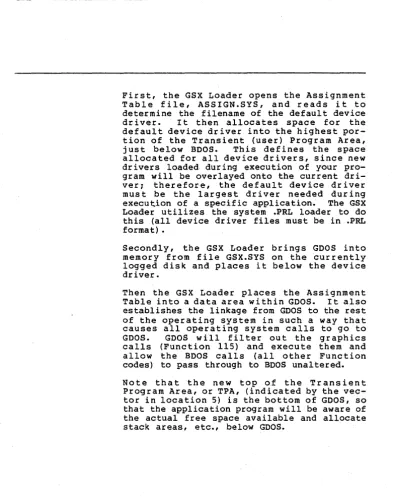
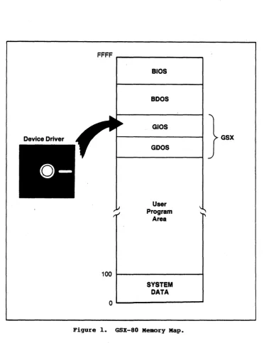
First, the GSX Loader opens the Assignment Table file; ASSIGN.SYS, and reads i t to determine the filename of the default device dr i ver. I t then alloca tes space for the default device driver into the highest por-tion of the Transient (user) Program Area, just below BOOS. This defines the space allocated for all device drivers, since new drivers loaded during execution of your pro-gram will be overlayed onto the current dri-ver; therefore, the default device driver must be the largest driver needed during execution of a specific application. The GSX Loader utilizes the system .PRL loader to do this (all device driver files must be in .PRL format) •
Secondly, the GSX Loader brings GOOS into memory from file GSX.SYS on the currently logged disk and places it below the device driver.
Then the GSX Loader places the Assignment Table into a data area wi thin GOOS. It also establishes the linkage from GOOS to the rest of the operating system in such a way that causes all operating system calls to go to GOOS. GOOS will filter out the graphics calls (Function 115) and execute them and allow the BOOS calls (all other Function codes) to pass through to BOOS unaltered. Note that the new top of the Transient Program Area, or TPA, (indicated by the vec-tor in location 5) is the bottom of GOOS, so that the application program will be aware of the actual free space available and allocate stack areas, etc., below GOOS.
All Information Presented Here is Proprietary to Graphic Software Systems, Incorporated and Oigital Research
[image:37.471.30.423.45.541.2]GSX-80 PROGRAMMER'S GUIDE GERGBAP
Finally, the GSX Loader moves the application program down from its position above the GSX Loader to the start of TPA, location IOOH. The space that was taken up by the Load"er can be utilized during the execution of the application program. Control is then transferred to location IOOH, the start of the application program. See Figure 1.
All Information Presented Here is Proprietary to Graphic Software Systems, Incorporated and Digital Research
GSX-80 PROGRAMMER'S GUXDE
FFFF ...-_ _ _ _ _ _ _ ---,
100
alos
aDos
GIOS
GOOS
User Program
Area
SYSTEM
DATA
0 1 . . - - - '
Figure 1. GSX-80 Memory Map.
GERGRAP
GSX
All Information Presented Here is Proprietary to Graphic Software Systems, Incorporated and Digital Research
[image:39.473.42.415.56.540.2]~
GSX-80 PROGRAMMER'S GUIDE GERGRAF
TIlE GERGRAP' UTILITY
Your application program may be written in any language provided the GDOS protocol is observed. You may compile/assemble and link your application in the normal manner, yielding a .COM executable file. One addi-tional step must be performed, however, before executing your graphics program: the GSX Loader must be attached to the front of your program so that i t can prepare the operating system environment for your graphics application.
The GENGRAF utility (provided with the GSX-80 distribution) allows you to attach the loader to your program "with one simple command: GENGRAF <filename>
For example, if your graphics application program were in an executable file named MYFILE.COM, then the following command string would attach the GSX Loader and place the result into file MYFILE.COM.
GENGRAF MYFILE
The resulting MYFILE.COM file would be ready to run.
You should be aware of the total memory space available to your application program in the TPA. This will be less for graphics applica-tions than for normal programs because of the GDOS and device driver requirements. We will explain "how to calculate the exact size of the TPA in Section 5, "Operating Procedures."
End of Section 4
All Information Presented Here is Proprietary to Graphic Software Systems, Incorporated and Digital Research
GSX-80 P~'S GUIDE
All Information Presented Here is Proprietary to Graphic Software Systems, Incorporated and Digital Research
Section 5
OPERATING PROCEDURES
IRTRODUCTl:ON
GSX-80 DIS'rRDJO'fiOR FILES
This section explains how to employ GSX-80 in your graphics applications. It also gives you some aids for debugging your application programs and determining the user program area available on your system. Finally, i t describes how to create and install a new graphics device driver under GSX-80.
When you receive your GSX-80 distribution diskette, first check to insure that all required files have been included. The following files should be present on your diskette:
ASSIGN.SYS this is the default assignment table file which associates specific device drivers with logical device numbers.
GSX.SYS this is the GSX-80 executable file. GENGRAF.COM this is the GENGRAF utility file which is used to attach the GSX Loader to your application program.
DDxxxx.PRL there will be one file with this naming convention for each device driver. The xxxx will be unique for each device and will usually be derived from the device tradename or model number •
.!!
any ~ ~ missing, contact your dis-tributor to receive a new diskette. If all files arePresent, make ibackup of the dis-tribution diskette using the PIP utility and store your distribution diskette in ~ safe place. Then, using the backup diskette, transfer the GSX-80 files to your working ~y~~~!!! £i~~~~~~ ~l~~Y~ ~~~ !h~ £~£~~£ diskette to generate any ne~ copies of GSX-80. Do not use the distribution diskette forrou
t inec;pe
rations.-All Information Presented Here is Proprietary to Graphic Software Systems, Incorporated and Digital Research
[image:42.471.37.430.67.539.2]GSX-80 PROGRAMMER'S GUIDE OPERA~G PROCEDURES
RUNRDlG GRAPHICS APPLICATIONS URDER GSX-80
In order to use the graphics features Provided by GSX-80, you must insure that several conditions are met:
1. In your application program you must conform to the GSX-80 calling convention to access graphics primitives. This involves making a call to the operating system in the normal manner with a function code of 115 (115 in register C, CALL to location 5). In addition, an address must be placed in regis-ter DE when the call is made which points to a parameter list that provides information to GSX-80 and also returns information to the calling program. The details of this proce-dure are contained in the sections on GDOS and GIOS and in Appendix B, "The Virtual Device Interface Specification."
2. After successfully compiling/assembling and linking your application program, you must perform one additional step before running your program. Using the GENGRAF utility provided with GSX-80, you must append the GSX Loader to your program. This is done with a simple command string. If your program was named MYFILE.COM on the currently logged disk, then the command would appear as follows:
A>GENGRAF MYFILE
The .COM extension is assumed by GENGRAF.
All Information Presented Here is Proprietary to Graphic Software Systems, Incorporated and Digital Research
GSX-80 PROGRAMMER' S GUIDE OPERATDfG PROCBD1JBES
DEBUGGING GRAPJ[[CS
APPLYCAfiORS ORDER GSX-80
3. You must insure that the required device drivers are present on the currently logged disk when your program is executed. Also, the Assignment Table must contain the names of your device drivers and a logical device number or workstation ID which corresponds to the correct device driver. The details of device driver and Assignment Table requirements are included in Section 2, "GDOS," and Section 3, "GIOS."
The GSX Loader, attached to your application using GENGRAF, loads GSX-80 from the disk along with the default device driver. It then moves the actual application code down to the normal TPA start address at location 100H (r e fer to Sec tion 4, "The GENGRAF Utility"). To debug a program using SID or DDT, type the following:
SID MYPROG.COM MYPROG.SYM or
DDT MYPROG.COM
The debugger will respond with a prompt: * First, you must determine where GSX-80 is lo-cated. This will also tell where the top of the TPA area is. Type the following to start the GSX Loader and break before the appli-cation program is moved down to loappli-cation 100H:
*G,103
To find out where GSX-80 is located you must look at the GDOS jump vector at locations 5
through 7 (JMP <address». Type: *D5,7
All Information Presented Here is Proprietary to Graphic Software Systems, Incorporated and Digital Research
GSx-80 PROGRAMMER'S GU:rnE OPERATIRG PBOCBDURES
DETEBMIRIBG USER
PROGRAM AREA SIZE
The debugger will display the contents of locations 5 through 7:
C3 00 9B
This indicates that GSX-80 is at location 9BOO (C3 is the JMP opcode). The last instruction location before the end of the TPA is the GSX-80 location minus 3, in this case 9BOO-3
=
9AFD.NOTE: Your TPA may be in a different place. Always subtract 3 from the contents of address 6,7 to determine the top of the TPA. Now, to view your program before i t begins execution, set a breakpoint that will occur when the last location of the TPA (determined above) is moved down by the GSX Loader: *G,9AFD
Then you may list your program which is now located at 100R:
*LIOO
To determine the amount of memory required to run a given application, make the following calculation:
Size of TPA in bytes
=
(Size of GSX.SY~ +[8 * (Size of PRL file of largest device driver used during the application)]
I
9 +(Size of application COM file after running GENGRAF) + 20
All Information Presented Here is Proprietary to Graphic Software Systems, Incorporated and Digital Research
GSX-80 PROGRAMMER'S GUIDE OPERA'.rIRG PROCEDURES
CREATIRG A NEW
DEVICE DRIVER
GSX-80 is distributed with a number of device drivers for popular graphics devices. If your devices are included (refer to Appendix 0, "Device Specifics," for a summary of the supported devices) then you only need to edit the Assignment Table file with a text editor to make sure that i t reflects the logical device numbering assignments that you desire. However, if your device is not supported, you must create a driver program for your device which conforms to the VOl specification. This may be written in any language, but at least part of i t is usually implemented in assembler due to the low-level hardware interface required.
Your driver must provide the functions listed as required in the VOl specification and must observe the VOl parameter passing convention. In some cases the capability specified by VOl is not available in the graphics device and the function must be emulated by the driver software. For example, dashed lines may be generated by the driver if they are not dir-ectly available in the device. The complete VOl specification is given in Appendix Band the parameter passing convention is discussed in Section 2, "GDOS" and Section 3, "GIOS." To help you design and code your own device driver, we have included a driver skeleton in Appendix A which you can use as a boiler-plate. In addition we have listed several device drivers as an example for you to follow.
All Information Presented Here is Proprietary to Graphic Software Systems, Incorporated and Digital Research
GSX-80 PROGRAMMER'S GUIDE OPERA~G PROCEDURES
After coding assembling and linking your device driver, you will have a .PRL file. To make this driver known to GSX-80, include its name in the Assignment Table. This Table is located in file ASSIGN.SYS and is simply a text file with a specific format containing the names of driver files and the logical device numbers or workstation IDs that you wish to associate with particular devices.
End of Section 5
All Information Presented Here is Proprietary to Graphic Software Systems, Incorporated and Digital Research
Appendix A
EXAMPLE DEVICE DRMR
We have included an example to help guide you through the design of a GSX-80 device driver. The following is a listing of the device driver for the Retrographics Video Terminal. It conforms to the GSX-80 Virtual Device Interface and is written in RATFOR
(Structured Fortran). Refer to Section 3, "GIOS," and Append ix B, "Vir tual Device Interface Specification," for more informa-tion on device drivers.
All Information Presented Here is Proprietary to Graphic Software Systems, Incorporated and Digital Research
GSX-80 PROGRAMMER'S GUIDE APPENDIX A EXAMPLE DEVICE DRIVER
subroutine ddvret (contrl, intin, ptsin, intout, ptsout)
i##iiiii#iiii#i#iiii#iiii#i#i######i####################################
# '!HIS MATERIAL IS COOFIDENl'IAL AND IS FURNISHED UNDER # # A WRI'1'l'EN LICENSE AGREEMENl'. IT·MAY tUl' BE USED, # # COPIED OR DISCIDSED TO 0l'HERS EXCEPl' IN ACXX>RDANCE # # WITH THE TE1MS OF THAT AGREEMENl'. #
# #
# CDPYRIGHr (C) 1982 GRAPHIC SOFIWARE SYSTEMS INC. #
# ALL RIGEfrS RESERVED. i
i
t
# Function: Device driver for vrlOO with Retrographics #
# Inp..tt Parameters: #
# contr 1 - An integer array with following information i i contrl (1) - opcode for driver function # # contrl(2) - number of vertices in array #
i ptsin. Each vertex consists of i
i an x and a y coordinate so the #
i length of this array is twice as#
# long as the number of vertices i
i specified. i
i contrl (4) - length of integer array intin i i contr 1 (6-n) - Opcode dependent information i i intin Array of integer input parameters i i ptsin Array of inp,lt coordinate data i
i Output Parameters: #
i contrl (3) - number of vertices in array ptsout i i Each vertex consists of an x and a y i
# coordinate so the length of this array is i
# twice as long as the number of vertices i
# specified. #
# contrl (5) - length of integer array intout i
# contr 1 (6-n) - Opcode dependent information i
# intout - Array of integer output parameters #
# ptsout - Array of outp..tt coordinate data #
i Routines called: i
# dcvret - change color on Retrographics terminal #
# xy40xx - output x,y coordinate on 40xx terminal i
# mult - multiply 2 16-bit numbers i # dm40xx - 40xx marker emulation routine # # gdevot - put a character be device #
# gdstin - get a string fran the current device i
# gdsbet - output a string be the current device # # gimnrnx - bound an integer variable i
# gi tach - convert integer be character str ing # # gchtoi - convert character string be integer i
####i#i###iii###i######iii######i#i#i######################i#i##########
All Information Presented Here is Proprietary to Graphic Software Systems, Incorporated and Digital Research
GSX-80 PROGRAMMER' S OOmE
define('XxLIMITSx40l0',1023) define('YXLrMITSx40l0',779) define('DEFAULT',l)
define('CROSSHAIRS',2) define('REP~',l) define('XORxMOOE',3) define('ERASExMODE',4) define('~INPUT' ,4)
APPENDIX A EXAMPLE DEVICE DRXVER
:fI: Default input device # Crosshairs input device # Replace wr i ting roode # Xor writing node # Erase writing IOOde # String input class integer oontrl(l),intin(l),ptsin(l),intout(l),ptsout(l)
SHORTINl' opcode
integer alfanrl(2), c1rwrk(s), i, j, imex, gimnrnx, xy(4), tries,
ginok, chrhgt(4), hgtin, line (8) , xhi, xlo, yhi, y10, booboo (2) , lodcur(4), enable(4), setup(s), itemp, chrwid(4), xcoord, yooord, ce1wid(4), celhgt(4), curup(3), curdwn(3), currgt(3), cur1ft(3), curham(3), erscrn(3), ers1in(3), revon(4), revoff(4), entgrf(3), extgrf(2), inqcur(s), k, giboch
integer mult
integer ce1tb(2), sclrd(2), sclgr(2), sc1b1(2), clrflg include ('ddcan')
common
Icmvretl
celtb, sclrd, sc1gr, sc1bl, c1rf1g:fI: The following equivalence statements are used to decrease the aroc>unt of code
:fI: necessary to access specific array elements. The arrays and the
:fI: variables equivalenced are listed below:
:fI:
:fI: line (2) •• xhi
:fI: line (3) :: xlo
:fI: line (4) :: yhi # line (5) :: ylo
equivalence (line (2), xhi), (line (3), xlo), (line (4), yhi), (line (5), ylo) equivalence (xcoord, xy(l» , (ycoord, xy(2»
data celwid 113, 26, 39, 511 data celhgt 123, 46, 71, 981 data chrwid
I
9, 17, 26, 341 data chrhgt 114, 28, 43, 591:fI: move cursor up 1 row data curup
/FSC,
LBRAO{, BIGAI# Char cell width in raster space # Char cell height in raster space
# Actual char width 213
*
celwid # Actual char height .6*
celhgtAll Information Presented Here is Proprietary to Graphic Software Systems, Incorporated and Digital Research
GSX-80 PROGRAMMER' S GUIDE APPENDIX A EXAMPLE DEVICE DRIVER
:/I: move cursor down I rOIl
data curdwn
/ESC,
r.BRM:K, BIGB/:/I: move cursor right I rOIl
data currgt
/ESC,
LBRACK, BI~/:/I: move cursor left I rOIl
data curlft
/ESC,
LBRACK, BIGD/:/I: move cursor home (upper left hand corner of screen)
data curhom / ESC, r.BRM:K, BIGH/
:/I: erase to end of screen
data erscrn
/ESC,
LBRl\CK, BIGJ/:/I: erase to end of line
data erslin
/ESC,
r.BRM:K, BIGK/:/I: reverse video on
data revon
/ESC,
r.BRM:K, DIG7,LE'IM/
:/I: reverse video off
data revoff
/ESC,
r.BRM:K, DIGO, LE'1M/:/I: enter graphics mode from alpha cursor mode
data entgrf
/GS, US,
NEM..INE/:/I: exit graphics mode into alpha cursor mode
data extgrf
/CAN, NEWLINE/
:/I: inquire current cursor address
data inqcur
/ESC,
LBRACK, DIG6, LE'lN, NmLINE/:/I: put back in alpha mode
data alfarrrl
/US ,NmLINE/
:/I: booboo
data bcx::>bcx::>
/BELL,
NEM..INE/:/I: load cursor
data loocur
/ESC,
SLASH, LETF, NEWLINE/:/I: clear workstation and enquire status to keep from overflCMing
data clrwrk
/ESC,
FF, ESC, ENO, NEM..INE/:/I: enable GIN
data enable
/BELL,
ESC, SUB, NEWLINE/All Information Presented Here is Proprietary to Graphic Software Systems, Incorporated and Digital Research
GSX-80 PBOGRAMMER' S GUmE APPENDIX A EXAMPLE DEVICE DRIVER
# setup - initialize device data setup /GS, US, ESC, 0, NFliLINE/
contrl (3)
=
a
# Initialize ptsout count to zero (0)opcode = oontrl (OPaDE) # Obtain a local copy of the current opc:ode #
# opc:ode open workstatioo #
if (op::lOde = OPENxWORKSTATICN) contrl (3) = 6
contrl (5) = 45
# Set to number of ~ertices in ptsout # Set to number of output parameters nd1ntp
=
intin(2) i Set current device line style if (ndlntp < 1I
ndlntp > 5) ndlntp = 1ndlntp = ndlntp + UNDERLINE # Save actual ascii character ndc1r1
=
gtmnmx (intin(3), 0, 1) # current polyline oolor ndmktp = intin (4) # Set current polymarker type if (ndmktp < 1I
ndmktp > 5) ndmktp=
3 i use defaultndc1rm = gimnrnx (intin(5), 0, 1) # current po1ymarker oolor ndc1rt
=
gtmnmx (intin(7), 0, 1) i current text oolor ndc1rf = gimnrnx (intin(10), 0, 1) # current fill area oolor ndclrp = -1 i no current oolornd1cm:1 = REX),JESTxMDE # locator input roode is request
ndv.lnrl = REX),JESTxMDE # valuator input roode is request ndchnrl =: REX),JESTxMDE # choice input lOOde is request ndstnrl = REX),JESTxMDE i string input lOOde is request intout(l)
=
XXLIMITSx40l0 # Addressable width in rasters of screen intout(2)=
YXLrMITSx40l0 i Addressable height in rasters of screen intout(3)=
OTHER i Device ooordinates in raster unitsAll Information Presented Here is Proprietary to Graphic Software Systems, Incorporated and Digital Research
GSX-80 PROGRAMMER' S GUIDE APPENDIX A EXAMPLE DEVrCE DlUVER
:# micraneters per raster along the x axis
:# the screen area is 15.24 em high and 20.32 em wide therefore
:# the raster size is 203000/1024 in x and 152000/780 in y intout(4) = 198
intout(5)
=
195 intout(6) = 4 intout(7)=
5 intout(8)=
1 intout(9)=
5 intout(lO)=
1 intout (ll) = 1 intout (12)=
0 intout(13) = 0 intout(14)=
2 intout(15) = 0 do i=
16,25 {:# Number of character heights :# Number of line types :# Number of line widths :# Number of marker types
:# Number of marker height :# Number of fonts
:# Number of patterns :# Number of hatch styles :# Number of predefined colors :# Number of GDPs
intout(i)
=
-1 :# List of GDPsintout(i+lO)
=
-1 :# List of associated bundle tables}
intout(36)
=
M:NCX:HIOm :# Color capability flagintout(37) = NO :# Text rotation capability flag intout( 38)
=
NO :# Fill area capability flag intout(39)=
NO :# Pixel operation capability flag intout(40) = 2 :# Number of available colors intout(41) = 1 :# Number of locator devices intout(42)=
0 :# Number of valuator devices intout(43)=
0 :# Number of choige devices intout(44)=
1 :# Number of string devices intout (45) = 2 :# WOrkstation typeptsout(l) = 0
ptsout (2) = chrhgt (1) :# Minimum character height in device coordinates ptsout (3) = 0
ptsout(4)
=
chrhgt(4) :# Maximum character height in device coordinates ptsout(5) = 1 :# Minimum line width in NOC spaceptsout(6) = 0
ptsout(7)
=
1 :# Maximum line width in Nrc space ptsout(8)=
0ptsout (9) = 0
ptsout(lO) = 12 :# Minimum marker height in NOC space ptsout(ll) = 0
ptsout(12) = 12 :# Maximum marker height in Nrc space
All Information Presented Here is Proprietary to Graphic Software Systems, Incorporated and Digital Research