Design Analysis and Testing of an In-Wheel
Suspension System
A. Vinodh Kumar1,T. Seshaiah2 1
M.Tech, student, Department of Mechanical Engineering, QIS College of Engineering & Technology, Ongole
2
Associate Professor, Department of Mechanical Engineering, QIS College of Engineering & Technology, Ongole
Abstract: In this paper a study of a novel suspension system which is placed inside a vehicle's wheel. The In-wheel suspension system isolates the sprung mass from excitations similar to conventional suspension systems. In traditional suspension systems the isolation is provided by spacious and complicated mechanisms, and mainly in the vertical direction. However, the in-wheel suspension system, not only fits the suspension mechanism inside the unused space between a wheel’s rim and hub, but also allows for isolation both in vertical and horizontal directions.
The main focus of this paper is to study, investigate, and show the feasibility of applying such suspension system to a vehicle. This research is conducted on low speed, low load, and non-powered vehicles such as hand trucks and baby strollers. This helps to escape from the complications of a complex system like a road vehicle. It also demonstrates the versatility of the in-wheel suspension idea. The objective of the project is to scrutinize a simple but practical in-wheel suspension system and demonstrate its applicability.
Key words: Vehicles wheel, Suspensin system, static analysis. Loading conditions.
I. INTRODUCTION
The invention of the first four-stroke cycle gasoline engine automobile by Karl Benz in 1985 (Stein, 1967) has changed transportation technology forever. Since then, the addition of modern engines, brake systems, comfortable suspension systems, and various electro-mechanical instruments has evolved automobile to a safer, faster, and more comfortable mean of transportation. The current state of the art automobile design seems to be flawless; however high energy prices and environmental issues challenge engineers to further improve the automobile design. In order to overcome the limitations of conventional suspension systems, a new concept of the In- wheel Suspension System (IWS) is proposed. The IWS concept not only improves the horizontal isolation but also eliminates the spacious suspension mechanisms by embedding the suspension system inside the vehicle's wheel. The development of IWS is based on the idea of fitting the spring and damping elements inside a vehicle’s wheel. Depending on whether the suspension rotates with the wheel or not, the IWS can be classified to: Rotating and Non-Rotating IWS (Figure 1.1). From another point of view, if the IWS is placed inside a driving wheel, the IWS can be classified to Powered or Non -Powered IWS. A Powered IWS requires an infinite torsional stiffness to transfer tracking or breaking forces to the wheel.
This thesis focuses on the study and design of rotating non-powered IWSs for low speed vehicles. The rotating in-wheel suspension system, like other suspensions should provide desired stiffness and damping rates. It should also allow the maximum possible wheel travel. For the rotating IWS in addition to the conventional suspension properties, the stiffness fluctuation should be considered as well. The rotation of the suspension system which is embedded inside the vehicle's wheel, changes the orientation of the suspension elements at each rotation angle of the wheel. Consequently, the change in the suspension component's orientation can lead to undesired stiffness fluctuations. These fluctuations are sensed by the sprung mass as periodic vertical or horizontal vibrations when moving on a flat surface. The major challenge in the IWS design is the space limitation. The suspension system should fit inside the vehicle's wheel without altering its outer dimensions. This design requires selection of proper materials for flexible suspension components and optimization of the shape of the components for most energy absorbance efficiency. Furthermore, the design should be simple, easy to manufacture, and also retrofit.
Figure 1.1 - In-wheel suspension system (left: Non-Rotating, right: Rotating)
II. LITERATURE REVIEW
A. In-wheel Suspension Systems
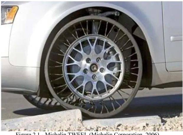
The IWS is a novel concept in suspension system design applicable to wheelchairs, bicycles, motorcycles, automobiles, trucks, and even airplane landing gears. Previous experimental studies at the University of Waterloo on wheelchairs has shown a tremendous improvement in the level of vibration and comfort in wheelchairs and also a good potential for the IWS concept to become a strong alternative to conventional suspension systems in other applications (Khajepour, 2007). In addition to the studies at the University of Waterloo, there have been other efforts to design flexible isolating wheels. Some of these designs are reviewed in this section. Most of these designs focus on replacing the inflatable pneumatic tire with a flexible maintenance free wheel. Michelin's TWEEL is the first non-pneumatic tire announced. Figure 2.1 shows Michelin's TWEEL.
Figure 2.1 - Michelin TWEEL (Michelin Corporation, 2006)
TWEEL is a revolutionary non-pneumatic wheel first announced by Michelin in 2005. TWEEL consists of a solid inner hub which mounts to the axle. The hub is enclosed by polyurethane spokes arrayed in a pattern of wedges. The outer edge of the tire, the part that contacts with the road, is formed by stretching a shear band across the spokes. The strength of the spokes combined with the tension of the shear band replaces the air pressure of a traditional tire. Although no specific data is given by Michelin on the mechanical properties and performance of TWEEL; vibration, noise, and heat generation are known as the shortcomings of TWEEL at higher speeds.
[image:2.612.158.468.370.599.2]Figure 2.2 - NASA mars rover wheels (National Aeronautics and Space Administration (NASA)
The low temperature, lack of atmosphere, and also weight restrictions prevent the use of inflatable rubber tires in projects like the Mars rover. The designed mars rover wheel is about 10" in diameter and is cut out of a solid piece of aluminum. Radial flexible aluminum spokes are designed to isolate the sensitive electronic equipments on the rover from excitations caused by moving on the rough surface of Mars. The outer surface of the wheel is anodized or covered with a black coating for additional strength. The steering and traction mechanisms are placed inside the wheel and are protected from possible external debris with an open-cell foam called Solimide (Evonik Industries) which remains flexible at low temperatures. Although the Mars rover wheel is designed to isolate the rover from undesirable excitations, yet there is no data on the performance and mechanical response of the wheel officially published by NASA.
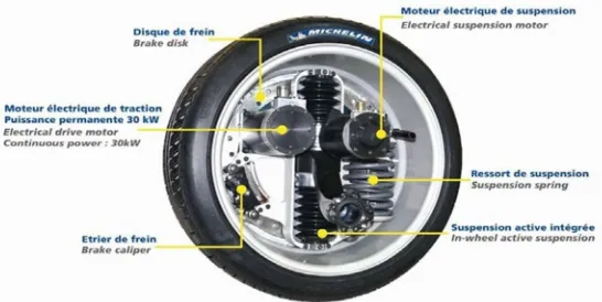
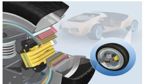
In addition to the rotating isolating wheels, Michelin and Siemens have announced wheels with non-rotating suspension components placed inside them. Michelin active wheel (Michelin re-invents the wheel, 2008) and Siemens eCorner (Continental Automotive Systems Inc.) are shown in Figure 2.3 and Figure 2.4. The Michelin active wheel integrates an electrical motor, the power-train, the suspension system, and the braking system inside the wheel. Likewise, Siemens VDO's eCorner concept embeds an automobile's drive-train, shock absorbers, brakes, and steering, into its four wheels. The eCorner removes the need for the traditional engine architecture. Siemens declares "The transition from an internal combustion engine to an eCorner wheel hub motor will result in decreased emissions, increased energy efficiency and lower costs for consumers due to the elimination of hydraulic systems to maintain and service." (Continental Automotive Systems Inc.).
Although the Michelin and Siemens wheels embed different automobile subsystems, including the suspension system, inside its wheels, but the suspension system is still limited to isolation in the vertical direction. However, adding an additional degree of freedom to the suspension system of a high-speed automobile requires more in-depth studies and considerations which are beyond the scope of this thesis.
[image:3.612.171.444.561.698.2]Figure 2.4 - Siemens' eCorner (Continental Automotive Systems Inc.)
Based on the presented a survey of some of the researches for using the available space inside a vehicle's wheel. This place is used for placing useful parts such as suspension components, steering mechanisms, and even the power-train. However these researches are still in the primary stages, and there is no precise performance data or design guidelines presented. In the following chapters the practicality and performance of placing a suspension system inside a vehicle's wheel is studied in more detail.
III. INVESTIGATION OF THE DYNAMICS OF AN IN-WHEEL SUSPENSION
A. Introduction
Since the first introduction of suspension systems on automobiles in 1903 by Mors (Jain, et al., 2002), almost any vehicle is equipped with one. The suspension system is usually a spring-damper subsystem isolating the passenger from wheel excitations. Momentary loads from ground are absorbed and damped out by the suspension system. Tires are also part of the suspension system absorbing high-frequency excitations. Although, existing suspension systems can effectively reduce the transferred shocks in the vertical direction, yet the isolation of the shocks emerging from horizontal excitations has remained unsolved.
The in-wheel Suspension System (IWS) will address the technical deficiencies in existing suspension designs by providing more comfort. It can effectively isolate shocks and road disturbances in any direction in the plane of rotation. In addition to extra comfort, it provides added passenger safety, reduced power consumption and solid tire manufacturing opportunities in many applications. This chapter presents a dynamics study of an IWS which was designed for a wheelchair at the University of Waterloo (Khajepour, 2007). The design was originally based on static calculations. This chapter’s objective is to evaluate the previously designed suspension for dynamics responses and investigate the effects of various parameters such as working speed, suspension stiffness, etc.
[image:4.612.221.390.551.697.2]B. Model Description
Figure 3.1 shows a schematic model of the wheelchair's IWS. The system consists of a planar mechanism with eight moving bodies:
Figure 3.1 - Schematic model of RPS for manual wheelchairs
l
The suspension system's mechanical properties are shown in Table 3.1.
Table 3.1 - Parameter values
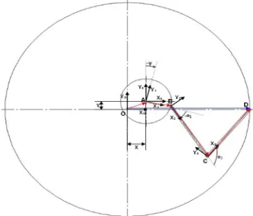
The mechanism has four degrees of freedom, where one of the degrees of freedom (the Rim’s rotation) is driven by a motor which specifies the operating speed of the wheel. A set of four independent variables is adequate to fully define the model; however, it is more convenient to use ten dependent variables and six constraint equations. The ten variables are shown in Figure 3.2:
X: The horizontal displacement of the center of the hub with respect to the ground
Y: The vertical displacement of the center of the hub with respect to the ground
Ψ: The angular displacement of the hub with respect to the rim
Ω: The angle of rotation of the rim with respect to the ground
ө1,3,5: The angles between the hub and the connecting arms
ө2,4,6: The angles between the connecting arms
The six constraint equations can be found by the following vector equation:
OD =OA+ AB+ BC+ BD
Giving two scalar equations for each set of connecting arms, for three sets of connecting arms six constraint equations are defined. These constraint equations are actually imposed by the joints between the arms and the rim (D in Figure 3.2).
There is also another constraint equation which is imposed by the driver connected to the rim:
t
Where ω is he angular speed of the motor
Figure 3.2 - Reference frames and variables
C. Applying Castigliano's Theorem to Spring Design
A general shaped planar spring can be considered as a beam with a constant or variable cross section subject to an in-plane force vector. As springs are usually designed within the elastic range of the material, Castigliano’s theorem can be used to simulate their behavior. However, it should be noticed that, in addition to the elastic behavior of the spring, the pure bending assumption requires the spring to be thin otherwise shear forces should be considered as well. Moreover, the solution may not be precise for large deformations as non-linear geometry effects are neglected.
Parameter Value
K 20 N.m/rad
C 4 N.m.s/rad
Ф 90o
R 50 mm
R 240 mm
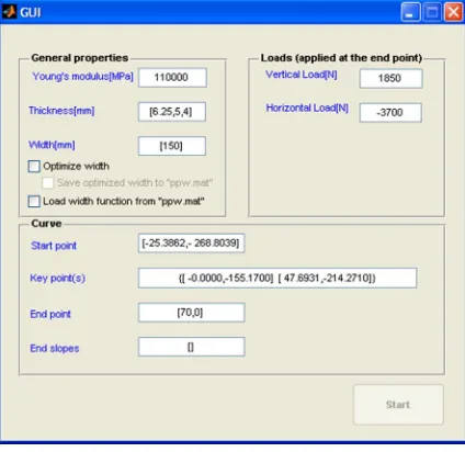
[image:5.612.233.415.474.629.2]The implementation of Castigliano's theorem requires calculation of the spring's strain energy. Using equation (3.8) to calculate the spring's strain energy requires the beam's bending moment (M), and cross-section properties (I) to be defined as a function the beam's length (x). To do so, a MATLAB code is developed which inputs the spring as a series of defining key points. Figure 3.3 shows a screen capture of the code's GUI. The spring's geometry is defined by a starting key point (Start point), followed by a series of key points (Key point(s)), and finally a key point at the end of the spring (End point). The code passes a cubic Spline through the key points. The sloped at the beginning and the end of the spring can be defined too (End slopes). Figure 4.3 shows a schematic view of a sample spring. The cross section properties, thickness and width, can be defined as a constant value for the entire length of the spring or with different values at each key point which will be linearly interpolated for the rest of the spring’s length.
Figure 3.3 - Castigliano spring design GUI
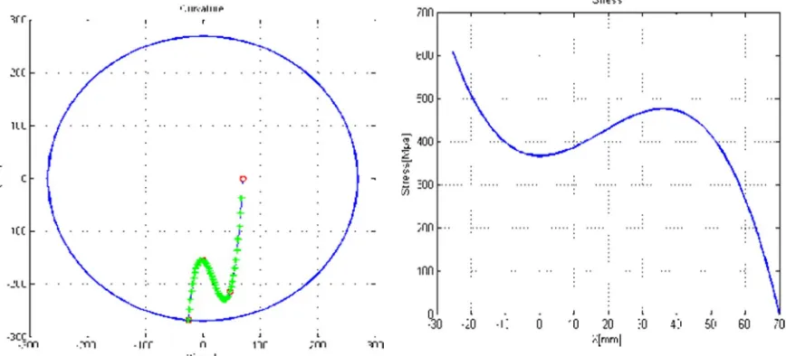
The program then uses the analytical polynomial definition of the spring to calculate the bending moment, and section properties along the beam's length. Accordingly, equation (3.8) is used to integrate the strain energy along the spring. The integrating points for a sample spring are shown in Figure 3.4. Finally, the strain energy is partially differentiated to find the deflection at the spring’s end point. The stress distribution can also be calculated at each section of the beam, using the following equation:
= /
Where:
σ = the maximum stress at each section
c= half of the section height at the desired point (t/2)
As the stress at each point of the spring is linearly related to the section width at that point, the program can optimize the section width along the spring to achieve a spring with a relatively constant stress distribution.
[image:6.612.179.406.560.719.2]MATLAB’s optimization functions such as fminmax can be used to optimize the shape of the Castigliano spring to design a spring with a specific stiffness. Figure 3.5 shows a sample spring inside a wheel's rim. The graph on the right shows the spring's equivalent stress. A simple proof of concept for a non-rotating in-wheel suspension system is designed using the code (Figure 3.6). The design consists of four pivot joint springs and two cantilever springs. Four pivot joint springs are used instead of two to achieve a symmetric design and also to increase the capability to handle out of plane forces. The cantilever springs are added to the design to boost the horizontal stiffness of the design. Although, the Castigliano method can be used to design and optimize springs for the IWS, but analytical integration and solutions takes a long time in comparison to FEA methods. Moreover, the model is constrained to analytically shaped springs with small deformation; however, one of the objectives of a suspension spring is to provide as much as wheel travel as possible. To overcome these restrictions, a more advanced spring optimization tool developed in the next section.
Figure 3.5 – Sample suspension spring and its stress levels
Figure 3.6 - Proof of concept design
IV. PROTO TYPING AND TESTING
The first design is a single part, fixed joint design, optimized for a proof of concept prototype and the second design is a practical flexible wheel with revolute joint springs designed for a manual hand- truck.
A. Fixed Connection Design
Fixed joint in-wheel suspension system is the simplest IWS design and is an ideal design for applications such as baby strollers, bicycles and gulf carts. The suspension is a single part which can be extruded with the wheel's hub and rim.
[image:7.612.125.439.460.618.2]B. Design Criteria
As a proof of concept design, the fixed joint prototype should demonstrate the practicality and simplicity of IWS. Thus, a soft, retrofit and easy to manufacture design is required. The fixed joint wheel prototype is intended to fit ordinary utility hand trucks; however, the load capacity is designed to be lower than the nominal 250lbs per wheel of hand trucks to emphasize the isolation capability and effectiveness of IWS. The overall dimensions and design targets of the fixed joint IWS are shown in Table 4.1.
Table 4.1 - Design criteria for fixed joint prototype
Parameter Value
Nominal load 200N(45lbs) per wheel Maximum load 400N(90lbs) per wheel
Stiffness 30N/mm
Wheel travel 15mm
Overall diameter 8"
Hub diameter 1.85"
Tread width 2"
C. Material Selection
DuPont Delrin 100 is selected as building material for the fixed joint prototype. Delrin is initially chosen because of its good machining properties and availability. However as it is discussed in section5.3.2, in addition to good machining capabilities, Delrin also has superior mechanical properties for a spring material. It has a metal like stress strain curve with a wide range of elastic behavior, high potential for storing elastic energy, high fatigue stress limit and also relatively stable mechanical properties at higher temperatures.
D. Optimization
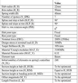
[image:8.612.182.433.467.734.2]At the time the fixed joint prototype was optimized, the optimization code was not as sophisticated as described in chapter 4. The code optimized the section height at only two locations: at the hub and the spring's midpoint; the spring's section height at rim was set equal to its section height at hub Modeling with plane or shell element was not supported either; however as the section height for a fixed joint design is thinner than that of a spring with revolute joints, Beam elements can be used with sufficient accuracy and less simulation time. Table 4.2 shows the design variables and optimization parameters used for optimizing the wheel. The optimization results are displayed in Table 4.3
Table 4.2 - Design criteria for fixed joint wheel prototype
Value
Hub radius (R_H) 22mm
Rim radius (R_R) 90mm
Spring width (B) 40mm
Number of spokes (N_SPK) 7
Spline end slop at hub (SLP_H) 90o
Spline end slope at rim (SLP_R) 90o
Hub vs. rim rotation angle (PHI)
0o
Hub joint type Fixed
Rim joint type Fixed
Nominal force (FRC) 200N (250lbs)
Design stress at nominal load (S_D) 30MPa
Target Stiffness (K_D) 30N/mm
Material Young's modulus (MAT_E) 3100MPa
Material Poisson ratio (MAT_V) 0.35
Element type Beam
Initial number of elements on spring's centerline (N_EL)
240
Section height at hub (H_HUB) To be optimized
Section height at rim (H_RIM) Equal to H_HUB
Section height at bending point (H_MID) To be optimized
Offset magnitude (M_V) To be optimized
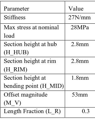
Table 4.3 - Optimization results
Parameter Value
Stiffness 27N/mm
Max stress at nominal load
28MPa
Section height at hub (H_HUB)
2.8mm
Section height at rim (H_RIM)
2.8mm
Section height at bending point (H_MID)
1.8mm
Offset magnitude (M_V)
53mm
Length Fraction (L_R) 0.3
E. Design finalization, CAD, Prototyping, and Testing
[image:9.612.238.393.382.516.2]Further details such as, detailed hub and rim designs, bearing housings and rubber tread are required to convert the optimized spring solution to a practical wheel. Figure 4.1 shows a solid model prepared in SolidWorks. The prototype is made of a solid Delrin disc which is first machined to create the hub and rim details. Then the extra material is removed by water-cutting. As it seen in Figure 5.1, three rubber O-rings are fitted on the rim to perform as the rubber tread. Although the isolation and grip of the O-rings are less than those of a rubber tread but this design avoids the complicacy of molding rubber over the Delrin wheel in the proof of concept prototype.
[image:9.612.187.425.614.709.2]Figure 4.1 - CAD model for fixed joint prototype
Figure 4.2 displays a manufactured fixed joint prototype. Prototypes are also sent to the project's industrial partner for experimental tests on hand trucks and evaluation of mechanical properties. Figure 4.3 displays the designed prototype installed on a hand truck. The hand truck is loaded with 130lbs and driven over and dropped off street curb. Figure 4.3 shows the instant that the loaded hand truck is dropped off a curb. The photo demonstrates the performance of the IWS and the shock absorbance and flexibility of the structure is apparent.
Figure 4.3 - The prototype installed on a hand truck
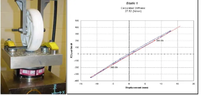
[image:10.612.134.475.326.488.2]In addition to the hand truck test, the prototype is also investigated for mechanical properties at Cooper-Standard Co. Figure 4.4 shows the test setup and test results from Cooper-Standard Co. As it is seen from the graph, the overall stiffness of the wheel is 27.52N/mm which shows less than 2% of error between the optimization and experimental results.
Figure 4.4 - Test setup and results from Cooper-Standard Co.
F. Fixed Joint Design for Baby stroller
Low working speed, low load and also relatively large wheels make baby strollers a good candidate for IWS application. Figure 4.5 shows a CAD model designed for a baby stroller. The studied " front wheel. The nominal working load including the weight of the stroller is about 40Kg and the maximum load is 100Kg. The designed IWS has similar spring units in both rear and front wheels. The suspension system allows for 25mm of wheel travel from each side. The material used for optimization is Tecast Vekton® 6XAU nylon which is less expensive than Delrin and has the ability to be over molded with other polymers despite Delrin.
[image:10.612.63.542.604.711.2]G. Design finalization, CAD, FEA Modeling, Prototyping, and Testing
[image:11.612.83.512.165.341.2]The springs optimized in section 4.3 are implemented in a practical design to fit the hand truck without any modification. The design includes rigid aluminum rim and hub components and stainless-steel side plates. The side plates are bolt to the rim to hold the Delrin springs in place. Furthermore, the maximum wheel travel in unexpected load conditions is restricted to design limits by a stainless-steel stopper plate attached to the rim (Figure 4.6). Moreover, the outer surface of the rim is covered with rubber for a better grip and isolation. Detailed drawings for the designed prototype are given in Appendix B.
Figure 4.6 - CAD model for revolute joint hand truck prototype
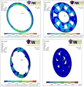
All of the components are also modeled in ANSYS to ensure Magline test requirements are met. The tests include static vertical and lateral maximum load, and also dynamics vertical and oblique drop tests. Figure 4.7 shows the FEA models for some of the components.
[image:11.612.167.441.425.707.2]1
0. 8
1st cycle
‐ ‐
0
‐0.2 0
1 2
‐0.6
[image:12.612.179.423.147.299.2]The prototyping procedure is followed by machining a single spring out of Delrin and testing it for static stiffness (Figure 4.8). The spring is also tested for its behavior in different temperatures. The results show less than 10% of stiffness change at 40oC and about 25% at 60oC. Furthermore, a fatigue test is done to check the durability of the spring. Figure 4.9 shows two cycles of the fatigue test at the 1st and 5000th cycles. The graph demonstrates the constant behavior of the spring. The fatigue test was continued for 2.5 million cycles and the spring lasted without any visible signs of mechanical failure at the nominal 9mm of wheel travel.
Figure 4.8 - Test setup and results for a single Delrin spring
[image:12.612.179.405.386.716.2]After verifying the optimization results with a single spring prototype, a whole wheel prototype is built. The manufactured prototype is shown in Figure 4.10. As it is seen from the pictures, a groove is also added to the wheel's hub allowing the insertion of a cotter pin. This cotter pin required by the hand truck manufacturer for fixing the wheel on the hand.truck's shaft.The built prototype is tested at the University of Waterloo’s high-pressure laboratory. The test setup and results are shown in Figure 4.11
Figure 4.9- Fatigue test
Figure 4.10 - Built hand truck wheel prototype
0. 35
0. 3
0. 2 5
25 Deg
y = 0.030x
40 Deg
y = 0.028x
0
0 5 1 1
Figure 4.12 shows the test results for static and dynamics loadings. The static stiffness of the prototype is measured to be 136N/mm (target: 135 N/mm, optimization result: 129N/mm). The prototype is also tested for the dynamics loading requirements specified by Magline. The wheel is tested for 50,000 cycles at 300, 400 and 500lbs loads. The prototype has passed the tests without any signs of mechanical failure to the springs or rigid components. Figure 5.16 also shows one of the cycles of the dynamics loading tests. The hysteresis effect visible in the graph is due to the friction at the revolute joints and also the structural damping effects of the flexible components.
Figure 4.11 - Test setup for the hand truck wheel
Figure 4.12 - Static (left) and dynamics (right) test results
V. CONCLUSIONS AND FUTURE WORKS
A. Conclusions
First, a mechanism based IWS which was previously designed for a wheelchair by static methods was investigated for dynamics response in Chapter 3. The dynamics simulations demonstrated the influence of different design parameters on the IWS. The results from Chapter 3 showed the feasibility of designing a rotating suspension with a linear stiffness rate and minimal fluctuations. The results also concluded that a rotating suspension system's performance is undermined at higher speeds. Moreover, the effectiveness could be improved by reducing the mass of the suspension's rigid links.
Afterwards, replacing the rigid suspension components with flexible structures was studied. This was done using energy and finite element methods in Chapter 4. The studies in chapter 4 conducted to the development of a spring optimization program. The developed interface can be used to optimize general two-dimensional springs for an IWS through a graphical user interface in MATLAB. The spring optimization tool developed in Chapter 4 was then verified by optimizing, building, and testing of two prototypes in Chapter 5. Experimental results verified the simulation results with less than five percent of error.
1. 5
1
0
‐
10 ‐ 0 10
0.5
‐ 1
B. Future Works
The developed IWS shows the feasibility and practicality of the IWS concept. However, employing the current design in a commercial application requires further optimization and tuning. Moreover, this research has studied the simple case of a non-powered, rotating IWS for low speed vehicles; however future researches can be conducted on more complicated IWS designs such as powered applications and designs for road vehicles.
The main challenge in the powered rotating in-wheel suspension design is achieving infinite rotational stiffness in addition to the requirements of a non-powered IWS. In a rigid mechanism design, the rotational stiffness can be attained by using parallel mechanisms. However, maximizing the rotational stiffness for a compliance design is a more significant challenge.
REFERENCES
[1] National Aeronautics and Space Administration (NASA). Wheels in the Sky. National Aeronautics and Space Administration (NASA) Web site. [Online] [Cited: June 1, 2009.] http://marsprogram.jpl.nasa.gov/mer/spotlight/wheels01.html.
[2] BASF Corporation. 2007. CAMPUS (Computer Aided Material Preselection by Uniform Standards). Frankfurt: CWFG (Chemie Wirtschafts Foerderungsgesell schaft GmbH), 2007.
[3] Beer, Ferdinand P and Johnston Jr., E. Russell. 1985. Mechanics of Materials. s.l. : McGraw-Hill Inc., 1985. ISBN 0-07-548578-8. [4] Composite integrated rear suspension. Morris, CJ. 1986. s.l. : Comp Struct, 1986, Vol. 5, pp. 233– 242.
[5] Continental Automotive Systems Inc. Siemens VDO's by-Wire Technology Turns the eCorner. [Online] [Cited: June 11, 2009.] http://usa.vdo.com/press/releases/chassis-and- car body/2006/SV_20061016_i.htm.