Copyright © 2012 IJECCE, All right reserved
Mathematical Modelling and Simulation Analysis of
Brushless DC Motor by using SIMULINK
G.Prasad
Department of Electrical and Electronics Engineering, GIT,
GITAM University, Visakhapatnam, 530045,
Andhra Pradesh, India. [email protected]
N.Sree Ramya
Department of Electrical and Electronics Engineering, GIT,
GITAM University, Visakhapatnam, 530045,
Andhra Pradesh, India.
Dr.P.V.N.Prasad
Department of Electrical Engineering, College of
Engineering, Osmania University, Hyderabad, Andhra
Pradesh, India
Dr.G.Tulasi Ram Das
Department of Electrical and Electronics Engineering,
College of Engineering, JNTUH, Hyderabad, Andhra
Pradesh, India
Abstract — The paper presents a model of three phase star
connected brushless dc motor considering the performance of motor during commutation. This process is done in SIMULINK after development of the BLDC motor with sinusoidal and trapezoidal waveforms of back-EMF. A comparision between the SIMULINK models of sinusoidal back-EMF and trapezoidal back-EMF is given.
Keywords – BLDC Motor, Electronically commutated motor, Back EMF, SIMULINK.
I.
I
NTRODUCTIONA motor that retains the characteristics of a dc motor but eliminates the commutator and the brushes is called a Brushless DC motor. Brushless DC (bldc) motors can in many cases replace conventional DC motors. They are driven by dc voltage but current commutation is done by solid state switches i.e., the commutation is done electronically. BLDC motors are available in many different power ratings, from very small motors as used in hard disk drives to large motors in electric vehicles. Three phase motors are most common but two phase motors are also found in many applications. The BLDC motors have many advantages over brushed DC motors. A few of these are:
Higher speed ranges
Higher efficiency
Better speed versus torque characteristics
Long operating life
Noiseless operation
Higher dynamic response
The torque of the BLDC motor is mainly influenced by the waveform of back-EMF. The ratio of torque delivered to the size of the motor is higher, making it useful in applications where space and weight are critical factors.
Ideally, the BLDC motors have trapezoidal back-EMF waveforms and are fed with rectangular stator currents, which give a theoretically constant torque. However, in practice, torque ripple exists, mainly due to emf waveform imperfections, current ripple and phase current commutation. The current ripple result is from PWM or hysteresis control. The emf waveform imperfections result from variations in the shapes of slot, skew and magnet of BLDC motor, and are subject to design purposes. Hence, an error can occur between actual value and the simulation results. This paper attempts to compare various types of BLDC motor models with the trapezoidal and sinusoidal back-EMF waveforms. The simple motor model of a
BLDC motor consisting of a 3-phase power stage and a brushless DC motor is shown in Fig.1.
II.
C
ONSTRUCTION OFBLDC
The BLDC motor is also referred to as an electronically commutated motor. There are no brushes on the rotor and the commutation is performed electronically at certain rotor positions. The stator phase windings are inserted in the slots (a distributed winding), or can be wound as one coil on the magnetic pole. The magnetization of the permanent magnets and their displacement on the rotor are chosen in such a way that the back-EMF shape is trapezoidal. This allows the three-phase voltage system, with a rectangular shape, to be used to create a rotational field with low torque ripples. In this respect, the BLDC motor is equivalent to an inverted DC commutator motor in that the magnets rotates while the conductors remain stationary.
Fig.1. BLDC Motor Model
In the DC commutator motor, the current polarity is reversed by the commutator and the brushes, but in the brushless DC motor, the polarity reversal is performed by semiconductor switches which are to be switched in synchronization with the rotor position. Besides the higher reliability, the missing commutator brings another advantage. The commutator is also a limiting factor in the maximal speed of the DC motor. Therefore the BLDC motor can be employed in applications requiring high speed.
power supply. Next, the rotor position must be known at certain angles, in order to align the applied voltage with the back-EMF. The alignment between the back-EMF and commutation events is very important. In this condition the motor behaves as a DC motor and runs at the best working point.
III.
M
ATHEMATICALA
NALYSISModelling of a BLDC motor can be developed in the similar manner as a three-phase synchronous machine. Since there is a permanent magnet mounted on the rotor, some dynamic characteristics are different. Flux linkage from the rotor depends upon the magnet material. Therefore, saturation of magnetic flux is typical for this kind of motors. As any typical three-phase motors, one structure of the BLDC motor is fed by a three phase voltage source. The source is not necessarily to be sinusoidal. Square wave or other wave-shape can be applied as long as the peak voltage does not exceed the maximum voltage limit of the motor. Similarly, the model of the armature winding for the BLDC motor is expressed as follows:
Va = Ria + L (1)
Vb = Rib + L (2)
Vc = Ric + L (3)
Where,
L is armature self-inductance [H], R-armature resistance [Ω],
Va, Vb, Vc – terminal phase voltage [V], ia, ib, ic – motor input current [A], and ea, eb, ec – motor back-EMF [V].
In the 3-phase BLDC motor, the back-EMF is related to a function of rotor position and the rotor position and the back-EMF of each phase has 120o phase angle difference so equation of each phase should be as follows:
ea = Kwf( e) (4)
eb = Kwf( e 2 /3) (5) ec = Kwf( e + 2 /3) (6) Where,
Kw is back EMF constant of one phase [V/rad.s-1],
e -electrical rotor angle [o el.], - Rotor speed [rad.s-1],
The electrical rotor angle is equal to the mechanical rotor angle multiplied by the number of pole pairs p:
e = m (7)
Where
m is mechanical rotor angle [rad].
Total torque output can be represented as summation of that of each phase. Next equation represents the total torque output:
Te = (8)
Where,
Te is total torque output [Nm],
The equation of mechanical part is represented as follows:
Te – Tl = J + B (9)
Where,
Tl is load torque [Nm],
J – Inertia of rotor and coupled shaft [kgm2], B – Friction constant [Nms.rad-1].
IV. S
IMULINKM
ODEL OF THEBLDC
M
OTORThe Simulink model of the BLDC motor is shown in fig.2.
Fig.2. Simulink Model of BLDC Motor
Unlike a brushed DC motor, the commutation of a BLDC motor is controlled electronically. To rotate the BLDC motor, the stator windings should be energized in a sequence. It is important to know the rotor position in order to understand which winding will be energized following the energizing sequence. Rotor position is sensed using Hall Effect sensors embedded into the stator. Most BLDC motors have three hall sensors embedded into the stator on the non-driving end of the motor.
Whenever the rotor magnetic poles pass near the hall sensors, they give a high or low signal, indicating the N or S pole is passing near the sensors. Based on the combination of these three hall sensor signals, the exact sequence of computation can be determined.
The converter block was developed using the equations below:
Va=(S1)Vd/2 –(S4)Vd/2 (10) Vb=(S3)Vd/2 –(S6)Vd/2 (11)
Vc=(S5)Vd/2 –(S2)Vd/2 (12)
Copyright © 2012 IJECCE, All right reserved However, one electrical cycle may not correspond to a
complete mechanical revolution of the rotor. The number of electrical cycles to be repeated to complete a mechanical rotation is determined by the rotor pole pairs. For each rotor pole pairs, one electrical degree is completed. The number of electrical cycles/rotations equals the rotor pole pairs.
Detailed SIMULINK model of the BLDC motor is:
Fig.3. Detailed SIMULINK model of BLDC motor
The sinusoidal back-EMF is given as:
Fig.4(a). Sinusoidal model of the back-EMF
The trapezoidal back-EMF is given as:
Fig.4(b). Trapezoidal model of the back-EMF
V.
R
ESULTSFig shows results of simulation of a BLDC motor with the following parameters: Vd =30v, R=4.98Ω, L=5.05 mH, p=4, J= 15.7*10-6 kgm2, Kw=56.23*10-3 V/rad.s-1, T1=0.1 Nm. The load time is 0.15 s.
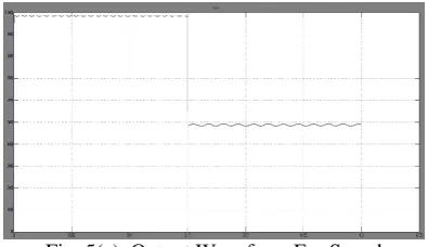
Simulations results for sinusoidal input: For speed:
Fig. 5(a). Output Waveform For Speed
For phi :
Fig. 5(b). Output Waveform For Phi
For Eabc :
Fig. 5(c). Output Waveform For Back EMF
For Iabc :
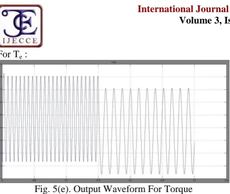
For Te :
Fig. 5(e). Output Waveform For Torque
For sinusoidal simulation model FFT analysis is given as:
For speed:
Fig. 6(a). FFT Analysis For Speed
For Eabc:
Fig. 6(b). FFT Analysis For Back EMF
For Iabc:
Fig. 6(c). FFT Analysis For Current
For phi:
Fig. 6(d). FFT Analysis For Phi
For Te:
Fig. 6(e). FFT Analysis For Torque
Simulation model for Trapezoidal input:
For speed:
Fig. 7(a). Output Waveform For Speed
For Phi:
Copyright © 2012 IJECCE, All right reserved For Iabc:
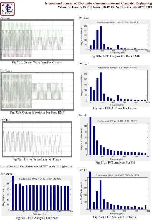
Fig.7(c). Output Waveform For Current
For Eabc :
Fig. 7(d). Output Waveform For Back EMF
For Te :
Fig.7(e). Output Waveform For Torque
For trapezoidal simulation model FFT analysis is given as:
For speed:
Fig. 8(a). FFT Analysis For Speed
For Eabc:
Fig. 8(b). FFT Analysis For Back EMF
For Iabc:
Fig. 8(c). FFT Analysis For Current
For phi:
Fig. 8(d). FFT Analysis For Phi
For Te:
Table1: Comparison of sinusoidal and trapezoidal outputs
Type of Wave form Sinusoidal Trapezoidal
Speed
Ripple factor 0.71 2.88
Peak value 988 492
THD 521.33 516.39
Torque
Ripple factor 0 0
Peak value 1.81 2.4
THD 520.13 543.71
Current
Ripple factor 0 0
Peak value
2 6.9
2 6
8 11
THD 361.28 351.99
Back EMF
Ripple factor 0 0
Peak value
28 13.5
28 13.5
28 14
THD 336.08 330.97
VI.
C
ONCLUSIONThe modelling procedure presented in this paper helps in simulation of various types of BLDC motors. The performance evaluation results show that such a modelling is very useful in studying the drive system before taking of the dedicated controller design.
R
EFERENCES[1] S. Baldursson, “BLDC Motor Modelling and Control – A MATLAB/Simulink Implementation”, Master Thesis, May, 2005.
[2] Padmaraja Yedamale, “Brushless DC (BLDC) Motor
Fundamentals”, Microchip Technology Inc., 2003.
[3] Ayetul Gelen, Saffet Asyasun, “Realization of Power Electronic Converter Based DC Motor Speed Control Method Using MATLAB/Simulink”, International Journal of Engineering Education, Vol.25,pp. 33-41,2009.
[4] B. Indu Rani, Ashly Mary Tom, “Dynamic Simulation of Brushless DC Drive Considering Phase Commutation and Backemf Waveform for Electromechanical Actuator”, IEEE TENCON 2008, Hyderabad.
[5] Balogh Tibor, Viliam Fedak, Frantisek Durovsky “Modelling and Simulation of the BLDC Motor in MATLAB GUI” IEEE paper 2011.pp 1403-1407 printed like “Modelling and Simulation of the BLDC Motor in MATLAB GUI” IEEE paper 2011
[6] Y.S. Jeon, H.S.Mok, G.H.Choe, D.K.Kim and J.S. Ryu, “A New Simulation Model of BLDC Motor with Real Back EMF waveforms”, IEEE CNF. On computers in Power Electronics, 2000. COMPEL 2000.pp. 217- 220, July 2000.
[7] Nagadeven Soib Taib, K S Rama Rao, DSP Based Sensorless Control of a BLDC Motor with Direct Back EMF Detection Method, International Conference on Control, Instrumentation and Mechatronics Engineering (CIM’07), Johor Bahru, Malaysia, May 28-29, 2007.
A
UTHOR’
SP
ROFILEG. Prasad
was born in the year 1976 in Jaggayyapet, Krishna Dist, Andhra Pradesh, India. He has received his B.E. degree in Electrical & Electronics Engineering from Andhra University, Visakhapatnam, India in 1999, and M.E. degree with Industrial Drives & Control from O.U College of Engineering, Hyderabad, India in 2006. He is presently working in the Department of Electrical & Electronics Engineering, GIT, GITAM University, Visakhapatnam. His areas of interest are Simulation of Electrical Machines & Power Electronic Drives. He has published/presented 13 technical research papers in national and international conferences and journals. He has 13 years of experience.
N. Sree Ramya
was born in the year 1989 in Kothagudem, Khammam Dist, Andhra Pradesh, India. She has received her B.Tech. degree in Electrical & Electronics Engineering from Jawaharlal Nehru Technological University, Hyderabad, India in 2010, and pursuing M.Tech. degree with Power Systems and Automation from GIT, GITAM University, Visakhapatnam, India.
P.V.N.Prasad
was born in Hyderabad, India in January 1960. He graduated in Electrical & Electronics Engineering from Jawaharlal Nehru Technological University, Hyderabad in 1983 and received M.E. in Industrial Drives & Control from Osmania University, Hyderabad in 1986. He served as faculty member in Kothagudem School of Mines during 1987 - 95 and at presently serving as Professor in the Department of Electrical Engineering, and Director, Information Dissemination Centre & Incharge, Diamond Jubilee Library,
UCEOU, Osmania University. He received his Ph.D. in Electrical
Engineering in 2002. His areas of interest are Simulation of Electrical Machines & Power Electronic Drives and Reliability Engineering. He is a member of Institution of Engineers (India) and Indian Society for Technical Education. He is recipient of Dr. Rajendra Prasad Memorial Prize, Institution of Engineers (India), 1993 - 94 for best paper. He has published over 63 papers in National and International Journals, Conferences & Symposia in the fields of Reliability Engg. and Electric drives. He has visited Thailand and Italy to present technical papers.