Research Journal
Volume 9, No. 26, June 2015, pages 113–117
DOI: 10.12913/22998624/2374 Research Article
Received: 2015.04.10 Accepted: 2015.05.08 Published: 2015.06.01
DETERMINATION OF TEMPERATURE IMPACT ON CMM RESIDUAL
KINEMATIC ERRORS DISTRIBUTION
Wiktor Harmatys1, Piotr Gąska1, Adam Gąska1, Maciej Gruza1, Jerzy Sładek1
1 Laboratory for Coordinate Metrology (M-10), Faculty of Mechanical Engineering, Cracow University of
Technology, Jana Pawła II 37, 31-864 Kraków, Poland, e-mail: [email protected]; pjgaska@gmail. com; [email protected]; [email protected]; [email protected]
ABSTRACT
In case of coordinate machines that use CAA correction matrix, the issue of kine-matic errors analysis may be based on the determination of residual error distribu-tion. Temperature changes have an impact on CMM kinematic structure, which may cause the differences in the map of residual errors. As for today, the residual errors were analysed only for the reference temperature. No research was undertaken on the residual errors changes depending on the temperature variations. This paper presents the experiment aimed at residual errors analysis and resulting errors distributions for different temperatures.
Keywords: residual errors, CMM correction.
INTRODUCTION
Today, in the era of continuous development of technology and industry, it becomes even more important to ensure adequate quality of manu-factured products. This task is entrusted to Co-ordinate Metrology which is an essential tool for quality control in modern companies. The biggest advantage of Coordinate Measuring Technique (CMT) is probably its versatility. Since informa-tion about the measured object geometrical fea-tures are obtained by determining coordinates of points on the object’s surface, one device can be used for many measurement tasks. The main tool of CMT is Coordinate Measuring Machine (CMM). In the CMMs the kinematic pairs can shift in mutually perpendicular directions, which determine the Cartesian axes x, y, z and defining the machine basic coordinate system. Thanks to utilization of different types of probing systems, measurements with CMMs may be automated. The unquestionable advantage of CMMs is their high accuracy and repeatability. The most precise machines offer accuracy up to tenths of a micron, and the works on machines that would be capa-ble of measuring in nanometres are in progress.
espe-cially those expressing the length which in turn leads to the variability of the CMM kinematic er-rors. Currently, at the Laboratory of Coordinate Metrology (LCM) the research are undertaken on the virtual machine which would take into consid-eration both of mentioned arguments. Developed at LCM virtual machine consists of two main modules: one responsible for machines kinemat-ics modelling and one devoted to probing sys-tems functioning. Distribution of residual errors is a basis for module responsible for kinematic errors modelling, it can be also used in determi-nation of the optimal position of measured object in the machine measuring volume [3]. The paper describes the experiment that involved determi-nation of residual errors distribution in different temperatures, in order to check the influence of temperature variability on kinematic errors. The obtained results as well as conclusions are also presented in the paper.
THE ERRORS RELATED TO CMM
KINEMATICS
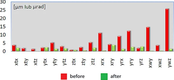
Machine’s kinematic errors are one of the main factors affecting the accuracy of any CMM. CMM kinematic errors were the subject of a num-ber of studies [4, 5] which resulted in the develop-ment of models of machine errors, for example full rigid body or reduced rigid body models. The most commonly used description of CMM geo-metrical errors include 21 components:
• positioning errors for each machine axis – xtx, yty, ztz;
• errors of mutual perpendicularity – xwy, xwz, ywz;
• translation errors – xty, xtz, ytx, ytz, ztx, zty; • rotation errors – xry, xrz, yrx, yrz, zrx, zry,
xrx, yry, zrz.
The geometrical errors defined in such a man -ner are a basis for operation of CAA (Computed Aided Accuracy) Matrix. The matrix itself as well as the methods of its determination are further de-scribed in [6]. The usage of this matrix has be-come a common practice, because it allows to cor-rect most of the errors components associated with the machine kinematic. The Figure 1 shows the values of individual components before (red bars) and after (green bars) the CAA matrix was used.
As it can be seen, some errors were almost completely corrected. The remaining errors in-clude both random errors and systematic errors that cannot be corrected or their correction would be unviable, namely residual errors. Since most of the currently used machines, utilize CAA cor-rection system, the issue of CMM kinematic error analysis can be transferred to the analysis of re-sidual errors. However, because the rere-sidual errors take into account the random errors components, they should be expressed rather by the probability distribution than certain values of error.
The residual errors distribution can be ex-pressed by assigning the standard deviations of points coordinate reproduction to chosen refer-ence points in measuring volume of machine. The standard deviations represent the probability of reference point reproduction. The exemplary dis-tribution of residual points is presented in Figure 2. The red arrows represent the standard deviation in scale 100000:1. All values are given in [mm].
EXPERIMENT AND RESULTS
The distribution of residual errors is a basis for operation of one of the modules of virtual ma-chine which is responsible for the kinematic er-rors modelling. Special methodology for residual errors determination was prepared at LCM for
Fig. 1. The geometrical errors before and after applying the CAA correction
the purpose of the developed virtual machine [7]. Residual errors are determined in chosen points which defines the reference grid. The required measurements are taken using LaserTracer sys-tem which uncertainty for spatial measurements can be expressed by the following equation: U = 0,2±0,3 · L/1000 μm. LaserTracer is a part of laser tracking devices family. It measures the distance to the target (retroreflctor) whose move -ments it follows. During measure-ments retrore-flector is mounted on the machine in the place of probe head. LaserTracer as a more accurate de-vice is used in order to check if machine indicate a correct coordinates of a reference point. The machine is programmed in such a way that retro-reflector approach to each node of reference grid from several directions (14 approach direction for each point) and then moves to the another grid
node. As the LaserTracer is able to measure only length, the multilateration method need to be used to determine the coordinate values. That means that the whole measuring sequence should be re-peated at least four times, each time placing the Laser Tracer in different position in CMM mea-suring volume. During all required measurements the CAA matrix installed on the machine have to be active. The described methodology was used to determine the residual errors distribution in dif-ferent temperatures.
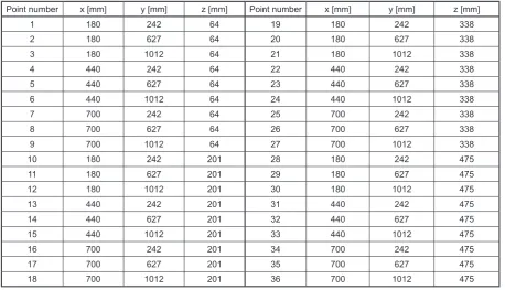
Measurements described in this paper were performed on the Zeiss WMM850S machine, lo-cated in the LCM at the Cracow University of Technology. This machine has a moving bridge, and it is characterized by measuring volume of 800\1200\700 mm. It is placed in the air-condi-tioned room, which allows temperature control. The three following temperatures for residual errors determination were chosen: 20±0,2 °C; 21±0,2 °C and 22±0,2 °C. The ambient condi-tions during all measurements were monitored using temperature sensors which were mounted in measuring volume of the machine and close to the scales corresponding to each axis. The read-ings from sensors indicate that the temperature during the test was within the specified range. The residual errors were determined in 36 ref-erence points distributed evenly in measuring volume of the machine. The grid nodes nominal coordinates are presented in Table 1.
Fig. 2. The example of distribution of residual errors distribution
Table 1. The grid of reference points
Point number x [mm] y [mm] z [mm] Point number x [mm] y [mm] z [mm]
1 180 242 64 19 180 242 338
2 180 627 64 20 180 627 338
3 180 1012 64 21 180 1012 338
4 440 242 64 22 440 242 338
5 440 627 64 23 440 627 338
6 440 1012 64 24 440 1012 338
7 700 242 64 25 700 242 338
8 700 627 64 26 700 627 338
9 700 1012 64 27 700 1012 338
10 180 242 201 28 180 242 475
11 180 627 201 29 180 627 475
12 180 1012 201 30 180 1012 475
13 440 242 201 31 440 242 475
14 440 627 201 32 440 627 475
15 440 1012 201 33 440 1012 475
16 700 242 201 34 700 242 475
17 700 627 201 35 700 627 475
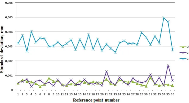
Fig. 3. Standard deviation of point reproduction in x-axis, for different temperatures
Fig. 5. Standard deviation of point reproduction in z-axis, for different temperatures
The obtained results are presented in Figures 3–5 which show the standard deviation of each point reproduction respectively in x, y and z axis for all three examined temperatures. Point num-bers correspond to the numeration from Table 1.
CONCLUSIONS
The obtained results indicate that changes in the temperature noticeably affects the residual er-rors derived from machine kinematics. The results obtained for the 22± 0,2 °C are characterized by not only the biggest values, but also the highest vari-ability, which reaches two micrometers. Also the results obtained for 21± 0,2 °C, show the consider-able volatility. The temperatures bigger than 22 °C are rarely met in measuring rooms even in indus-trial conditions so studies at higher temperatures are unnecessary. The further research need to be undertaken in order to verify if the similar results would be obtained also for the temperatures lower than reference temperature of 20 °C, what appears to be likely. If these suppositions are confirmed, it will mean that Virtual machines that could be suc-cessfully implemented in the industry should take into consideration thermal influences. In case of virtual machine developed at LCM that means that residual errors distribution (which is a base for a module that simulates the CMM kinematic errors) should be determined for different temperatures. The number of temperatures in which tests ought to be performed should be chosen on the basis of experience of measuring personnel which work with a specified CMM model.
Acknowledgements
Reported research was realized within con-fines of project financed by Polish National
Center for Research and Development No: LIDER/06/117/L-3/11/NCBR/2012.
REFERENCES
1. Trapet E., Franke M., Hartig F., Schwenke H., Wadele F., Cox M., Forbers A., Delbressine F., Schnellkens P., Trenk M., Meyer H., Morltz G., Guth Th., Wanner N.: Traceability of coordinate measuring machines according to the method of the Virtual Measuring Machines, PTB-F-35, Ger-many, Braunschweig, 1999.
2. Sładek J.: Modelowanie i ocena dokładności
maszyn oraz pomiarów współrzędnościowych. Praca habilitacyjna, Wydział Mechaniczny, Po -litechnika Krakowska, 2001.
3. Gąska A., Krawczyk M., Kupiec R., Ostrowska K.,
Gąska P., Sładek J.: Modeling of the residual kine -matic errors of coordinate measuring machines
us-ing LaserTracer system, The International Journal
of Advanced Manufacturing Technology, 73, 1-4, 2014, 497–507.
4. Trapet E. et al.: Traceability of coordinate mea-surements according to the method of the virtual measuring machine. Final report, European Com-mission SMT- EDG XII/C/5 Project No. Mat. 1 – CT94-0076.
5. Schwenke H., Knapp W., Haitjema H., Wecken-mann A., Schmitt R., Delbressine F.: Geometric error measurement and compensation of machines – An update. CIRP Annals – Manufacturing Tech-nology, 57, 2008, 660–675.
6. Gąska A., Gruza M., Gąska P., Karpiuk M., Sładek
J.: Identification and correction of coordinate mea -suring machine geometrical errors using Laser-Tracer systems, Advances in Science and
Technol-ogy Research Journal, 7, 20, 2013, 17–22.
7. Gąska A.: Modeling the accuracy of coordinate