*Corresponding author
Email address: [email protected]
1. Introduction
The increase in population in recent years has contributed to the progressive development of public transportation systems, trolley buses, trams, and light rail systems. Several factors, including the expansion of the rail network and the drop in voltage and energy losses, have led to many efforts to solve this problem. The energy losses of the components of the transportation systems are high and the energy consumption of the entire system are obtained by collecting the waste of its sub-sections. Hence, a new energy management method based on modern management approaches to minimize this waste of energy in transportation systems is needed [1]. New energy management techniques are available to control torque and reduce energy dissipation in motors through a new generation of electronic converters. In today's systems, due to the absence of bidirectional converters, electrical energy is lost in the resistors. With the
use of new energy management methods, energy storage through these methods should be planned to restore and provide energy.
Although the new energy management and control method can be used only when a train is in the acceleration mode while another train is simultaneously in the braking mode. The traffic conditions of rail lines that are not foreseeable are a very important factor in energy storage. The researchers' findings indicate that the maximum energy storage in accelerating mode can be up to ten percent [2]. Inverting substations is one of the researchers' proposed solutions to save energy for solving this problem [3-5].
The realization of this method imposes a lot of costs and forces us to make fundamental changes to the existing system architecture. Therefore, saving energy using the appropriate tools and using the modern management system in terms of energy and costs is a very reasonable method. [6-8].
Controlling Train Power Consumption with Energy Storage Based on Fuzzy Control - Case Study on Line 3 of Tehran Metro
Mohammad Ali Sandidzadeh1*, Tofigh Faizy1 , Farzaad Soleymaani1
1School of Railway Engineering, Iran University of Science & Technology
ARTICLE INFO A B S T R A C T
Article history:
Received: 28.01.2019 Accepted: 25.03.2019 Published: 15.06.2019
New high-speed trains need modern energy management methods to reduce energy consumption. In this research, a fuzzy based control method is proposed to solve this problem. The results are evaluated on the basis of data from Line 3 of Tehran Metro network. Recovering the maximum amount of train kinetic energy when it is in the braking mode and optimal conditioning of traction systems demand between energy storage system and power supply network, are the fundamentals of control strategy. In the control strategy the reference values of voltage and current of super capacitors (storage system) are calculated according to storage system state of charge and actual speed of train as optimal set points. The results from the modelling and simulations demonstrate that after applying the control strategy, optimization of energy consumption, optimal DC link voltage regulation and significant reduction in line peak current and power are achieved.
Keywords:
Electric Railway
Energy Storage System Fuzzy Control Strategy Super Capacitors Energy Consumption
40 International Journal of Railway Research (IJRARE) The energy storage devices that are mainly
used for railway applications are electrochemical batteries, flywheels, electric double layer capacitors (EDLCs). Some researchers have introduced the concept of hybrid energy storages, which combine more than one storage technology to exploit at the best the advantages given by each storage device. These energy storage devices have different purchase and maintenance costs and many differences exist in terms of functionality and performance, too. One of the factors to be taken into consideration is that the frequency of charge and discharge of energy storage devices has a significant impact on their lifetime. That's why it's a good idea to use super capacitors to solve this problem [9]. Energy storage in rail transport systems is generally performed by using wayside storages or storage networks in stations or mobile storages that in most cases it is installed on the roof of the train [10]. Each of the sub-sections saves energy independently, and finally all the energy is accumulated in the energy storage system but wayside and stationary storage devices as their name imply, are installed stationary and along the lines, respectively. Each system has its own advantages and disadvantages. Both Siemens and Bombardier companies are currently using this method [11].
Many non-railway projects have involved with energy storage in electrical equipment. There have been reasonable concerns for research in this area, as well. However, regarding energy storage only few projects were conducted in the rail transport systems. Because of the amount of the torque and the running speed of the motor in the rail transport industry that are vastly different from the other industries, the existing control methods that are used in many industries cannot be utilized in the railway sector [12].
Additionally, research on energy storage in various industries have not properly addressed the energy management issues. As a result, it cannot be stated that the available control methods can also be used in the railway industry.
In this research, the method of modern energy management is combined with the control strategies in the industry. The idea is to save energy and transfer it back to the network as much as possible.
The Fuzzy Control strategy is applied in this research to achieve the following selection of objectives:
1. Recover the maximum amount of kinetic energy during braking by train brake recovery technology
2. Optimum partition of Traction Systems power demand between application storage system and power supply network
In this control strategy the reference values of voltage and current of super capacitors (storage system) are calculated according to the state of charge of the storage system and the actual speed of the train.
The Fuzzy control strategy determines the maximum amount of the energy storage based on the train's speed and storage system state of charge to supply the traction system power. Since the load power demand (traction system inverter) is specified, the remaining required power for inverter traction will be supplied through the line by specifying the maximum storage requirement.
After designing and modeling the system, the simulation is carried out in Tehran metro line 3 to verify and check for the legitimacy of the results.
2. System Arrangement
Generally, the supply of train energy in interurban networks is through the overhead networks and is carried out though the metro via the third rail.
2.1. Electrical Traction Drive
Nowadays, with the recent advances in the design and implementation of traction systems, all types of tractions including AC or DC types with any range of voltages can be provided.The choice for the type of traction in a rail network depends on the homemade decisions and the available local standards. The Electric transmission lines for trains in rail networks are usually provided by one of two types of 0.75 kV or 1.5 kV DC systems. These two types are economically viable.
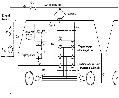
Figure 1 presents the power system and the typical electrical drive configuration on high-speed trains in metro lines. The energy storage system is also presented.
International Journal of Railway Research (IJRARE) 41
Figure 1.Typical electrical drive configuration
[9]
The Electrical multiple unit trains (EMU) are also surveyed in this research. It needs to be noted that this system is currently in use on Tehran Metro Line 3. The train gross weight is used for the calculations. With the inclusion of six engines and 2 wagons in the train makeup the train gross weight adds up to 408 tons. The maximum train speed is set at vt 80km h/ . The maximum train acceleration rate is 2
1 / a m s and the maximum braking deceleration rate is
2
1.2 /
d m s .
Each engine in the train makeup consists of asynchronous induction motors, whose energies are supplied by three-phase inverters. All inductive motors work on the same bogie.
The rail vehicle axles are driven by the corresponding induction motors through transmission systems that are mounted underneath the vehicles. The power supply voltage is750v and the size of the rail resistance per kilometer is at5.6m
km .
2.2. Energy Storage System
The energy storage systems are installed onboard the trains. These systems depend on the super capacitors and the number of power supply system inverters.
For the purposes of this research, the energy storage system contains six inverters. In other words, each one of the energy storage systems is connected to the inverter DC bus network by means of a DC to DC converter. When a high-speed train is in the braking mode, the kinetic energy is stored in the super capacitors that are embedded in the energy storage system. This
energy that is stored by the super capacitors will be used in the acceleration mode and this cycle will be continued.
3. System Modeling
For the system modeling and simulation all components including the load (train Inverter), lines, substations and storage system (Storage equipment and related DC-DC Converter) need to be included.
Modeling the electrical positions of the trains is performed by using their Thevenin equivalent circuit.
Assume vsubto be the source voltage,vline
the line voltage, rline the line variable resistance and iinvthe source current that supplied the inverters. At this stage the traction and the braking power can be calculated. By summing up these two terms of power with the power for the auxiliary equipment, the whole train inverter power; which can be a positive or negative is obtained.
inv inv
inv
p
i
v
(1)And the power drawn from the train or returned to the line is calculated according to the Equation (2).
, >0
, <0 t t
con t
el mech inv
t t el mech con t
Fv
P F
P
Fv P F
(2)
Where, vtis the actual train speed, Ft total is the traction effort,
el
em invis the electrical efficiency,
mechis the mechanical efficiency andcon
P indicates the required power for the other auxiliary equipment (ventilation, lighting, heating).
Figure 2 presents the behavior of the torque against the angular speed for a single traction motor. From this figure the parameter Pinvwhile considering(Tm v, ,m v, ) can be obtained.
42 International Journal of Railway Research (IJRARE)
Figure 2.Torque against angular speed for a single
traction motor [9]
Following on:
, sgn(F )
, 0 1
,
,max
(r r )
( )
(c 2 c u )
(0)
t sub sub line line inv
t line
line inv sto inv inv
inv sc sc ref
sto dcdc
inv
sc
sc ref sc
sc sc sc ref sc
sc sc
V i v
Rx r
L
i i i
P i
v
v i i
v
du i
dt
v r i u
u V
(3)
2
(m m ) t
t r t sc
t t
r t t
dv
F F
dt dx
v dt
F a bv cv
(4)
Taking into account that Nmis the number of
the traction motors, Rwheelthe radius of the driven wheel,
the transmission ratio,Tm v. is the torque of thevth
traction motor and m v, is the angular speed of the wheels.4. Fuzzy Control Strategy Design for Energy Storage System
Fuzzy control strategy determines the super capacitors (storage) maximum power for supply traction system power due to the actual speed of the train and the storage system state of charge. The control strategy block diagram is presented in Figure 3.
Figure 3.Control strategy block diagram
Due to the specified load (the traction system inverter) power demand, with specifies the maximum storage system power inverter traction, the remaining required power will be supplied through the line.
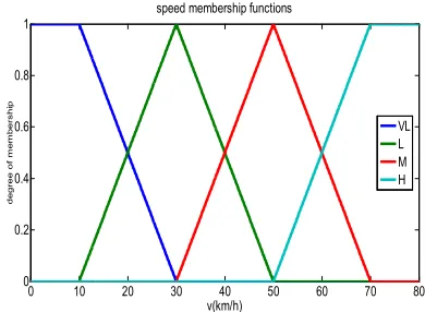
It should be noted that the train speedvtcan be measured by using an encoder that can be mounted on the engine shaft. The first step in any fuzzy system is the fuzzification of the inputs by the fuzzificator.
Figure 4.Fuzzy speed membership functions
The Fuzzificators that are used in this research paper are the triangular and the trapezoidal types.
Initially, it is needed to define the Membership functions input for the 0 10 20 30 40 50 60 70 80 0
0.2 0.4 0.6 0.8 1
v(km/h)
de
gree
of
m
e
m
b
ers
hi
p
speed membership functions
VL L M H
International Journal of Railway Research (IJRARE) 43
fuzzification. The Fuzzy system membership functions are presented in Figures 4 and 5.
Figure 5.Fuzzy state of charge membership
functions
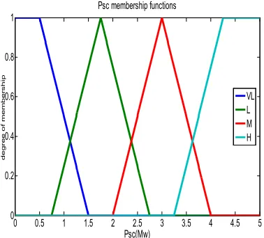
The Fuzzy output membership functions that are the super capacitors reference power are presented in Figure 6.
In order to insert the super capacitors in the proper operating conditions, the reference values of the voltage and the current set-point of the super capacitors (storage system) need to be defined.
Figure 6. Fuzzyoutput membership functions
At this stage, the set-point can be find by using the super capacitors reference power. Prior to this, the super capacitor reference voltage need to be set.
Table 1.SOC According to vt
SOC/ vt VL L M H
VL VL VL L L
L VL L L M
M VL L M M
H VL M M H
The basis for the energy saving is the brake energy recovery. The energy that is stored in the super capacitors from the initial voltage
max (0)
sc sc
u V to its final voltage charge is calculated as follows:
2 2 3 3
0 ,max 1 ,max
1
2
(V
u )
(V
u )
2
3
sc sc sc sc sc
E
c
c
(5)Due to the loss of the electrical energy, only a portion of the kinetic energy can be saved by the energy saving super capacitors. Hence, the following equations can be written:
2 2 3 3
0 ,max , 1 ,max ,
,max 2
1 2
(V u ) (V u )
2 3
1
(m )
2
sc sc ref sc sc ref
sc
t t
c c
E
k v
(6)
Where mt indicates the weight of the train. From the mathematical model, the super capacitors output power can be calculated as in Equation (7):
sc sc sc
P v i (7)
Then the super capacitor current set-point is given by the following Equation (8):
, .
, sc ref sc ref
sc ref
P i
u
(8)
To obtain a super capacitor reference voltage, the super capacitors current reference are compared with the actual current and the resulting error is processed by using a PI regulator. It will then result in vsc ref, according to the following Equation (9):
,
(i
,i )
(i
,i )
sc ref p sc ref sc i sc ref sc
v
k
k
dt
(9)0 10 20 30 40 50 60 70 80 90 100 0
0.2 0.4 0.6 0.8 1
SOC Percentage
de
gr
ee
o
f m
em
be
r
ship
SOC membership functions
VL L M H
0 0.5 1 1.5 2 2.5 3 3.5 4 4.5 5 0
0.2 0.4 0.6 0.8 1
Psc(Mw)
d
eg
re
e
of
m
e
m
be
r
shi
p
Psc membership functions
VL L M H
44 International Journal of Railway Research (IJRARE) By using Equation (9) the signal parameter
that is the PWM block duty cycle can be calculated according to Equation (10):
,
2(
sc sc ref) 1
inv
v
v
v
(10)In case when the upper switch is set to position ON, the signal
is set to 1. When the lower switch is set to position ON, the signal
is equal to -1.5. Numerical Results
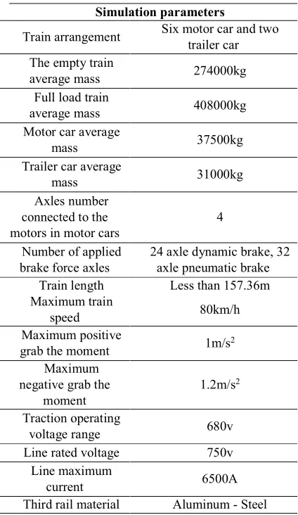
After running the simulation model the results are presented in Table 2. These results indicate that the control method that is used is appropriate. It can be used for the energy storage system on trains in the rail transport network.
Table 2.Simulation data parameters
Simulation parameters
Six motor car and two trailer car Train arrangement
274000kg The empty train
average mass
408000kg Full load train
average mass
37500kg Motor car average
mass
31000kg Trailer car average
mass
4 Axles number
connected to the motors in motor cars
24 axle dynamic brake, 32 axle pneumatic brake Number of applied
brake force axles
Less than 157.36m Train length
80km/h Maximum train
speed
1m/s2 Maximum positive
grab the moment
1.2m/s2 Maximum
negative grab the moment
680v Traction operating
voltage range
750v Line rated voltage
6500A Line maximum
current
Aluminum - Steel Third rail material
5.6 m /km
at 20 ° CThird rail electrical resistance per unit of
length
31 m /km
at 20 ° Ctrack rail electrical resistance per unit of
length
500-900v Line voltage range
500kw Auxiliary systems
average power
It should be noted that the simulated model based on the previous sections of this article is implemented and tested on the existing system in Line 3 of Tehran Metro. The energy storage system is the stationary super capacitor.
The results indicate that using this method for managing energy through fuzzy technique is effective. It can also be used in other rail networks.
As a case study, running a train between two stations in Line 3 of Tehran Metro is investigated. The track profile for this case study included:
The length of the first station (code A3-5): 220 meters without track gradient.
The length of the second station (code A3-6): 220 meters without track gradient.
The distance between the two stations: 1310 meters with a track gradient of 27/1000.
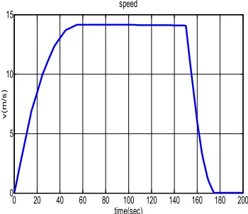
The speed profile that is used for the simulation along the route between the two stations is based on the actual data and is presented in Figure 7. The total running time for the process is equal to 175 s. The acceleration process is from time
t
0
till timet
45
s
.From t=45S to t=150S the train travels at a
constant speed. At t=150S the train braking
starts. The braking lasts for 25 seconds before the train stops. The maximum train speed in this process is 14.45m/s (52km/h).
Figure 8 presents the distance traveled by the train during the simulation. For the purposes of the simulation, the distance between the centers of the two stations is used and is equal to 1530m.
International Journal of Railway Research (IJRARE) 45
Figure 7.Output membership functions
Figure 8.Distance between the two stations
In the following, outputs for the electrical terms out of the simulation are discussed. The energy storage system performance must be such that in train acceleration it can supply the partial power demand of the traction system. While the DC link voltage regulation prevents voltage drop and prevents high line current consumption. In brake mode this system must recover and save the maximum recovered brake energy. It must also prevent the DC link voltage increases. The Metro system schematic with storage equipment has been shown in Fig 9.
The maximum current in the traction system appears during the acceleration times that in this case is equal to
t
25
s
here. At this instant the inverter required a current of 8.15kA to supply the traction system. Part of this current equal to 3kA comes from the supply line and the storage system provides the remaining 5.15kA. It is assumed that the storage system has the maximum initial charge. As presented in Figure 10, att
60
s
the storage system reached itsminimum charge, due to the governing conditions. From this moment the line supply total inverter current requirement is 5.46kA. At braking time
t
150
s
the maximum storage system recovery current is 12.9kA. The initial outcome of the installation of the storage control system is the reduction in the maximum line current.Figure 9.Train Schematic with power storage
devices [9]
The inverter current (power) at each instant is extracted form the line and the storage system current (power). The inverter, line and storage system current waveforms are presented in Figure 10.
Figure 10.Inverter, line, storage system and SC
current 0 20 40 60 80 100 120 140 160 180 200
0 5 10 15
time(sec)
v
(
m/s
)
speed
0 20 40 60 80 100 120 140 160 180 200 0
400 800 1200 1600
time(sec)
di
s
tance(
m
)
distance
0 20 40 60 80 100 120 140 160 180
-25 -20 -15 -10 -5 0 5 10
time(sec)
i(
K
A
)
inverter,line,SC,storage current
iline iinv isto isc
46 International Journal of Railway Research (IJRARE) Another important point that is presented in
Figure 10 is that the line current at the braking is reduced to zero. At this instant the line current is not null. This current is to overcome the resistance forces. From Figure 10 it should be noted that the storage system current is bidirectional. It’s DC-DC converter current and is different from the super capacitors current. The super capacitor current is presented with the black color curve in Figure 10. To detect the current for each super capacitor module one needs to consider that:
The maximum super capacitor current of 23.55 kA must be provided by 54 parallel modules. Therefore, the current for each module
is 23550 436.11
54
sc
i A.
Figure 11.Inverter, traction motor, line, storage system and SC power
The estimated power at different sections including the traction motor, inverter, main line, storage system and super capacitor are presented in Figure 11. The inverter maximum power is at 6.3 Megawatts. The storage system supplies 3.5Mw of it and the main line supplies the remaining. The power at the super capacitors and the storage sets are equal. This is due to the fact that the bidirectional DC-DC converter by the same proportion that reduces the super capacitor current increases the super capacitor voltage. It is also noticeable that there is inequality for power between the traction system and the inverter. This is due to the power required by the auxiliary equipment such as the ventilation, lighting, heating and cooling systems. There is
also power losses in the system that need to be accounted for.
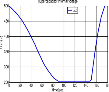
The energy flow diagram of the rail system is presented in Fig 12. From this the flow and the energy conversion and losses of various sectors is evident. The voltages at different system sections are analyzed. The super capacitor internal voltage that is calculated based on Equation (9) is presented in Figure 12.
Figure 12.Super capacitor internal voltage
Figure 13.DC voltage with and without storage
system
The super capacitors are discharged through DC to DC converters. There is also the possibility for the SOC to reach somewhere between the rated voltage value of
,max 500 sc
v v and its half.
During the acceleration process the super capacitor voltage increases and at deceleration it charges to vsc,max 500v .
0 20 40 60 80 100 120 140 160 180 -25
-20 -15 -10 -5 0 5 10
time(sec)
i(
K
A
)
inverter,line,SC,storage current
iline iinv isto isc
0 20 40 60 80 100 120 140 160 180 250
300 350 400 450 500
time(sec)
U
s
c
(
v
)
supercapacitor internal voltage
usc
0 20 40 60 80 100 120 140 160 180 700
720 740 760 780 800 820
time(sec)
v
ol
tag
e(
v
)
DC link voltage with & without storage system
vdc with sc vdc without sc
International Journal of Railway Research (IJRARE) 47
One of the advantages of the installation and control of the storage system is the DC link voltage regulation. For a better realization in the application of this system, the DC link voltage with and without the storage system are compared in Figure 13.
Without the storage system the DC link voltage drops from
810
v
(no load) to716
v
during the acceleration process. This is equal to 11.6% voltage drop. But with the storage system the voltage drop reduced to 7% (from
810
v
to750
v
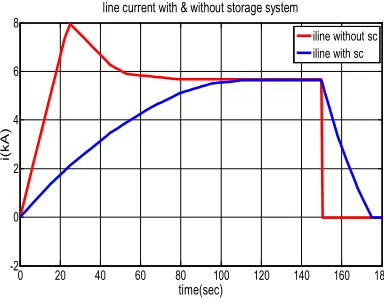
). This can be interpreted as 4.6% improvement in the DC link voltage drop. Figure 14 compares the main line current with and without the storage system.Figure 14.Line current with and without storage
system
From Figure 14 it is concluded that the line peak current reduces from 8kA at t 25s to
5.56kA. A significant reduction of 32%. The line peak current reduction not only reduces the energy consumption but also improves the basic parameters for the main line and substation design.
The energy consumption is also amongst the terms in focus. The purpose of the energy storage is to be able to recover and store the rail vehicle kinetic energy during its braking processes. The consumed and the supplied energy by various sections including the inverter traction energy, the traction motor energy (also known as the mechanical energy) and the main supply line and the storage system energy are presented in Figure 15.
The following points can be extracted from the information in Figure 15.
1. At
t
150
s
that is the braking start point, the traction inverter required energy is190
kwh
. The storage system supplies32kwhand the main line supplies
158
kwh
. This means that the storage system supplies 16.84% and the main line supplies 83.16% of the total energy requirement for the traction invertor. With the storage system the energy saving is 16.84%.2. The storage system energy diagram is proportional to the square of the train speed.
3. The storage system energy at the end of the motion cycle is equal to zero. This means that the storage system charges during the braking and discharges during the accelerating times.
Figure 15.Inverter, traction motor, line and
storage system energy
Figure 16.Line energy with and without the
storage system 0 20 40 60 80 100 120 140 160 180
-2 0 2 4 6 8
time(sec)
i(
kA
)
line current with & without storage system
iline without sc iline with sc
0 20 40 60 80 100 120 140 160 180 0
0.5 1 1.5
2x 10 5
time(sec)
energ
y
(wh)
inverter,Tr motor,line & storage system energy
Einv Emech Eline Esto
0 20 40 60 80 100 120 140 160 180 -2
0 2 4 6 8
time(sec)
i(kA)
line current with & without storage system
iline without sc iline with sc
48 International Journal of Railway Research (IJRARE) The estimated main supply line energy with
and without the storage system are compared at Figure 16. Without the energy storage system the main line is needed to supply all inverters energy requirements that is equal to
190
kwh
. With the storage system the energy consumption from the main supply line reduces to158
kwh
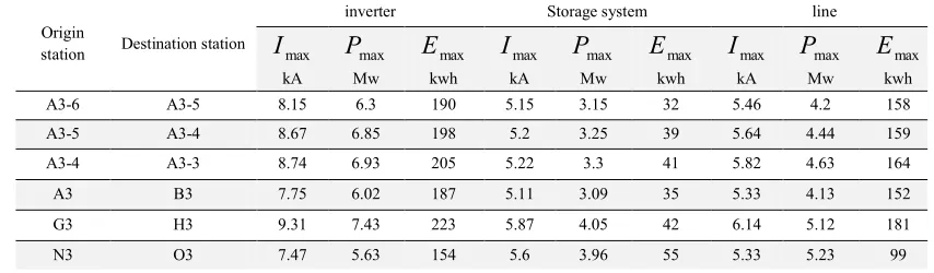
.All the above presented results involved the first and the second stations of the Line 3 of Tehran Metro network. In a further endeavor and on the basis of the same type of modelling, a variety of simulations were performed for a train running between some other stations in Tehran Metro network. The results are presented in Table 3.
6. Conclusions
This research presented the fuzzy control strategy for energy management of metro trains that are equipped with the super capacitor energy storage system. Due to the actual running speed of the train and the storage system state of charge, the fuzzy control strategy determines the super capacitors maximum power for supplying
the traction system power. The modelling and simulations performed on the Line 3 of Tehran metro network trains demonstrated that with the proper energy storage system installation and control, energy consumption reduction of 35% is achievable.
The usage of the energy storage systems on the trains have some other added advantages. Amongst them are up to 35% reduction in the main supply line peak current and power consumption that improves the basic parameters of the main line and the substation designs. It also regulates the DC link voltage to a significant percentage. In this case, without the storage system the DC link voltage drop is 11.6% but with the storage system the voltage drop is 7%.
The power storage system also enhances the system reliability.
References
[1] Siemens, Sitras SES, Stationary energy storage system for DC traction power supply [Online], (Nov. 2012), Available:
Table 3 (continued).The results of various simulations for a train running between different stations on
Tehran Metro network
Origin
station Destination station
inverter Storage system line
max
I
kA
max
P
Mw
max
E
kwh
max
I
kA
max
P
Mw
max
E
kwh
max
I
kA
max
P
Mw
max
E
kwh
A3-6 A3-5 8.15 6.3 190 5.15 3.15 32 5.46 4.2 158
A3-5 A3-4 8.67 6.85 198 5.2 3.25 39 5.64 4.44 159
A3-4 A3-3 8.74 6.93 205 5.22 3.3 41 5.82 4.63 164
A3 B3 7.75 6.02 187 5.11 3.09 35 5.33 4.13 152
G3 H3 9.31 7.43 223 5.87 4.05 42 6.14 5.12 181
N3 O3 7.47 5.63 154 5.6 3.96 55 5.33 5.23 99
Table 3.The results of various simulations for a train running between different stations on Tehran Metro
network
Origin
station Destination station
gradient (Per mill)
Optimization of energy consumption
(Percent)
Line peak current Reduction
(Percent)
A3-6 A3-5 1.96 16.84 32
A3-5 A3-4 2.74 19.69 35
A3-4 A3-3 2.9 20 31
A3 B3 -1.15 18.71 31
G3 H3 49.6 18.83 33
N3 O3 -31.02 35.71 32
International Journal of Railway Research (IJRARE) 49
http://www.mobility.siemens.com/ts/de/pub/40 4.htm
[2] B. Mellitt, Z.S. Mouneimne, C.J. Goodman, Simulation study of DC transit systems with inverting substations, IEE Proceedings B Electric Power Application, 131(2), (1984), pp. 38–50.
[3] Ch. Bae, D.U. Jang, Y.G. Kim, Calculation of regenerative energy in DC 1500V electric railway substations, In: Proc. of 7th Int. Conf. Power Electron. ICPE’07, Daegu, South Korea, October 22–26, (2007), pp. 801–805.
[4] V. Gelman, Braking energy recuperation, IEEE Vehicular Technology Magazine, 4(3), (2009), pp. 82–89.
[5] C.H. Park, S.J. Jang, B.K. Lee, C.Y. Won, H.M. Lee, Design and control algorithm research of active regenerative bidirectional DC/DC converter used in electric railway, In Proc. 7th Int. Conf. Power Electron. ICPE’07, Daegu, South Korea, October 22–26, (2007), pp. 790– 794.
[6] Y. Taguchi, M. Ogasa, H. Hata, H. Iijima, S, Ohtsuyama, Simulation results of novel energy storage equipment series-connected to the traction inverter, In: Proc. 12th Eur. Conf. Power Electron. and Applicat. EPE’07, Aalborg, Denmark, September 11–14, (2007), pp. 1–10. [7] D. Iannuzzi, P. Tricoli, Metro trains equipped onboard with supercapacitors: a control technique for energy saving, In: Proc. Int. Symp. Power Electron. Elect. Drives, Automation and Motion, SPEEDAM’10, Pisa, Italy, June 14–16, (2010), pp. 750–756.
[8] M. Miyatake, H. Haga, Optimization of speed profile and quick charging of a catenary free train with on-board energy storage, In: Proc. Int. Conf. Elect.Syst. for Aircraft, Railway ad Ship Propulsion ESARS’10, Bologna, Italy, October 19–21, (2010), pp. 1–6.
[9] D. Iannuzzi, F. Ciccarelli, D. Lauria, Stationary ultracapacitors storage device for improving energy saving and voltage profile of light transportation networks, Transportation Research Part C: Emerging Technologies, 21(1), (2012), pp. 321–337.
[10] Overview of braking energy recovery technologies in the public transport field, Ticket to Kyoto, WP2B. Deliv.1 http://www.tickettokyoto.eu/sites/default/files/d
ownload/file/T2K_WP2B_deliverable1_201105 20.pdf
[11] M. Steiner, M. Klohr, S. Pagiela, Energy storage system with ultracaps on board of railway vehicles, in Proc. 12th Eur. Conf. Power Electron. Appl. (EPE 2007), Aalborg, Denmark, Sep. 11–14, pp. 1–10.
[12] P. Grbovic, P. Delarue, P.L. Moigne, P. Bartholomeus, The ultra-capacitor based controlled electric drives with braking and ride-through capability: overview and analysis, IEEE Transaction on Industry Electronics, 58(3), (2011), pp. 925–936.