11
Copyright © 2018. IJEMR. All Rights Reserved.
Volume-8, Issue-4, August 2018
International Journal of Engineering and Management Research
Page Number: 11-15
DOI: doi.org/10.31033/ijemr.8.4.2
Transformer Parameters Monitoring System using MATLAB Simulink
Ashish C. Jangam1, Prof. D.G. Chougule2 and Prof. A.S. Mali3
1M. E. Student, Department of Electronics Engineering, TKIET, Shivaji University, Kolhapur, Maharashtra, INDIA 2Head, Department of Electronics Engineering, TKIET, Shivaji University, Kolhapur, Maharashtra, INDIA 3
Assistant Professor, Department of Electronics Engineering, TKIET, Shivaji University, Kolhapur, Maharashtra, INDIA 1Corresponding Author: [email protected]
ABSTRACT
Transformer is an important component of an electrical distribution system. Hence it is important to monitor transformers for problems before faults occur. This system is about design and implementation of embedded system to monitor and record key parameters of a distribution transformer like load currents,voltage and temperature. It is installed at the distribution transformer site and the above parameters are recorded using the analog to digital converter (ADC) of the embedded system. The obtained parameters are processed and recorded in the system memory. If any abnormality or an emergency situation occurs the system takes immediate action to avoid it. This system will help the transformers to operate smoothly and identify problems before any failure. proposed system is low cost, easy to use capable of monitoring and displaying data using matlab[1,6].
Keywords— Transformer, Sensors, Microcontroller,
MATLAB
I.
INTRODUCTION
In recent years, electrical power system is spread all over the world; hence there is transfer of large electrical power from generating station to the end users. Hence it is necessary to monitor the operating condition of distribution transformer when it is loaded. However, there life is significantly reduced if they are over loaded, resulting in unexpected failures and loss of supply to a large number of customers. Thus affecting system reliability. Distribution transformers are connected directly to the load side hence most of the possibility of fault is at distribution transformer due to sudden variation in load. Distribution transformers are currently monitored by manual monitoring does not gives current value of some parameters like overload current and overheating of
transformer. This factor can reduce transformer life. This paper deals with real time monitoring of transformer parameters to enhance its life[3].
II. TRANSFORMER FAULTS
1. Over Load
Over current is the current flowing through the transformer resulting from faults on the power system. Fault currents that do not include ground are generally in excess of four times full-load current; fault currents that include ground can be below the full-load current depending on the system grounding method. Over current conditions are typically short in duration (less than two seconds) because protection relays usually operate to isolate the faults from the power system. Overload, by contrast, is current drawn by load, a load current in excess of the transformer name-plate rating. In summary, loading large power transformers beyond nameplate ratings can result in reduced dielectric integrity, thermal runaway condition (extreme case) of the contacts of the tap changer, and reduced mechanical strength in insulation of conductors and the transformer structure. Three factors, namely water, oxygen, and heat, determine the insulation life of a transformer. Filters and other oil preservation systems control the water and oxygen content in the insulation, but heat is essentially a function of the ambient temperature and the load current. Current increases the hottest spot temperature (and the oil temperature), and thereby decreases the insulation life span[3].
2. Over Temperature
12
Copyright © 2018. IJEMR. All Rights Reserved.
over voltage and over current, temp. of oil increases whichcauses failure of insulation of transformer winding[3].
3. Over Exicitation
The flux in the transformer core is directly proportional to the applied voltage and inversely proportional to the frequency. Over excitation can occur when the per-unit ratio of voltage to fre-quency (Volts/Hz) exceeds 1.05 p.u. at full load and 1.10 p.u. at no load. An increase in transformer terminal voltage or a decrease in frequency will result in an increase in the flux. Over excitation results in excess flux, which causes transformer heating and in-creases exciting current, noise, and vibration[3].
III. PROPOSED SYSTEM
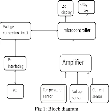
Fig 1 shows the block diagram of proposed system for monitoring of transformer parameters. The proposed system is based on microcontroller that monitors the voltage, current and temperature of a distribution transformer. These monitored parameters of distribution transformer will be display on pc. Monitored parameters are compared with the rated values of the transformer and microcontroller is programmed in such a way when the monitored values exceed the rated values it takes immediate action and displays the value on pc. The microcontroller is programmed in such a manner so as to continuously scan the transformer and update the parameters values at a particular time interval[2].
Fig 1: Block diagram
Fig 2 shows flowchart of proposed system. Flowchart defines operation of system.
Observations
1. Sensors are initialised to sense current, voltage & temperature of transformer.
2. Microcontroller continuously update & display readings on pc.
3. If transformer parameters such as current and voltage exceeds rated values microcontroller is programmed in such a way that it stops power supply.
4. If temperature parameter exceeds rated value microcontroller is programmed in such a way that it turns on cooling fan[1].
Fig 2: Flowchart
IV. HARDWARE IMPLEMENTATION
TABLE 1 Component specification
Sr.No
Component Specification quantity
1 Microcontroller PIC16F877A 1 2 Voltage
transformer
1 phase, 230/12V 2
3 Current transformer
1 phase, 0.25- 20 A
1
4 Temperature sensor
LM35(-55 to 150 celcius )
13
Copyright © 2018. IJEMR. All Rights Reserved.
1. PIC16F87XA
The main role of microcontroller is to check received information with the prepared program available inside the microcontroller; depending upon which several relays (i.e. devices) are operated. The microcontroller PIC 16F87XA is a High-Performance RISC CPU .It will provide only 35 single-word instructions. Its operating speed is DC-20MHz clock input which contains 8K x 14 words of Flash Program Memory, 368 x 8 bytes of Data Memory (RAM) & 256 x 8 bytes of EEPROM Data Memory. It contains three timers, three ports, USART with 9-bit address detection & Brown-out detection circuitry for Brown-out Reset. It uses CMOS tech. with Low-power, high-speed Flash/EEPROM technology& Low power consumption[4].
2. Voltage sensor
It is used to measure voltage in electrical power system. When voltage is too large to be conveniently used by an instrument it can be scaled downed to standardized low value. A voltage sensor is a device which detects the voltage in a wire, and generates signal proportional to it. The generated signal could be analog voltage or current or even digital output. It can be then utilized to display the measured voltage in a voltmeter or can be stored for further analysis[4].
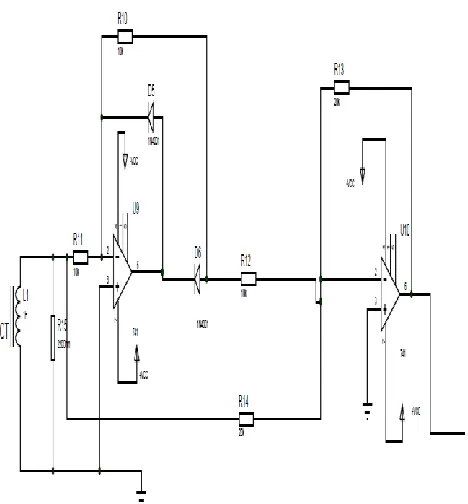
Fig 3: Circuit diagram of voltage sensor
3. Current sensor
Current sensor provides economical and precise solution for both DC and AC current sensing in industrial, commercial and communication systems. Typical applications include motor control, load detection and management, over-current fault detection and any intelligent power management system etc. A current sensor is a device that detects electric current (AC or DC) in a wire, and generates a signal proportional to it. The generated signal could be analog voltage or current or even digital output. It can be then utilized to display the measured current in an ammeter[4].
Fig 4: Circuit diagram of current sensor
4. Temperature sensor
Temperature Sensors measure the amount of heat energy or even coldness that is generated by an object or system, allowing us to “sense” or detect any physical change to that temperature producing either an analogue or digital output. The LM35 series are precision integrated-circuit temperature sensors, whose output voltage is linearly proportional to the Celsius (Centigrade) temperature. The LM35 thus has an advantage over linear temperature sensors calibrated in ° Kelvin, as the user is not required to subtract a large constant voltage from its output to obtain convenient Centigrade scaling. The LM35 does not require any external calibration or trimming to provide typical accuracies of ±1⁄4°C at room temperature and ±3⁄4°C over a full −55 to +150°C temperature range. Low cost is assured by trimming and calibration at the wafer level. The LM35’s low output impedance, linear output, and precise inherent calibration make interfacing to readout or control circuitry especially easy. It can be used with single power supplies, or with plus and minus supplies[4].
14
Copyright © 2018. IJEMR. All Rights Reserved.
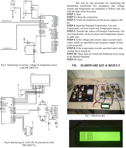
Fig 5: Interfacing of current, voltage & temperture sensorwith PIC16F877A
Fig 6: Interfacing of LCD, PC & relay driver with PIC16F877A
VI.
ALGORITHM FOR CENTRALISED
MONITORING
The step by step procedure for monitoring the distribution transformer key parameters like voltage, current and temperature are explained as follows and also with the help of the flowchart.
STEP 1: Start.
STEP 2: Check the connection.
STEP 3: Verify the hardware for the power supply to the kit.
STEP 4: Input the Potential Transformer, Cur rent Transformer, oil level sensor and Temperature Sensor. STEP 5: Transfer the values of Potential Transformer, Cur rent Transformer, oil level sensor and Temperature Sensor to ADC port.
STEP 6: If the voltage and current values exceeds rated values which are specified in pic program, supply of load is disconnected.
STEP 8: If the temperature exceeds specified rated value, cooling fan is turned on.
STEP 10: These data are stored and displayed on pc using in the Matlab Simulink.
STEP 12: Stop
VII. HARDWARE KIT & RESULT
Fig 7: Hardware Kit
15
Copyright © 2018. IJEMR. All Rights Reserved.
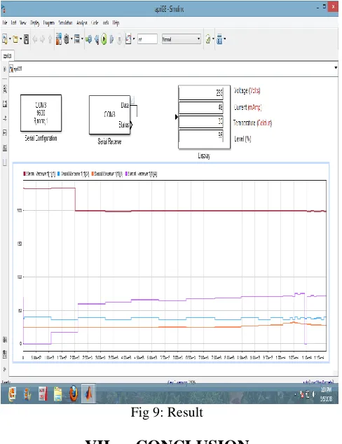
Fig 9: ResultVII. CONCLUSION
In this paper, the distribution transformer key parameters like voltage, current and temperature are monitored using PIC16F877A Microcontroller. Monitored parameters are transferred from the PIC Microcontroller to the PC. This system protects transformer from overloading and overheating. This system can control some major parameter of transformer so that it can be a good solution for transformer failure.
REFERENCES
[1]Sashank Shekhar, Somvanshi, & Dr. Deependra Pandey. (2017). A simulink based system to monitor parameters of transformer. International Journal of Innovative Research in Science, Engineering and Technology, 6(Special Issue-9), 51-54.
[2] V.A. Patil, Namrata S. Kumbhar, & Shital S. Patil. (2017). Transformer monitoring and controlling with Gsm based system. International Research Journal of Engineering and Technology, 4(3), 119-123.
[3] Vadirajacharya. K, Ashish Kharche, Harish Kulkarni, & Vivek Landage. (2012). Transformer health condition monitoring through gsm technology. International Journal of Scientific and Engineering Research, 3(12), 1-5. [4] Dr. J.Jayakumar, J. Hephjiba Jose Queen, Thanu James, G. Hemlata, & Neetu lonappan. (2013).
Distribution transformer monitoring using gprs.
International Journal of Scientific and Engineering Research, 4(6), 1199-1204.
[5] M. Banupriya, R. Punitha, B. Vijayalakshmi & C. Ramkumar. (2013). Power transmission monitoring system using zigbee. Global Journal of Researches in Electrical and Electronic Engineering, 13(16), 16-26.
[6] Pathak A. K, Kolhe A.N, Gagare J. T, & Khemnar S. M. (2016). Gsm based distribution transformer monitoring and controlling. International Journal of Advance Research and Innovative Ideas in Education, 2(2), 349-351.