IJEDR1804021
International Journal of Engineering Development and Research (
www.ijedr.org
)
112
Performance improving of active power filter in
microgrid system by using fuzzy controller
1
Shaila Chhatrabhuj jadkar,
2Varsha jain,
1Student, 2Assistant Professor, 1PG Control System,
1Collage Of Engineering Ambajogai, Ambajogai, India
_____________________________________________________________________________________________________
Abstract— In the distribution system load has been sudden changes and it is like a non-linear loads the use of nonlinear loads creates the problems in the power system such as load harmonics, reactive power and excessive neutral currents. This paper presents an Active Power Filter implemented with a four leg voltage source inverter using dq (synchronous reference frame) based current reference generator scheme is presented. the use of a four-leg voltage source inverter allows the compensation of current harmonic components and also unbalanced current generated by single phase non-linear loads. the grid interfacing can thus be utilized as i)power converter to inject generated power from rest of the grid, and ii)shunts APF to current unbalance, load current harmonics and load reactive power demand the compensation, performance of the active power filter using an fuzzy controller and the associated control scheme under steady state and transient operating condition is demonstrated through simulation results.
Index terms- Active power filter, Four leg converter, fuzzy controller, RES(renewable energy sources).
_____________________________________________________________________________________________________
I.INTRODUCTION
The lots of use of non-linear loads is leading to a variety of undesirable phenomena in the operation of power systems. The components of harmonic in current and voltage waveforms are the most important among these. For eliminate line current harmonics passive filters have been used. However, In the power system they introduce resonance and tend to be bulky. So active power filter have become more popular than passive filters as it compensates the both harmonics and reactive power simultaneously. The active power filter can be connected in series or shunt and combinations of both. Shunt active filter is more popular than series active filter because in many industrial applications require current harmonic compensation. To increase the electric system quality different types of active power filters have been proposed; a generalized active power filter block diagram is presented in [2].The classification is based on following criteria.
Power rating and speed of response required in compensated system.
parameters of the System to be compensated (e.g. current harmonics, power factor, voltage harmonics) Technique used for estimating the reference current/voltage.
Current controlled voltage source inverters can be utilized with an appropriate control strategy to perform an active filter functionality. The electrical grid will include a very large number of small producers that use renewable energy sources, like wind generators or solar panels. One of the most problems when connecting small renewable energy systems to the electric grid concerns the interface unit between the power sources and the grid, because it can inject harmonic components that may detoriate the power quality [1],[2]. However, the extensive use of power electronics equipment and non-linear loads at PCC generate harmonic currents, which may detoriate the quality power. In [3] an inverter operates as active inductor at a perticular frequency to absorb the harmonic current. A similar approach in which a shunt active filter acts as active conductance in the distribution network to damp out the harmonics which is proposed in[4],[5].
II. FOUR-LEG CONVERTER MODEL
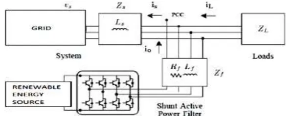
The proposed system consists of RES connected to the Dc link of a grid-interfacing inverter as shown in Figure 1.
IJEDR1804021
International Journal of Engineering Development and Research (
www.ijedr.org
)
113
Figure 2. Two-level four-leg PWM-VSI topologyThis converter topology is similar to the conventional three converter with the fourth leg connected to the neutral bus of the system. The fourth leg increases switching states from 8 (23) to 16 (24), improving control, flexibility and voltage quality, and is suitable for current unbalanced compensation. The voltage in any leg x of the converter, measured from the negative point of the -voltage (N), can be expressed in terms of switching states, as follows:
𝑉𝑥𝑛 = 𝑆𝑥− 𝑆𝑛𝑉𝑑𝑐 , 𝑥 = 𝑢, 𝑣, 𝑤, 𝑥 𝐸𝑞. 1
The mathematical model of the Active power filter derived from the equivalent circuit which is shown in fig. 2 is
𝑣0= 𝑣𝑥𝑛− 𝑅𝑒𝑞𝑖0− 𝐿𝑒𝑞
𝑑𝑖0
𝑑𝑡 𝐸𝑞. 2
where 𝑅𝑒𝑞 𝑎𝑛𝑑 𝐿𝑒𝑞 are the 4L-VSI output parameters, expressed as Thevenin impedances at the converter output terminals, 𝑍𝑒𝑞. Therefore, the Thevenin equivalent impedance is determined by a series connection of the ripple filter impedance 𝑍𝑓 and a parallel arrangement f between the system equivalent impedance 𝑍𝑠 and the load impedance 𝑍𝐿.
𝑍𝑒𝑞=
𝑍𝑠𝑍𝐿
𝑍𝑠+𝑍𝐿+𝑍𝑓 ≈ 𝑍𝑠+ 𝑍𝑓 𝐸𝑞. 3
for this model, it is assumed that ZL >> Zs , that is the resistive part of the system's equivalent impedance is neglected, and that the series resistance is in the range of 3-7% p.u., which is an acceptable approximation of the real system. Finally, in equation (2) 𝑅𝑒𝑞= 𝑅𝑓𝑎𝑛𝑑 𝐿𝑒𝑞= 𝐿𝑠+ 𝐿𝑓.
III. CURRENT REFERENCE GENERATION
IJEDR1804021
International Journal of Engineering Development and Research (
www.ijedr.org
)
114
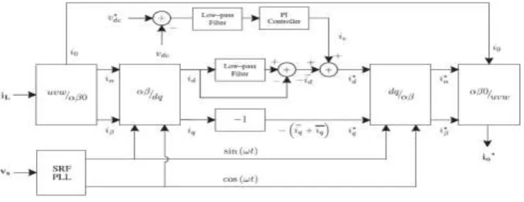
Fig 3. DQ-based Current Reference Generator Block DiagramThis module calculates the reference signal currents required by the converter to compensate reactive power, current harmonic and also current imbalance. The displacement power factor and the maximum total harmonic distortion of the load defines the relationships between the apparent power required by the active power filter, with respect to the load, as shown in below equation.
𝑆𝐴𝑃𝐹
𝑆𝐿 =
√𝑠𝑖𝑛𝜑(𝐿)+𝑇𝐻𝐷(𝐿)2
√1+𝑇𝐻𝐷(𝐿)2
Eq. 4
Where the value of 𝑇𝐻𝐷(𝐿) includes the maximum harmonic current, defined as double the sampling frequency fs. The frequency of the compensated maximum current harmonic component that is equal to two times the converter switching frequency.
The dq-based current reference generator scheme operated in a rotating reference frame[15]-[17]; therefore, the measured currents must be multiplied by the sin(wt) and cos(wt) signals. In a dq transformation, the d current component is synchronized with the corresponding phase-to-neutral system voltage and the q current components are phase-shifted by 90◦. From a Synchronous Reference Frame (SRF) PLL the sin(wt) and cos(wt)synchronized reference signals are obtained. The SRF-PLL generates the pure sinusoidalwaveform even when the system voltage is distorted.Tracking errors are eliminated, since SRF-PLLs are designed to avoid unbalancing in the phase voltage, harmonics (i.e. less than 5%th and 3%th in 5𝑡ℎ𝑎𝑛𝑑7𝑡ℎrespectively), and offset caused by the nonlinear load conditions and measurement errors.
𝑖𝑑 𝑖𝑞 = √ 2 3[ 𝑠𝑖𝑛𝑤𝑡 𝑐𝑜𝑠𝑤𝑡 −𝑐𝑜𝑠𝑤𝑡 𝑠𝑖𝑛𝑤𝑡] [
1 − 1
2 − 1 2
0 √3
2 − √
3 2 ] 𝑖𝐿𝑢 𝑖𝐿𝑣 𝑖𝐿𝑤 Eq. 5
A Low-Pass Filter (LFP) extracts the dc component of the phase-currents 𝑖𝑑 to generate the harmonic reference d component 𝑖𝑑. The reactive reference components of the d phase currents are obtained by phase-shifting the corresponding AC and dc components of 𝑖𝑞 by 180◦. In q order to keep the dc voltage constant, the amplitude of the converter reference current must be modified by adding an active power reference signal (𝑖𝑒) with the d-component. The resulting signals 𝑖𝑑∗ , and 𝑖𝑞∗ are transformed back into a three-phase system by applying the inverse Park and Clark transformation, The cutoff frequency of the LPF used in this paper is 20 Hz. The current that flows through the neutral of the load is compensated by injecting the same instantaneous value obtained from the phase-currents, phase-shifted by 180◦, as shown in below.
One of the major advantages of the dq-based current reference generator scheme is that allows the implementation of a linear controller in the dc-voltage control loop. However, one important disadvantage of the dq-based current reference frame algorithm used to generate the current reference is that a second order harmonic component is generated in 𝑖𝑑 and 𝑖𝑞 under unbalanced operating conditions. The amplitude of this harmonic depends on the percent of unbalanced load current (expressed as the relationship between the negative sequence current 𝑖𝐿,2 and the positive sequence current 𝑖𝐿,1 ). The second order harmonic cannot be removed from 𝑖𝑑 and 𝑖𝑞 , and therefore generates a 3rd harmonic in the reference current when it is converted back to abc frame. Figure shows the percent of system 6rd current imbalance and the percent of 3rd harmonic system current, in function of the percent of load current imbalance [18], [19]. Since the load current does not have a 3rd harmonic, the one generated by the active power filter flows to the power system. By the traditional Fuzzy controller the dc-voltage converter is controlled [20]. This is an important issue in the evaluation, since the cost function is designed using only current references, in order to avoid the use of weighting factors. Generally, these weighting factors are obtained by experimentally, and they are not well defined when different operating conditions are required. Additionally, the slow dynamic response of the voltage across the electrolytic capacitor does not affect the current transient response. For this reason, the Fuzzy controller represents a effective and simple alternative for the dc-voltage control.
IJEDR1804021
International Journal of Engineering Development and Research (
www.ijedr.org
)
115
Figure 4. Basic representation of FLC
The determination of the output control signal, is done with an inference engine with a rule base having if-then rules in the form of
"IF ε is ... AND Δε is ..., THEN output is ..."
With the help of rule base, the value of the output is changed according to the value of the error signal ε, and the rate-of-error Δε. The structure determination of the rule base is using trial-and-error methods and also done through experimentation.
All the variable' of fuzzy subsets for the inputs ε and Δε are defined as (NB, NM, NS, Z, PS, PM, PB). The fuzzy control rule base is illustrated in the Table I.
Table.1 FLC Rule Base
𝜀 ∆𝜀
NB NM NS ZE PS PM PB
NB NB NB NB NB NM NS ZE
NM NB NB NM NM NS ZE PS
NS NB NM NS NS ZE PS PM
ZE NB NM NS ZE PS PM PM
PS NM NS ZE PS PS PM PB
PM NS ZE PS PM PM PB PB
PB ZE PS PM PB PB PB PB
V. SIMULATED RESULTS
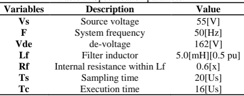
A simulation model for the three-phase four-leg PWM converter with the parameters shown in Table 2 which has been developed using MATLAB-Simulink. The main objective of this is to verify the current harmonic compensation effectiveness of the proposed control scheme under different operating conditions. A non-linear load was used as a six pulse rectifier.
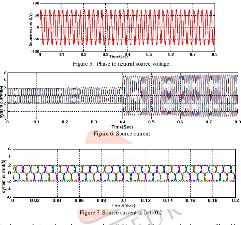
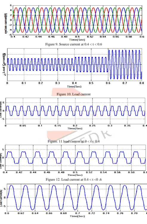
In the simulated results shown in Figures 8-15, the active power filter starts to compensate at t =0.2. At this time, the active power filter injects an output current 𝑖𝑜𝑢 to compensate current harmonic components, current unbalanced, and neutral current simultaneously. During compensation, the system currents show sinusoidal waveform, with low total harmonic distortion. At t =0.4, a three-phase balanced load step change is generated from 0.6 to 1.0 p.u.
Table 2. Specification parameter
Variables Description Value
Vs Source voltage 55[V]
F System frequency 50[Hz]
Vde de-voltage 162[V]
Lf Filter inductor 5.0[mH][0.5 pu]
Rf Internal resistance within Lf 0.6[x]
Ts Sampling time 20[Us]
Tc Execution time 16[Us]
IJEDR1804021
International Journal of Engineering Development and Research (
www.ijedr.org
)
116
Figure 5. Phase to neutral source voltage
Figure 6. Source current
Figure 7. Source current at 0<t<0.2
Simulated results have shown the compensation effectiveness of the proposed active power filter. Above
figures show that the proposed control scheme effectively eliminates unbalanced currents. The
dc-voltage remains stable throughout the active power filter operation.
IJEDR1804021
International Journal of Engineering Development and Research (
www.ijedr.org
)
117
Figure 9. Source current at 0.4 < t < 0.6
Figure 10. Load current
Figure. 11 load current at 0 < t < 0.4
IJEDR1804021
International Journal of Engineering Development and Research (
www.ijedr.org
)
118
Figure 13.Load current at 0.6< t< 0.8
Conclusion
Improved current harmonics and a reactive power compensation scheme for power distribution systems with generation from renewable sources has been proposedto improve the currentquality of the distribution system. Advantages of this proposed scheme is related to its simplicity, modeling and implementation. The MATLAB/SIMULINK simulation model of the proposed system with the connection of renewable energy sources is shown and also validated. The use of a dq-based current reference generation scheme for the converter current loop proved to be an effective solution for active power filter applications, improving capability of current tracking, and transient response. Simulated results have shown that the proposed control method is a good alternative to classical linear control methods. simulated results have shown the compensation effectiveness of the proposed active power filter.
REFERENCES
[1]. J. Rocabert, A. Luna, F. Blaabjerg, and P. Rodriguez,[2012]. “Control of power converters in ac microgrids,”Power Electronics, IEEE Transactions on, Vol. 27, No. 11, pp. 4734–4749,
[2]. M. Aredes, J. Hafner, and K. Heumann, [1997]. “Three phase four-wire shunt active filter control strategies,” Power Electronics, IEEE Transactions on, Vol. 12, No. 2, pp. 311–318.
[3]. S. Naidu and D. Fernandes, [2009].“Dynamic voltage restorer based on a four leg voltage source converter,” Gener. Transm. Distrib, IET, Vol. 3, No. 5, pp. 437–447.
[4]. N. Prabhakar and M. Mishra, [2010]. “Dynamic hysteresis current control to minimize switching for threephase four-leg vsi topology to compensate nonlinear load,” Power Electronics, IEEE Transactions on, Vol. 25, No. 8, pp. 1935–1942.
[5]. V. Khadkikar, A. Chandra, and B. Singh, [2011]. “Digital signal processor implementation and performance evaluation of split capacitor, four leg and three h-bridge based three-phase four-wire shunt active filters,” Power Electronics, IET, Vol. 4, No. 4, pp. 463–470.
[6]. F. Wang, J. Duarte, and M. Hendrix, [2011]. “Grid interfacing converter systems with enhanced voltage quality for microgrid application; concept and implementation,” Power Electronics, IEEE Transactions on, Vol. 26, No. 12, pp. 3501–3513. [7]. X. Wei, [201]. “Study on digital pi control of current loop in active power filter,” Electrical and Control Engineering(ICECE), 2010 International Conference on, pp. 4287–4290.
[8]. R. de Araujo Ribeiro, C. de Azevedo, and R. de Sousa, [2012]. “A robust adaptive control strategy of active power f i l t e r s f o r p o w e r- f a c t o r c o r r e c t i o n, h a rmo n i c compensation, and balancing of nonlinear loads,” Power Electronics, IEEE Transactions on, Vol. 27, No. 2, pp. 718–730.
[9]. J. Rodriguez, J. Pontt, C. Silva, P. Correa, P. Lezana, P. Cortes, and U. Ammann, [2007]. “Predictive current control of a voltage source inverter,” Trans. Ind. Electron., IEEE, Vol. 54, No. 1, pp. 495–503.
[10]. P. Cortes, G. Ortiz, J. Yuz, J. Rodriguez, S. Vazquez, and L. Franquelo, [2009]. “Model predictive control of an inverter with output LC filter for UPS applications,” Trans. Ind. Electron., IEEE, Vol. 56, No. 6, pp. 1875–1883.
[11]. R. Vargas, P. Cortes, U. Ammann, J. Rodriguez, and J. Pontt, [2007]. “Predictive control of a three-phase neutral point- clamped inverter,” Trans. Ind. Electron., IEEE, Vol. 54, No. 5, pp. 2697–2705.
[12]. P. Cortes, A. Wilson, S. Kouro, J. Rodriguez, and H. Abu-Rub, [2010]. “Model predictive control of multilevel cascaded H-bridge inverters,” Trans. Ind. Electron., IEEE, Vol. 57, No. 8, pp. 2691–2699.
[13] P. Lezana, R. Aguilera, and D. Quevedo, [2009].“Model predictive control of an asymmetric flying capacitor converter,” Trans. Ind. Electron., IEEE, Vol. 56, No. 6, pp. 1839–1846.
[14]. P. Correa, J. Rodriguez, I. Lizama, and D. Andler,[2009]. “A predictive control scheme for current-source rectifiers,” Trans. Ind. Electron., IEEE, Vol. 56, No. 5, pp.1813–1815.
[15]. M. Rivera, J. Rodriguez, B. Wu, J. Espinoza, and C. Roj as, [2012]. “Current control for an indirect matrix converter with filter resonance mitigation,” Trans. Ind. Electron., IEEE, Vol. 59, No. 1, pp. 71–79.
[16]. P. Correa, M. Pacas, and J. Rodriguez, [2007].“Predictive torque control for inverter-fed induction machines,” Trans. Ind. Electron., IEEE, Vol. 54, No. 2, pp.1073–1079.
[17]. M. Odavic, V. Biagini, P. Zanchetta, M. Sumner, and M. Degano, [2011]. “One sample-period-ahead predictive current control for high-performance active shunt power filters,” Power Electronics, IET, Vol. 4, No. 4, pp. 414–423.
[18]. R. de Araujo Ribeiro, C. de Azevedo, and R. de Sousa, [2012]. “A robust adaptive control strategy of active power filters for power-factor correction, harmonic compensation, and balancing of nonlinear loads,” Power Electronics, IEEE Transactions on, Vol. 27, No. 2, pp.718–730.
[19]. M. Sumner, B. Palethorpe, D. Thomas, P. Zanchetta, and M. Di Piazza, [2002]. “A technique for power supply harmonic impedance estimation using a controlled voltage disturbance,” Power Electronics, IEEE Transactionson, Vol. 17, No. 2, pp. 207–215.
[20]. D. Driankov, H. Hellendoom and M. Reinfrank [1993]. “An Introduction to Fuzzy Control,” Springer-Verlag.
[21]. Karuppanan P., Mahapatra K.K., [2011]. “PLL with fuzzy logic controller based shunt active power filter for harmonic and reactive power compensation” IEEE Conference, IICPT, Power Electronics, pp.1-6.