International Journal Of Engineering Research And Development
e- ISSN: 2278-067X, p-ISSN: 2278-800X, www.ijerd.com
Volume 14, Issue 5 (May Ver. II 2018), PP.27-32
Harmonics Analysis Of A Single Phase Inverter Using Matlab
Simulink
Oladipo Folorunsoand Temitope Ayeni
Department of Electrical/Electronics Engineering, AfeBabalola University, PMB 5454, Ado Ekiti, Nigeria Corresponding Author: Oladipo Folorunso, email: [email protected]
ABSTRACT: This paper focus on modelling and simulation of single phase inverter. An inverter is a circuit that converts DC sources to AC sources. The model is implemented using MATLAB/Simulink software with the SimPower System Block Set based on computer simulation. In order to find the harmonics content and total harmonic distortion (THD), Fast Fourier Transform (FFT) analysis is used using MATLAB Simulink software. It is shown that the performance of the inverter circuit with the harmonics filtering circuit having a THD value of 28.79% is better than the inverter circuit without the harmonics filtering circuit having a THD value of 87.53%.
KEYWORDS:SimPower, THD, FFT, inverter.
--- --- Date of Submission: 05-05-2018 Date of acceptance: 21-05-2018 ---
---I INTRODUCTION
An inverter is an electronic circuitry that converts direct current (DC) power into an alternating current (AC) power. DC flows in one direction, it’s such that current leaves the power source from the positive terminal and flows through the circuit and then terminates at the negative terminal of the power source(Osuwaet al., 2014). The major problem of inverter is the harmonics produced in the system during operation.
Power quality is very important to commercial and industrial power system designs. Ideally, the electrical supply should be a perfect sinusoidal waveform without any kind of distortion. If the current or voltage waveforms are distorted from its ideal form it will be termed as harmonic distortion. This harmonic distortion could result because of many reasons (Radhakrishnaet al., 2016). Harmonics are caused by non-linear load, these are load that draws a non-sinusoidal current from a sinusoidal voltage source (Manish et al., 2014).
Folorunso et al., 2015, stated that harmonic contributes to the economic disadvantages of electric devices. When these devices are constantly subjected to harmonic signals, there is possibility of damaging the circuit component which can cause electrical hazard. An inverter is one of such. Inverter has caused a lot of damages to domestic and industrial devices due to harmonic effect. That is, due to the application of non-linear loads on the power system harmonics is produced and due to the presence of harmonics, it can lead to an increase in current, unwanted heating and power losses. This can cause harm to electrical devises connected to the power system.
II LITERATURES 2.1 Inverter
An inverter is a device that converts the DC sources to AC sources. The purpose of a DC/AC power inverter is typically to take DC power supplied by a battery, such as a 12-volt car battery, and transform it into a 240-volt AC power source operating at 50 Hz, emulating the power available at an ordinary household electrical outlet.
2.2 Classification of Inverters.
Inverters differ in their outputs, providing varying levels of efficiency and distortion that can affect electronic devices in different ways. They can be classified as square wave inverter, modified square wave inverter and pure sine wave inverter
2.2.1 Square Wave Inverter:
2.2.2 Modified Sine Wave Inverter
The output of a modified sine wave inverter is similar to a square wave output except that the output goes to zero volts for a time before switching positive or negative (Sisir Mazumder, 2015).
Modified sine wave is more like the square wave which has less harmonic distortion compared to square wave. The harsh corners from the square wave were eliminated to transform it to a modified sine wave. Although it is less harmful to devises compared to the square wave, it still heats up the coil in filter due to large amount of harmonic distortion and dissipates power (Paul, 2010).
2.2.3 Pure Sine Wave
A pure sine wave inverter produces a nearly perfect sine wave output (<3% total harmonic distortion) that is essentially the same as utility-supplied grid power. Thus it is compatible with all AC electronic devices. Its design is more complex, and costs more per unit power (Sisir Mazumder, 2015).Unlike square wave and modified sine wave, pure sine wave inverters maintain the best quality due to the least number of harmonic distortions present in it. Usually sine wave inverter are more expensive but it allows to us use all AC appliances and reduces the humming noise of inductive loads (Paul, 2010)
2.3 Harmonics
Harmonics has been more of an issue nowadays due to the increased usage of nonlinear loads which are the cause of harmonics. The non-linear loads here refer to loads which current is not proportional to the applied voltage. It must be noted that different non-linear loads will have different slight voltage current characteristics. Sometimes a slight increase in voltage can cause the current to double.
Any periodic, distorted waveform can be expressed as a sum of pure sine waves in which the frequency of each sinusoid is an integer multiple of the fundamental frequency.
𝑓 𝑡 = 𝑎0+ ∞𝑛=1(𝑎𝑛cos 𝑛𝜔𝑡 + 𝑏𝑛sin(𝑛𝜔𝑡)) (2.1)
Where 𝑎0= 1
𝑇 𝑓(𝑡)𝑑𝑡 𝑇
0 (2.2)
𝑎𝑛 = 2
𝑇 𝑓 𝑡 cos 𝑛𝜔𝑡 𝑑𝑡 𝑇
0 (2.3)
𝑏𝑛= 2
𝑇 𝑓 𝑡 sin 𝑛𝜔𝑡 𝑑𝑡 𝑇
0 (2.4)
Harmonics are caused by non-linear loads that is loads that draw a non- sinusoidal current from a sinusoidal voltage source.
Some examples of harmonic producing loads are: Electric arc furnaces, static VAR compensators, inverters, DC converters, switch-mode power supplies, AC or DC motor drives.
2.4 Voltage and Current Distortion
Nonlinear loads are the sources of harmonic current causing distorted current waveforms. Voltage distortion is the result of distorted currents passing through the linear, series impedance of the power delivery system. Therefore, it is always the current distortion that results in voltage distortion.
2.5 Total Harmonic Distortion
The total harmonic distortion is a measurement of the harmonic distortion present and is defined as the ratio of the sum of the powers of all harmonic components to the power of the fundamental frequency. THD was used to characterize the linearity of audio systems and the power quality of electric power systems. In power systems, lower THD means reduction in peak currents, heating, emissions, and core loss in motors.
2.5.1 Voltage Total Harmonic Distortion
Voltage distortion consists of very sharp notches and spikes in voltage. When applied to the equivalent circuit, that high frequency voltage does not cause much change in the inductive magnetizing current, but causes a change in the load current.
2.5.2 Current Total Harmonic Distortion
Current total harmonic distortion is caused by the motor itself due to non-linearity of the magnetizing current. The current total harmonic distortion will be higher when the motor is unloaded.
2.6 Total Harmonic Distortion Analysis
2.7 Even Harmonics
Even harmonics (2nd, 4th, and 6th) are less likely to occur at levels detrimental to electrical systems. This is because non-linear loads normally generate odd harmonics rather than even harmonics. Furthermore, when both the positive and negative half cycles of a waveform are similar in shape, the Fourier series contain only odd harmonics.
2.8 Odd Harmonics
Odd harmonics (3rd, 5th, and 7th) are more common in power systems and are the ones which lead to severe consequences if they are not controlled. Each odd harmonic is associated with one of the sequence component (positive, negative or zero). The phase sequence is very important because it determines the effect of the harmonic on the operation of the electrical equipment.
1.9 Pulse Width Modulation
Pulse width modulation (PWM) is a powerful technique for controlling analogue with a processor’s digital outputs. It is also known as pulse duration modulation (PDM). The leading edge of the carrier pulse remains fixed and the occurrence of the trailing of the pulses varies. PWM signals find a wide application in modern electronics. Some of these reasons are: We can obtain the output voltage control foregoing any other additional element, lower order harmonic can be eliminated or compact beside its output voltage control with this method and as we know higher order harmonics can be filtered easily, easy to Generate – PWM signals are quite easy to generate. Many modern microcontrollers include PWM hardware within the chip; using this hardware often takes very little attention from the microprocessor and it can run in the background without interfering with executing code.
Pulse Width Modulation (PWM) Techniques have been popular in the area of power electronics and drive systems. PWM is commonly used in applications like motor speed control, converters audio amplifiers etc. PWM is used to adjust voltage applied to the motor. There is no single PWM method which can suite for all applications. As per the advanced technology in solid state power electronic devices and microprocessors, various pulse-width modulation (PWM) techniques have been developed for different industrial applications. The main objective of the PWM is to control the inverter output voltage and to reduce the harmonic content in the output voltage. The pulse width modulation (PWM) techniques are mainly used for voltage control. These techniques are most efficient and they control the drives of the switching devices. The different PWM techniques are: Sinusoidal Pulse Width Modulation (SPWM) and Third Harmonic Injection Pulse Width Modulation (THIPWM)
2.9.1 Sinusoidal Pulse Width Modulation
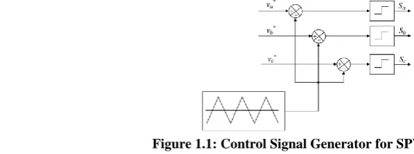
The sinusoidal pulse-width modulation (SPWM) technique produces a sinusoidal waveform by filtering an output pulse waveform with varying width. As shown in Figure 1, a low frequency sinusoidal modulating waveform is compared with a high-frequency triangular waveform, which is called the carrier waveform. The switching state is changed when the sine waveform intersects the triangular waveform. The crossing positions determine the variable switching times between states. In three-phase SPWM, a triangular voltage waveform (Vt) is compared with three sinusoidal control voltages (Va, Vb, and Vc), which are 120 out of phase with each other and the relative levels of the waveforms are used to control the switching of the devices in each phase leg of the inverter
Figure 1.1: Control Signal Generator for SPWM 2.9.2 Third Harmonic Injection Pulse Width Modulation
possible to obtain a significant amplitude increase at the output voltage without loss of quality, as represented in Figure 2.
Figure 2.2: Third Harmonic Injections to the Reference Signal
III METHODOLOGY
In this work, MATLAB-simulation software is used to analyze the effect of harmonics on a single phase inverter. This section deals with the simulation results of the circuit with and without a harmonics filtering circuit. In practice, pure sine wave output from inverter is preferred, but is difficult to obtain a pure sine wave. In order to obtain a pure sine wave, a filter circuit is created across the output of the inverter. With the help of the filter, it is possible to remove the harmonics in the output of the inverter. A low pass filter is used in the simulation circuit.
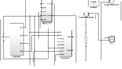
Figure 3.1 is the Simulink design view of the inverter without filter. This inverter output would surely has harmonics due to the magnetic devices used in the construction. But to reduce this harmonics, it is possible to employ filter as shown in Figure 3.2
The filter is simply a combination of inductor and capacitor in series. The capacitor, inductor low pass filter has the advantage of passing signals with low frequency but cannot easily pass high frequency signal component because, the impedance of the inductor rises when the frequency is high.
Figure 3.1: Simulink Design view of the inverter without filter.
Figure 3.2: Simulink Design view of the inverter with filter
IV RESULTS
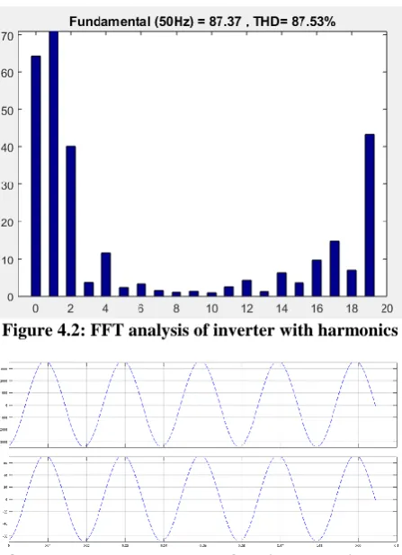
Figure 4.1: Output voltage and current waveform with harmonics
Figure 4.2: FFT analysis of inverter with harmonics
Figure 4.3: Output voltage and current of the inverter without harmonics.
Figure 4.4: FFT analysis of inverter without harmonics
V CONCLUSION
shown that the performance of the inverter circuit with the harmonics filtering circuit having a THD value of 28.79% is better than the inverter circuit without the harmonics filtering circuit having a THD value of 87.53%.
REFERENCES
[1]. Folorunso O, Ojo A.O, Ajibade A., (2015). Harmonicanalysis and it mathematical philosophy.
[2]. International Journal of Science and Engineering Investigation. Vol4., issue 44, ISSN: 2251-8843
[3]. Kulkarni, W. S. (2003). Harmonic Analysis of three phase PWM inverter systems using MATLAB. American Society for
Engineering Education Annual Conference & Exposition.
[4]. Mburu, M. B. (2009). A Pure Sine Wave Inverter for House Backup.
[5]. Paul, P. (2010). Performance and Analysis of DC-AC Pure Sine Wave Inverter.
[6]. Radhakrishna Das, J. K. (2016). Harmonic Analysis of Single Phase Inverter . International Journal of Advanced Research in
Electrical, Electronics and Instrumentation Engineering , 1, 6.
[7]. Sisir Mazumder, S. D. (2015). Design of Inverters with Harmonics Reduction Technique Using Artificial Neural Network.
International Journal of Innovative Science, Engineering & Technology, 1-3.