© 2015 IJSRSET | Volume 1 | Issue 4 | Print ISSN : 2395-1990 | Online ISSN : 2394-4099 Themed Section: Engineering
Limitations of a ZN-PI Controller for Liquid Level Control of
Horizontal Cylindrical Tank
S. Mourouga Pragash1, R. Ananda Natarajan2
1Associate Professor, Department of Electronics and Instrumentation Engineering, Pondicherry Engineering College, Pondicherry, India
2Professor, Department of Electronics and Instrumentation Engineering, Pondicherry Engineering College, Pondicherry, India
ABSTRACT
Most chemical processes are inherently nonlinear. However, because of their simplicity, linear control algorithms have been used for the control of nonlinear processes. In this work, horizontally placed cylindrical tanks whose parameters vary with respect to process variable are considered for study. [ Anandanatarajan, R.,Chidambaram,M., and Jayasingh, T., Limitations of PI controller for a first- order nonlinear process with dead time. ISA transactions 45, 185-199(2006)]. The time constant and gain of the chosen process vary as a function of level. The limitations of the conventional PI controller tuned using Ziegler Nichols (ZN) settings for the chosen process are carried out. The servo and regulatory responses for various magnitudes of set point changes and load changes at various operating points with the controller tuned only at a chosen nominal operating point are obtained. Simulation is conducted within MATLAB environment to verify the performances of the system in terms of Settling Time, Overshoot (OS) and Simulation is conducted within MATLAB environment to verify the performances of the system in terms of Settling Time and Overshoot (OS) Keywords : Horizontal Cylindrical Tank, ZN-PI Controller, Liquid Level Control, Nonlinear Process
I.
INTRODUCTIONIndustries such as petro-chemical industries, paper making industries, waste management and others are the vital industries where liquid level and flow control are essential. Liquids will be processed by chemical or mixing treatment in the tanks, but always the level fluid in the tanks must be controlled, failing to do so may lead to serious shutdown process. So it is necessary to maintain the level of tank at particular set point.
Most of the industries deal with nonlinear process tanks such as conical, spherical, hemispherical
horizontal cylindrical tanks. But the majority of the findings in control theory deal only with the linear system designs. So the control of nonlinear shape of process tank presents a challenging task mainly due to its non-linearity and constantly changing cross section. Hence, horizontal cylindrical tank level process is taken up for present study.
II.
HORIZONTAL CYLINDRICAL TANK LEVEL PROCESS AND ITS MATHEMATICAL MODELvariations in the flow rate from one process to another process. The level can vary substantially from the set point, as long as the vessel does not overflow or go dry. Surge vessels are used to help reduce the effect of flow rate variations between interconnected process units.
Fin
Fout L
D
R h
D
R-h
R
Fig.1 : Structure of horizontal cylindrical Tank level process
The mathematical model of the horizontal cylindrical tank liquid level system considered for the study is expressed as,
Let R, be radius of cross section.
h, be level of liquid inside the tank.
D, be diameter of cross section.
L, be length of the tank.
Fig. 2: cross section of horizontal cylindrical tank
Base area between 0 to R : (If the level of the tank is below centre of the circle)
Let R be the radius of the circle, a be the chord length, s be the arc length, h be the height of the arced portion, and r be the height of the triangular portion. Then the radius is
R
=
r
+
h
The area A of the (shaded) segment in fig.2(a) is then simply given by the area of the circular sector (the entire wedge-shaped portion) minus the area of the triangular portion,
A area = area of circular sector – area of triangular portion.
−
−
= − R sin2
2 1 R
h R cos 2 R 2
1 2 1 2
−
−
= − R 2sin cos
2 1 R
h R cos
R2 1 2
− −
− −
−
= −
R h R R
) h R ( R R R
h R cos R
2 2
2 1
2
2 1
(
R h)
2Rh h2R h R cos
R − − −
−
the volume V of the cylindrical segment is given by multiplying the area of a circular segment of height h by the length of the tank L,
(
)
− − − −= 2 −1 R h 2Rh h2
R h R cos R L
V (2)
Base area between R to 2R: (If the level of the tank is above centre of the circle)
A
(
)
− − − − = − R R h cos h Rh 2 R h 2
R2 2 1
−
−
−
=
−R
h
R
cos
r
2 1(
)
− + − − − − = − R h R cos R r h Rh 2 h Rr2 2 2 2 1
(
)
21 2
2
cos R h Rh h
R h R R
A − − −
− = − (3)
the volume V of the cylindrical segment is given by multiplying the area of a circular segment of height by the length of the tank ,
(
)
21 2 h Rh 2 h R R h R cos LR
V − − −
− = − (4)
Both the equations (2) and (4) for the level from 0 to R and level R to 2R respectively are identical
Note that the above equation gives When h = 0
0
=
V
When h=R2
2L
R
V
=
When h=2R
L R
V =
2 as expected.Therefore the equation holds good for all the different level of the tank. Differentiating with respect to h will get, ( )
(
)
( ) ( ) − − + − − − − − − − − = − 1 h Rh 2 h R 2 h Rh 2 2 1 h R R 1 R h R 1 1 R L dhdV 2 2
1 2 2 2 ( )
(
)
( ) − + − − − − − − = − 2 2 1 2 2 2 2 h Rh 2 h R 2 h Rh 2 2 1 h R R ) h R ( R R L(
)
−
−
−
−
−
−
=
2 2 2 2 2h
Rh
2
h
Rh
2
h
R
h
Rh
2
R
L
(
)
−
−
−
−
+
−
−
=
2 2 2 2 2 2h
Rh
2
h
Rh
2
Rh
2
h
R
h
Rh
2
R
L
−
−
+
−
−
=
2 2 2 2 2h
Rh
2
Rh
4
h
2
R
h
Rh
2
R
L
−
−
+
−
−
=
2 2 22
2
Rh
h
Rh
4
h
2
R
h
Rh
2
L
2 2 h Rh 2 ) h Rh 2 ( L 2 − − = 2h
Rh
2
L
2
−
=
dV
=
2
L
2
Rh
−
h
2dh
(5)Consider the horizontal cylindrical tank level process, as per the conservation of mass, we have
Fin Fout
dt
dV = −
(6)
Fin - is Volume flow rate at inlet Fout - is Volume flow rate at outlet in conservation of mass,
2 Fin Fout
dt dh h Rh L
2 − = −
(7)
2 out in
h
Rh
2
L
2
F
F
dt
dh
−
−
=
(8)
Where Fout=
c
h
, c is valve coefficient. A delay time (Td) is introduced in the inflow Fin to incorporate a dead time in the process and u is a linear function. The equation becomes
2
2
2
)
(
h
Rh
L
h
c
T
t
u
dt
dh
d−
−
−
=
(9) (4)
This is the mathematical model of the horizontal cylindrical tank level process.
III.
TUNING OF PI CONTROLLERThe goal of PI controller tuning is to determine parameters that meet closed loop system performance specifications, and to ensure the robust performance of the control loop over a wide range of operating conditions. Practically, it is often difficult to simultaneously achieve all of these desirable qualities. For example, if the PI controller is adjusted to provide better transient response to set point change, it usually results in a sluggish response when under disturbance conditions. On the other hand, if the control system is made robust to disturbance by choosing conservative values for the PI controller, it may result in a slow closed loop response to a set point change. A number of tuning techniques that take into consideration the nature of the dynamics present within a process control loop have been proposed (Ziegler and Nichols, 1942; Cohen and Coon, 1953; Åström and Hägglund, 1984; and Atherton, 1993).[1-3] All these methods are based upon the dynamical behavior of the system under either open-loop or closed-loop conditions
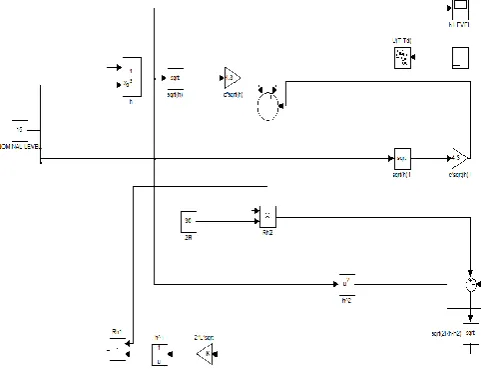
The Simulink model of horizontal cylindrical tank level process is shown in figure 3.. The height, end radius and length of the tank are 30 cm, 15 cm and 30cm respectively. A dead time (Td) of 30 seconds is introduced in the process through software. The time constant and the gain of the process increase as the level increases.. To obtain the transfer function model, reaction curves for various magnitudes of input at 50% nominal operating point are obtained by MATLAB Simulink software as shown in the figure 4. Different step changes in input (say) 10%, 20 %, 30% and 40% given to the process to obtain reaction curves. The corresponding process gain and time constant are tabulated in the Table 1.
Fig. 3 Simulink model of horizontal cylindrical tank level process
Fig 4. Reaction curve for different set values
0 1000 2000 3000 4000 5000 6000 7000 8000 9000 10000 20
30 40 50 60 70 80 90 100
Time in sec
L
e
ve
l
in
pe
r
c
e
nt
a
ge
(
%
)
Table 1. Model parameters obtained from simulated reaction curves for horizontal cylindrical tank
Step change
Process gain
Time
constant Time delay
40% 2.125 3745 39
30% 2.04 3724 24.9
20% 1.963 3615 12.9
10% 1.88 3457 9.3
-10% 1.72 3015 17
-20% 1.64 2767 42.5
-30% 1.55 2547 59
-40% 1.477 2313 81
For the simulation study, the reaction curve for +10% change at 50% nominal operating point is considered to tune the PI controller. The tuning parameters obtained are Kc=1.4407 and Ki=0.0023
IV.
PERFORMANCE OF PI CONTROLLER FOR THEHORIZONTAL CYLINDRICAL TANK LEVEL
PROCESS
The servo response on the Horizontal cylindrical tank level process for increase in set points, and decrease in set point at different time interval but all of them tuned at the nominal operating point of 50% shown in Figure 5 & 6. Figure 7& 8 shows the regulatory response for 10% increasing load change and 10% decreasing load change from its nominal operating point. The performance of ZN PI controller is oscillatory response and produce high ISE and IAE values given in the table.2.
Figure.5 Servo Response of hemispherical tank level process for 20% increase in set point from nominal
operating point of 50% using ZNPI controller
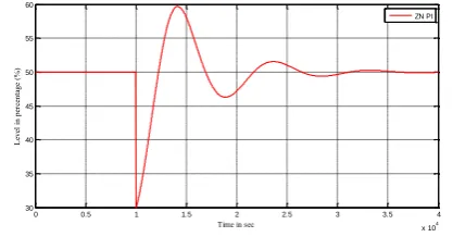
Figure.6 Servo Response of hemispherical tank level process for 20% decrease in set point from nominal
operating point of 50% using ZNPI controller
Figure.7 Regulatory response of hemispherical tank level process for increase in 20% load at t=10000 sec at
50% nominal operating point using ZNPI controller
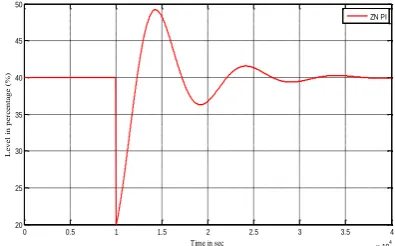
Figure.8 Regulatory response of hemispherical tank level process for decrease in 20% load at t=10000 sec
at 50% nominal operating point using ZNPI controller
0 0.5 1 1.5 2 2.5 3
x 104 50
55 60 65 70 75 80 85 90
Time in sec
L
eve
l
in
pe
rc
ent
age
(
%
)
ZN PI
0.5 1 1.5 2 2.5 3
x 104 20
25 30 35 40 45 50 55
Time in sec
L
eve
l
in
pe
rc
ent
age
(
%
)
ZN PI
0 0.5 1 1.5 2 2.5 3 3.5 4
x 104 40
45 50 55 60 65 70
Time in sec
L
eve
l
in
pe
rc
ent
age
(
%
)
ZN PI
0 0.5 1 1.5 2 2.5 3 3.5 4
x 104
30 35 40 45 50 55 60
Time in sec
L
eve
l
in
pe
rc
ent
age
(
%
)
V.
ANALYSIS OF ROBUSTNESS OF ZN PI CONTROLLER FOR HORIZONTAL CYLINDRICALTANK LEVEL PROCESS
The change in nominal operating point from 50% to 60% for increase in set points, and decrease in set point at different time interval but all of them tuned at the nominal operating point of 50% horizontal cylindrical tank level process are shown in figure 9to 10. Figure 11 & 12 show the regulatory response for increase in 10% and decrease in 10% load from its 60% of nominal operating point. The PI controller gives large undershoot for negative load and takes large time to reaches steady state value and lower overshoot for positive load changes for set point changes controller exhibits overshoot for increasing set point. The performance index of the controller is given in the table 3. Similarly Figure 13 to 16 shows the servo and regulatory response of Horizontal cylindrical tank level process for changing nominal operating point from 50% to 40%. Table 4 represents the performance index of the PI controller for change in nominal operating point from 50% to 40%.
Figure.9 Servo Response of Horizontal cylindrical tank level process for 10% increase in set point from nominal operating point of 60% using ZNPI controller
but tuned at 50% of nominal operating point
Figure.10 Servo Response of Horizontal cylindrical tank level process for 10% decrease in set point from nominal operating point of 60% using ZNPI controller
but tuned at 50% of nominal operating point
0 5000 10000 15000 20000 25000 30000 35000 40000
60 62 64 66 68 70 72 74
Time in sec
L
eve
l
in
pe
rc
ent
age
(
%
)
ZN PI
5,000 10000 15000 20000 25000 30000 35000 40000
45 50 55 60 65
Time in sec
L
eve
l
in
pe
rc
ent
age
(
%
)
ZN PI
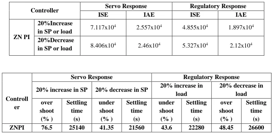
Table .2 Performance index for Horizontal cylindrical Tank at nominal operating point of 50%
Controller Servo Response Regulatory Response
ISE IAE ISE IAE
ZN PI
20%Increase
in SP or load 7.117x10
4 2.557x10⁴ 4.855x10⁴ 1.897x10⁴ 20%Decrease
in SP or load 8.406x10⁴ 2.46x10⁴ 5.327x10⁴ 2.12x10⁴
Controll er
Servo Response Regulatory Response
20% increase in SP 20% decrease in SP 20% increase in load
20% decrease in load over
shoot (% )
Settling time
(s)
under shoot (% )
Settling time
(s)
under shoot (% )
Settling time
(s)
over shoot
(% )
Settling time
(s)
Figure.11 Regulatory response of hemispherical tank level process for increase in 20% load at t=10000 sec at 60% nominal operating point using ZNPI controller
but tuned at 50% of nominal operating point
Figure.12 Regulatory response of hemispherical tank level process for decrease in 20% load at t=10000 sec
at 60% nominal operating point using ZNPI controller but tuned at 50% of nominal operating
point
Figure.13 Servo Response of Horizontal cylindrical tank level process for 10% increase in set point from nominal operating point of 40% using ZNPI controller
but tuned at 50% of nominal operating point
Figure.14 Servo Response of Horizontal cylindrical tank level process for 10% decrease in set point from nominal operating point of 40% using ZNPI controller
but tuned at 50% of nominal operating point
Figure.15 Regulatory response of hemispherical tank level process for increase in 20% load at t=10000 sec at 40% nominal operating point using ZNPI controller
but tuned at 50% of nominal operating point
Figure. 16 Regulatory response of hemispherical tank level process for decrease in 20% load at t=10000 sec
at 40% nominal operating point using ZNPI controller but tuned at 50% of nominal operating
point.
0 0.5 1 1.5 2 2.5 3 3.5 4
x 104 50
55 60 65 70 75 80
Time in sec
L
eve
l
in
pe
rc
ent
age
(
%
)
ZN PI
0 0.5 1 1.5 2 2.5 3 3.5 4
x 104
40 45 50 55 60 65 70 75
Time in sec
L
eve
l
in
pe
rc
ent
age
(
%
)
ZN PI
0 0.5 1 1.5 2 2.5 3
x 104 40
42 44 46 48 50 52 54 56 58 60
Time in sec
L
e
ve
l
in
pe
rc
e
nt
a
ge
(
%
)
ZN PI
0.5 1 1.5 2 2.5 3
x 104 24
26 28 30 32 34 36 38 40 42
Time in sec
L
eve
l
in
pe
rc
ent
age
(
%
)
ZN PI
0 0.5 1 1.5 2 2.5 3 3.5 4
x 104 30
35 40 45 50 55 60
Time in sec
L
eve
l
in
pe
rc
ent
age
(
%
)
ZN PI
0 0.5 1 1.5 2 2.5 3 3.5 4
x 104 20
25 30 35 40 45 50
Time in sec
L
eve
l
in
pe
rc
ent
age
(
%
)
Table 3 Performance index for Horizontal cylindrical Tank at nominal operating point of 60%
Controller Servo Response Regulatory Response
ISE IAE ISE IAE
ZN PI
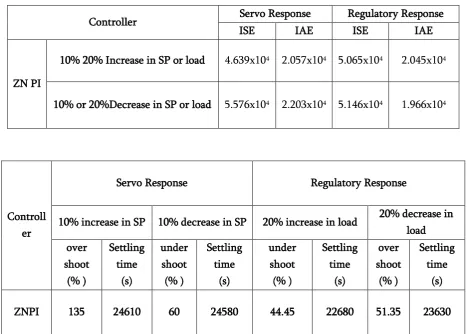
10% 20% Increase in SP or load 4.639x10⁴ 2.057x10⁴ 5.065x10⁴ 2.045x10⁴
10% or 20%Decrease in SP or load 5.576x10⁴ 2.203x10⁴ 5.146x10⁴ 1.966x10⁴
Table 4. Performance index for Horizontal cylindrical Tank at nominal operating point of 40%
Controller
Servo Response Regulatory Response
ISE IAE ISE IAE
ZN PI
10% or 20% Increase in SP or load 2.516x10⁴ 1.591x10⁴ 4.3889x10⁴ 1.63x10⁴
10% or 20% Decrease in SP or load 3.181x10⁴ 1.537x10⁴ 5.265x10⁴ 2.146x10⁴ Controll
er
Servo Response Regulatory Response
10% increase in SP 10% decrease in SP 20% increase in load 20% decrease in load over
shoot (% )
Settling time
(s)
under shoot (% )
Settling time
(s)
under shoot (% )
Settling time
(s)
over shoot
(% )
Settling time
(s)
ZNPI 135 24610 60 24580 44.45 22680 51.35 23630
Controller
Servo Response Regulatory Response
10% increase in SP 10% decrease in SP 20% increase in load 20% decrease in load
over shoot
(% )
Settling time
(s)
under shoot
(% )
Settling time
(s)
under shoot (% )
Settling time
(s)
over shoot
(% )
Settling time
(s)
VI.
CONCLUSIONThe reaction curves for different magnitudes of inflow rate u of the horizontal tank level process at various operating points are obtained and the FOPDT model parameters are computed. The time constant of the process is found to vary as a function of the level. Both the time constant and gain will increase towards top of the tank. This shows that control of the level of the tank around bottom level is very difficult than controlling it at the top level.
The servo responses of horizontal cylindrical tank level process are obtained for shifted higher operating points and shifted lower operating point. The larger overshoot for increasing set point at the higher operating region. The regulatory responses for changes in input load at shifted lower operating points exhibit higher oscillations and slowly settle to steady value. The performance of ZN PI controller exhibits a higher oscillation and higher IAE ,ISE value when the operating point shifting to any particular value other than the controller which was tuned . For the both hemispherical and horizontal cylindrical level process results shows the limitations of PI controllers for the chosen process. It is difficult to control the system near bottom level of the tank. The reasons for difficulty in controlling the process are due to the dead time of the process and nonlinearity. So, to effectively control the process a nonlinear controller is required.
VII.
REFERENCES
[1] Zeigler, J. and Nichols, N. “Optimum Settings for Automatic Controllers”, Transactions of ASME, Vol. 64, pp. 759–768, 1942.
[2] Cohen, G.H. & Coon, G.A., 1953. Theoretical Consideration of Retargeted Control. Transaction ASME, 75, pp.827-34.
[3] Astrom, K. J., & Hagglund, T. (1984). Automatic tuning of simple regulators with specifications
on phase and amplitude margins. Automatica, 20(5), 645–651.
[4] Anandanatarajan, R.,Chidambaram,M., and Jayasingh, T., Limitations of PI controller for a first- order nonlinear process with dead time. ISA transactions 45, 185-199(2006).
[5] Tore Hagglund (1992), 'A predictive PI Controller for Processes with long dead times', IEEE Control Systems Magazine, Vol. 12(1) pp. 57-60.
[6] Su Whan Sung and In-Beum Lee (1996), 'Limitations and countermeasures of PID controllers', Ind. Eng. Chem. Res., Vol. 35, pp. 2596-2610.
[7] Babatunde A. Ogunnalke., Controller design for nonlinear process system via variable transformations Ind.eng. chem. process. Des. Dev. 25, 241-248(1986)
[8] Tian, Y.C. and Gao, F., Double-controller scheme for control of processes with dominant delay. IEEE Proc. Control Theory Appl. 145(5), 479-484(1998).
[9] J.M. Smith, Closed control of loops with dead time, Chemical Engineering Progress 53, may,217-219(1953).
[10] Satean Tunyasrirut, and Santi Wangnipparnt “Level Control in Horizontal Tank by Fuzzy -PID Cascade Controller” - World Academy of Science, Engineering and Technology 25 -2007. [11] J.C Basilio and S.R.Matos, 'Design of PI and PID