International Journal of Emerging Technology and Advanced Engineering
Website: www.ijetae.com (ISSN 2250-2459, ISO 9001:2008 Certified Journal, Volume 8, Issue 1, January 2018)
176
Modeling and Performance Analysis of Six Level Inverter for
Medium Voltage Drives
T. Murali Krishna
1, C. Harish
2, N. Anusha
3 1,2Asst. Prof., 3P.G. Scholar, Dept. of EEE, CBIT, Gandipet, Hyderabad, India
Abstract—The most apt power electronic converter for
control of medium voltage ac drives is a Multi Level Inverter for its inherent advantages like less Total Harmonic Distortion [THD], ease of control, low dv/dt. As the number of voltage levels present in the output voltage of the inverter is more, then the output voltage of the inverter is kept near to a sinusoidal form, resulting in smooth torque and speed. In this paper, the modeling of a six level inverter is presented and its performance is compared with five level inverter using MATLAB Simulink.
Keywords—Multi level inverter, Neutral Point Clamped,
Medium voltage drives, six levels.
I. INTRODUCTION
The main cause of bearings deterioration in ac drives is large change in voltages with respect to time is the main drawback of using conventional two level inverters[1]. In order to enhance the life time of bearings and to reduce the dv/dt problem one of the possible solution is to introduce more number of levels in the output voltage of inverters[2]. Various topologies have been suggested in order to introduce number of levels in the output voltage of the inverters, out of which neutral point clamped topology has given more importance in medium drives control[3]. Recently many hybrid topologies have been evolved by cascading different conventional topologies. But they require more complex driver circuits and require less number of switching elements[4-8]. As the ease of implementation and requirement of single source, neutral point clamped topology has been preferable for speed control of medium voltage drives[9].
II. NEUTRAL POINT CLAMPED TOPOLOGY
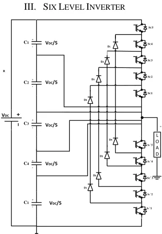
[image:1.612.324.562.224.430.2]The basic topology to realize the multilevel inverter is neutral point or diode clamped topology in which the dc voltage is split into n levels using (n-1) series connected capacitors across the supply. This topology requires 2(n-1) uni-directional blocking, bi-directional conducting fully controlled switches per phase. The six-level NPC topology requires 5 series connected capacitors across the supply. The proposed topology of three phase six level inverter is represented in figure 1.
Figure 1 Neutral point clamped six level inverter.
III. SIX LEVEL INVERTER
Figure 2 Single phase circuit of six-level inverter.
C1
C3
C5
D1
D2
D3
D4
D1'
D2'
D3' D4'
SC1 SC2 SC3 SC4 SC5
SC'5
SC'4
SC'3
SC'2
SC'1 C2
C4
Vdc
D1
D2
D3
D4
D1'
D2'
D3' D4'
SC1 SC2 SC3 SC4 SC5
SC'5
SC'4
SC'3
SC'2
SC'1
D1
D2
D3
D4
D1'
D2'
D3' D4'
SC1 SC2 SC3 SC4 SC5
SC'5
SC'4
SC'3
SC'2
SC'1 R Y B
VDC/5
L O A D
VDC/5
VDC/5
VDC/5
VDC/5 C1+
-C2+
-C3
+
-C1
+
-C4
+
-VDC
+
-V0 D1
D2
D3
D4
D1 D4
D3
D2
SC5
SC4
SC2 SC3
SC1
SC`4 SC`5
SC`3
[image:1.612.367.534.465.706.2]International Journal of Emerging Technology and Advanced Engineering
Website: www.ijetae.com (ISSN 2250-2459, ISO 9001:2008 Certified Journal, Volume 8, Issue 1, January 2018)
[image:2.612.367.528.137.364.2]177 The single phase circuit of six-level inverter is shown in figure 2, where IGBTs are used as switching devices. Each phase requires 10 switches to introduce six levels in the output voltage. The supply voltages V is divided into five equal levels, each of V/5 using five capacitors of same value connected in series and is connected as shown in figure 2. The six levels are 0, V/5, 2V/5, 3V/5, 4V/5 and V and are obtained by operating the switches in the desired sequence. It requires eight diodes in order to supply voltage at different levels to the load.
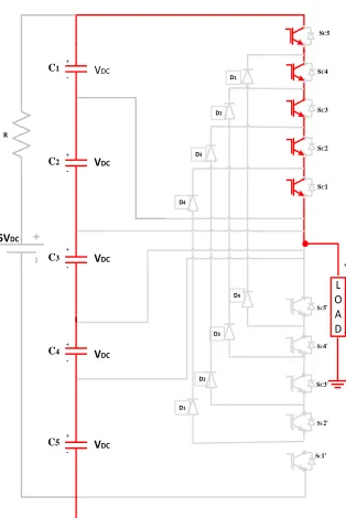
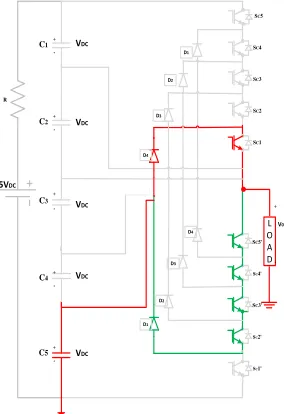
To obtain a voltage of V, the load will be connected across the supply as shown in figure 3, where all the top side switches need to conduct. The figure 4 represents the equivalent circuit for obtaining an output voltage of 4V/5. In order to get the output voltage 3V/5, the switches conducting is represented in figure5.
[image:2.612.87.244.356.591.2]The equivalent circuits for achieving an output voltage level of 2V/5, V/5 and 0 are given in figure 6, figure 7, and figure 8 respectively.
Figure 3 Single phase circuit for output voltage V.
Figure 4 Single phase circuit for output voltage 4V/5.
VDC
L O A D
VDC
VDC
VDC
VDC C1
+
-C2+
-C3
+
-C5+
-C4+
-5VDC
+
-V0 D1
D2
D3
D4
D1 D4
D3
D2
SC5
SC4
SC2 SC3
SC1
SC5'
SC3'
SC2'
SC1' R
SC4'
Figure 5 Single phase circuit for output voltage 3V/5. VDC
L O A D
C1
+
-C2
+
-C3
+
-C5 +
-C4
+
-5VDC
+
-V0 D1
D2
D3
D4
D1 D4
D3
D2
SC5
SC4
SC2 SC3
SC1
SC4' SC5'
SC3'
SC2' SC1' R
VDC
VDC
VDC
VDC
VDC
L O A D
VDC
VDC
VDC
VDC
C1
+
-C2+
-C3
+
-C5+
-C4+
-5VDC
+
-V0 D1
D2
D3
D4
D1 D4
D3
D2
SC5
SC4
SC2 SC3
SC1
SC4` SC5`
SC3`
SC2'
[image:2.612.370.520.390.603.2]International Journal of Emerging Technology and Advanced Engineering
Website: www.ijetae.com (ISSN 2250-2459, ISO 9001:2008 Certified Journal, Volume 8, Issue 1, January 2018)
178
VDC
L O A D
VDC
VDC
VDC
VDC
C1
+
-C2+
-C3
+
-C5+
-C4
+
-5VDC
+
-V0 D1
D2
D3
D4
D1 D4
D3
D2
SC5
SC4
SC2 SC3
SC1
SC4' SC5'
SC3'
SC2'
[image:3.612.103.240.136.357.2]SC1' R
Figure 6 Single phase circuit for output voltage 2V/5.
VDC
L O A D
VDC
VDC
VDC
VDC C1+
-C2
+
-C3
+
-C5+
-C4+
-5VDC
+
-V0 D1
D2
D3
D4
D1 D4
D3
D2
SC5
SC4
SC2 SC3
SC1
SC4' SC5'
SC3'
SC2'
SC1' R
Figure 7 Single phase circuit for output voltage V/5.
z
VDC
L O A D
VDC
VDC
VDC
VDC
C1+
-C2 +
-C3 +
-C5+ -C4
+
-5VDC
+
-V0 D1
D2
D3
D4
D1 D4
D3
D2
SC5
SC4
SC2 SC3
SC1
SC4'
SC5'
SC3'
SC2'
[image:3.612.374.515.138.347.2]SC1' R
Figure 8 Single phase circuit for output voltage 0.
Figure 9 Simulation diagram of six-level inverter.
[image:3.612.335.549.383.575.2] [image:3.612.99.241.390.597.2]International Journal of Emerging Technology and Advanced Engineering
Website: www.ijetae.com (ISSN 2250-2459, ISO 9001:2008 Certified Journal, Volume 8, Issue 1, January 2018)
179
TABLEI
OPERATION OF THE SWITCHES
Vdc/5 Vdc/4 Vdc/3 Vdc/2 Vdc 0
S
c1 1 1 1 1 1 0S
c2 1 1 1 1 0 0S
c3 1 1 1 0 0 0S
c4 1 1 0 0 0 0S
c5 1 0 0 0 0 0S
c1` 0 0 0 0 0 1S
c2` 0 0 0 0 1 1S
c3` 0 0 0 1 1 1S
c4` 0 0 1 1 1 1S
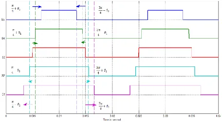
c5` 0 1 1 1 1 1The switches at the bottom are complementary signals to the top switches respectively. Hence the control signals designed for the top switches are given to the bottom switches using not logic.
Figure 10 Control signals for upper set switches.
IV. RESULTS
[image:4.612.331.558.138.332.2]The simulation is carried out in MATLAB Simulink environment on a 4-pole squirrel cage induction motor. The line to line voltage of five level and six level inverters are shown in figures 11 and 12 respectively. The frequency spectrum of the line voltages is also shown in the figures 11 and 12. Form the frequency spectrum it is observed that the harmonics present in the line voltage is reduced from 14.5% to 9.33% in six-level inverter.
Figure 11 Line voltage of five-level inverter.
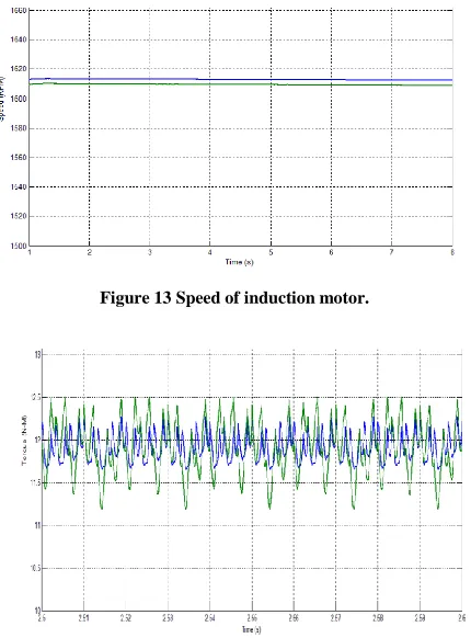
[image:4.612.63.275.153.341.2]The performance of the six-level inverter is checked on the same induction motor for the same load conditions. The figure 13 gives the information about the speed of the motor. It is observed that, there is no much increase in the speed of the machine. The figure 14 compares the torque information of the motor for five and six level inverters.
[image:4.612.58.286.402.527.2] [image:4.612.340.553.431.599.2]International Journal of Emerging Technology and Advanced Engineering
Website: www.ijetae.com (ISSN 2250-2459, ISO 9001:2008 Certified Journal, Volume 8, Issue 1, January 2018)
[image:5.612.61.276.139.430.2]180
Figure 13 Speed of induction motor.
Figure 14 Torque of the induction motor.
V. CONCLUSION
In this paper simulation of six-level inverter is presented and its performance is compared with the five-level inverter.
From the results it is observed that, the total harmonic distortion in the line voltage is decreased considerably in six-level inverter. There is no much change in the speed of the motor where as the ripple in the torque is considerably reduced.
REFERENCES
[1] L. G. Franquelo, J. L. Rodriguez, J. Leon, S. Kouro, R. Portillo, and M. A. Prats, " The age of multilevel converters arrives," IEEE Ind. Electron. Mag., vol.2, no. 2, pp. 28-39, Jun. 2008.
[2] H. Abu-Rub, J. Holtz, J. Rodriguez, and G. Baoming, "Medium-voltage multilevel converters - state of the art, challenges, and requirements in industrial application," IEEE Trans. Ind. Electr. vol. 57, no. 8, pp. 2581-2596, Aug. 2010
[3] M. Zahra, M. Jafari, Md. R. Islam and J. Zhu, "A comparative study on characteristics of major topologies of voltage source multilevel inverters," IEEE Innovative Smart Grid Tech., pp. 612-617, 2014. [4] P. Thongprasri, "A 5-level three-phase cascaded hybrid multilevel
inverter," IJCEE, vol. 3, no. 6, pp. 789-794, Dec. 2011
[5] Madhav D. Manjrekar Thomas A. Lipo “A hybrid multilevel inverter topology for drive applications” Applied Power Electronics Conference and Exposition, 1998, 523, 2
[6] T. Murali Krishna, C. Bhargav, “A new hybrid Multi Level Inverter to improve the performance of induction motor”, International Conference on Computation of Power, Energy Information and Communication (ICCPEIC), 2015 , pp.264-268.
[7] T. Murali Krishna, C. Bhargav, “Modeling and Performance Comparison of Two Different Hybrid Multi Level Topologies”, Procedia Computer Science, 85(2016) , pp.641-647.
[8] T. Murali Krishna, “Matlab Simulink Modeling of Hybrid Cascaded Five Level Inverter”, International Journal of Science and Research, 4(12), Dec 2015, pp.834-837.