© 2017, IRJET | Impact Factor value: 6.171 | ISO 9001:2008 Certified Journal | Page 610
Design of Rectangular Shaped slotted Micro strip Antenna for Triple
Frequency Operation for wireless application
V.H.Mokal
1, S.R.Gagare
2, R.P.Labade
31Student, Department of E&Tc Engineering, AVCOE, Maharashtra, India.
2Professor, Department of E&Tc Engineering, AVCOE, Maharashtra, India.
3HOD, Department of E&Tc Engineering, AVCOE, Maharashtra, India.
---***---Abstract -
This Paper represents the designing of the Tri- Band Rectangular Printed micro strip Antenna.Oneamongst the simplest feeding technique is
employed i.e. coaxial feeding technique for feeding the
antenna Tri band antenna is obtained by etching two quarter wavelength rectangular shaped slots inside the patch at the proper position to resonate over GSM, Bluetooth and Wi-MAX.The proposed antenna is realized on FR-4 dielectric substrate having a dielectric constant of 4.4 and loss tangent of 0.02, with dimensions of 46x38x1.6mm3. The design calculations are done for the frequency of 2.4 GHz. The designed antenna is simulated using EM simulation software CAD FEKO suite (7.0).The antenna covers the three bands of operation i.e. GSM (1.834-1.858GHz), Bluetooth (2.422-2.487GHz), Wi-Max (3.519-3.583GHz) with reflection coefficient ≤-10dB. The overall simulation results shows that the antenna gives good impedance matching at desired frequencies with VSWR≤2.Also the radiation pattern, efficiency,gain and impedance for all four frequencies are investigated using simulation results.
Key Words: — Coaxial feed, Global system for mobile communication (GSM), worldwide inter-operability for microwave access (Wi-MAX), FR4 Substrate, Multiband antenna, cadfeko.
1. INTRODUCTION
The Wireless connectivity has enabled a new mobile lifestyle filled with conveniences for mo-bile computing users. Consumers will soon demand the same conveniences throughout their digital home, connecting their PCs, personal digital recorders, MP3 recorders and players, digital camcorders and digital cameras, high-definition TVs (HDTVs), set-top boxes (STBs), gaming systems, personal digital assistants (PDAs), and cell phones, to connect to each other in a wireless personal area network (WPAN) in the home. But today’s wireless LAN and WPAN technologies cannot meet the needs of tomorrow’s connectivity of such a host of emerging consumer electronic devices that require high bandwidth.
A new technology is required to fulfill the requirements of high-speed WPANs. to hide several applications with common antenna might be referred as multiband antenna, rising variety of applications into same. Multiband systems avoid duplications of various antennas that may be
used for various applications. Small strip antennas with single band, dual band, triple band and quad band operations will be integrated into a same body of divergent structure, reducing quality and creating system compact [1].
Antennas with multiband operation along with multi-polarization have become trending topic for antenna design industries because of number of special benefits. In these days, antenna design has received significant importance. The design of multi-band antenna for 2.4 GHz Bluetooth IEEE 802.11 b/g (2.4-2.484 GHz), 3.5GHz Wi-MAX IEEE 802.16 (3.4-3.6GHz), 5.2/5.8GHz WLAN IEEE 802.11 a (5.15- 5.35 GHz and 5.725-5.825 GHz) and 5.5 GHz HIPERLAN2 (5.47-5.725 GHz) due to its wide range of usability in almost all commercial communication devices such as smart-phones, laptops, tablets, etc. is especially demanding [2].
In this work the designing of the Tri- Band Rectangular Printed micro strip Antenna presented, one of the best feeding techniques is used i.e. coaxial feeding technique for feeding the antenna. Tri band antenna is obtained by cutting two quarter wavelength rectangular shaped slots inside the patch at the proper position to resonate over GSM, Bluetooth, WI-MAX. The proposed antenna is realized on FR-4 dielectric substrate having a dielectric constant of FR-4.FR-4 and loss tangent of 0.02, with dimensions of 46x38mm2. The design calculations are for the frequency of 2.4 GHz. Single band operation of antenna obtained by using optimization of feed and patch length of the antenna. Then to get dual band and triple band operation the two rectangular shaped slots are etched from patch where current distribution is minimum. The optimized slot length and width are for slot1 dimensions are 10x2mm2 and for slot2 is 8x2mm2.Antenna
design is simulated using EM simulation software CADFEKO SUITE7.0.
2. Antenna Design
The Proposed rectangular shaped slotted antenna for triple frequency operation is shown in Fig.1 (a) which consists of patch of size 36.40x27.20mm2on one side of substrate. This radiating element patch is loaded with two rectangular shaped slots at the lower side of patch and at the left hand side of the patch respectively. The dimensions for slot1 are 10x2mm2 and for slot2 is 8x2mm2.Coaxial feeding is used of
© 2017, IRJET | Impact Factor value: 6.171 | ISO 9001:2008 Certified Journal | Page 611 substrate is used which has relative permittivity of 4.4 and
loss tangent is 0.02.The dimensions for ground plane is same as dielectric substrate [3]. The dimensions for proposed triple frequency antenna design are shown in Table 1.
Fig- 1: Geometry of the designed Tri band antenna (a) Top View, (b) Bottom View.
The antenna is designed for 2.4 GHz frequency and calculations for antenna design are done by using following “Equations (1-8)”.
Width of patch ( ):
Where, c is the speed of the light, fr is the resonant frequency and εr is the relative permittivity of the substrate.
Effective dielectric constant ( :
Where, εreff is the Effective dielectric constant ,εr is the dielectric constant of substrate,h is the Height of dielectric substrate and W is the Width of the patch.
Effective length(Leff):
Patch length (ΔL):
Length of substrate (Ls):
Width of substrate (Ws):
Distance of feed point from LP (X):
Distance of feed point from WP (Y):
Table- 1:Dimensions of Proposed Antenna
Parameters Values(mm)
Dielectric Substrate FR4
Dielectric constant (εr) 4.4
Substrate Height (h) 1.6
Feeding technique Co-axial
Patch Width (WP ) 36.40
Patch Length (LP ) 27.40
Length of Ground Plane
(Lsub = Lgnd) 38
Width of Ground Plane
(Wsub = Wgnd) 46
Feed Points(x,y) (6.12,7.17)
Lslot1xWslot1 10x2
Lslot2xWslot2 8x2
The antenna can generate the triple frequency bands at 2.45, 1.84, 3.55 GHz for different wireless applications. The surface current distribution for all three bands are shown in Fig.2.The rectangular patch with proper coaxial feed points generate first band (2.422-2.487GHz) for Bluetooth application. Then the rectangular slot1 is generated second band (3.519-3.583GHz) for WIMAX applications. Then after, for third band integration we have etched second slot2 which generated (1.834-1.858GHz) band for GSM application. Then A two rectangular quarter wavelength slots is etched in to the lower region of the radiating patch to and left hand side of radiating patch to resonate over Wi-Max band (3.4-3.6 GHz)and GSM band as shown in Fig1 [3].For Wi-Max band (3.4-3.6 GHz): center frequency (fw) = 3.5 GHz and λ/4 = 12.98 mm. For GSM band (1.834-1.858GHz GHz): center frequency (fw) = 1.84 GHz and λ/4 = 24.80 mm. where,
© 2017, IRJET | Impact Factor value: 6.171 | ISO 9001:2008 Certified Journal | Page 612
3. Simulation Results
In this section, the parametric analysis is performed to Tri band Antenna. Then achieved simulated results are analysed and discussed on various design aspects. We have considered Reflection Coefficient (S11) versus Frequency to judge the
performance of the antenna.
Fig-3: Reflection coefficient versus Frequency graph for the variations of feed position (X and Y) for Bluetooth Band.
Reflection coefficient versus Frequency diagram for the varieties of feed position (x and y) is appeared in Fig.3.Feed position controls the impedance matching. So we have done parametric investigation for feed positions. From Fig.3 we can state that, subsequent to performing number of reproductions for different feed positions, at that point at x = 2 mm and y = 7 mm from the focal point of the transmitting patch, a Bluetooth band from 2.405 - 2.475 GHz is accomplished. The parametric investigation of different sustain positions is as appeared in Fig.3. From the Fig.3 nourish position at x =2mm and y = 7mm, a most extreme reflection coefficient (S11) of - 38.5dB is accomplished. For other feed positions, S11 is not greater than exactly - 20dB.
Fig-4: Reflection coefficient versus Frequency graph for the variations of Length of patch (Lp)
Reflection coefficient versus Frequency diagram for the varieties of Length of patch (Lp) is appeared in Fig .4 By expanding the patch length (Lp), the middle recurrence of Bluetooth band continues diminishing. At Lp = 27.40mm, we accomplished the Bluetooth band with focus recurrence 2.44
GHz. As Length of the Lp expands, the lower recurrence of Bluetooth band moves left with changing peak. As we realize that Lp controls the thunderous recurrence. As we increment the Lp, Inductive reactance increments and Resonant band moved down that is from 2.36 to 2.54 GHz for Bluetooth band as appeared in Fig.4.coefficient versus Frequency graph for the variations of Length of patch (Lp) is shown in Fig .4.
Fig-5: Reflection coefficient versus Frequency graph for the variations of Length of slot1 (Lslot1)
The rectangular slot inserted below the feed point on the radiating patch is resonating at Wi-Max band (3.47-3.53 GHz). By changing the width of the slot the impedance bandwidth of the Wi-Max band can be controlled, while by increasing the length of the slot, the Wi-Max band shifts to the lower edge frequency with the varying peak. By parametric analysis of length and width the Wi-Max band 3.47-3.53 GHz with a peak -16 dB is obtained as shown in the Fig.5 and Fig.6.The optimized dimensions of the rectangular slot is Lslot=11mm and Wslot=2mm.
Fig-6: Reflection coefficient versus Frequency graph for the variations of width of rectangular slot1 (Wslot1).
© 2017, IRJET | Impact Factor value: 6.171 | ISO 9001:2008 Certified Journal | Page 613
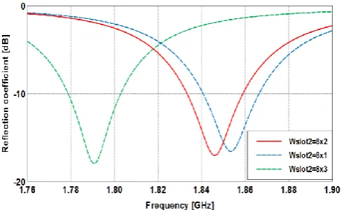
Fig-7: Reflection coefficient versus Frequency graph for the variations of Length of slot2 (Lslot2)
[image:4.595.306.560.60.220.2]By parametric analysis of length and width the GSM band 1.834-1.858 GHz with a peak -16 dB is obtained as shown in Fig.7 and Fig.8. The optimized dimensions of the rectangular slot isLslot=8mm and Wslot=2mm.
Fig-8: Reflection coefficient versus Frequency graph for the variations of width of rectangular slot2 (Wslot2).
The antenna has shown similar characteristics in case of reflection coefficient and VSWR to get the triple frequency operation. Based on the optimized parameters of the proposed tri band rectangular antenna, we obtained the bandwidths of an antenna ranging from for GSM (1.834-1.858GHz), for Bluetooth (2.422-2.487GHz), for Wi-Max (3.519-3.583GHz) as shown in Fig.9.
Fig-9: Reflection coefficient versus Frequency graph for the tri band antenna
Fig-10: Simulated (a) Graph of VSWR (≤2) vs. Frequency for Tri Band Antenna,(b)Graph of Impedance vs.
Frequency for tri band Antenna.
Fig .10.shows VSWR≤2 for all three bands are 1.33, 1.38, and 1.62 respectively. Fig.11 (a) shows the efficiency vs. frequency graph of the tri band antenna. Impedance vs. frequency graph is shown in Fig.11 (b) which shows that impedance for gsm, Bluetooth and wimax is 40.1Ω, 53.7Ω and 58.8Ω respectively.
Here it has been seen that for Bluetooth band, antenna efficiency is approximately 50% as shown in Fig. 11. And it is decreased after 3GHz.Fig.12. Shows the radiation pattern for elevation plane (E-plane or _=90) and azimuth plane (H-plane or _=0) at f=2.451,f=3.55 GHz , f= 1.84GHz and f=5.22GHz. It describes how an antenna directs the energy it radiates [11]. It shows an Omni-directional radiation pattern along the H-plane and a directional radiation pattern along the E-plane.
Fig-11: Simulated (a) Graph of Efficiency vs. Frequency for tri band, (b) Graph of Gain vs. Frequency for Tri Band
[image:4.595.39.288.73.227.2] [image:4.595.40.286.323.473.2] [image:4.595.312.558.478.655.2] [image:4.595.39.288.612.741.2]© 2017, IRJET | Impact Factor value: 6.171 | ISO 9001:2008 Certified Journal | Page 614
Fig-12: Simulated radiation patterns observed in E-plane and H-plane at (a) 2.45GHz (b) 3.55GHz.(c) 1.84GHz
Chart -1: Name of the chart
3. CONCLUSIONS
In this work, Design of Rectangular Shaped slotted Micro strip Antenna for Triple Frequency Operation for remote application is presented. This antenna covers triple frequency operation which includes GSM (1.834-1.858GHz), Bluetooth (2.422-2.487GHz), Wi-Max (3.519-3.583GHz) with Return loss≤ -10 dB and VSWR ≤ 2. For achieving Tri band operations two rectangular slots are etched from radiating patch and the location of feed point optimized in such way that the antenna operates in triple frequency bands. Also optimization of various parameters of antenna is done.
REFERENCES
[1] R. Garg, P. Bhartia, I. Bahl, and A. Ittipiboon, Microstrip
antenna design hand-book, Artech House, Boston,2001.
[2] K.P.Ray and Girish Kumar,Broadband microstrip
antenna,ArtechHouse,Boston, London.
[3] Rekha Labade, Dr. Shankar Deosarkar, Dr. Narayan
Pishoroty,”A Novel Integrated Bluetooth Dual Band
UWB Antenna for Wireless
Communication,”,International Journal of Microwave and Optical Technology vol .10(3),2015,pp195-201.
[4] C.A. Balanis,Antenna Theory, Analysis and Design
,second edition,John Wileyand Sons, New York,1997.
[5] Y. F. Cao, S. W. Cheung, and T. I. Yuk,”A Multi-band Slot
Antenna for GPS/WiMAX/WLAN Systems”, IEEE Transactions on Antennas and Propagation, vol.63(3), 2015,pp.952-958.
[6] S. Kumar and D. Chandra,”Multiband Star Shape Slotted
Microstrip Patch Antenna Design for wireless communications”,International Journal of Electronics and Electrical Engg.vol.3(5),2015,pp.402-405.
[7] A.B. Mutiara, R.Refianti, Rachmansyah,”Design Of
Microstrip Antenna For Wireless Communication At 2.4 GHz”, Journal of Theoretical and Applied Information Technology, vol.33(2), 2011,pp.184-192.
[8] Ogunlade Michael Adegoke, Charles Okand
aNyatega,”Design Of Dual Band Coax Patch Antenna For GSM and Bluetooth Applications, International journal of science and research”,vol.3(12),2014,pp.998-1002.
[9] Tze-hsuan chang and Jean-Fu Kiang,”Compact
Multi-Band H-Shaped Slot Antenna”, IEEE transactions on antennas and propagation,vol.6(8),2013,pp.101-109.
[10] Neetu, Savina Banasl, R K Bansal,”Design and Analysis of
Fractal Antennas based on Koch and Sierpinski Fractal Geometries”,International Journal of Advanced Research in Electrical, Electronics and Instrumentation Engineering vol.2(6), 2013,pp.2110-2116.
[11] Na.Nanthini, V.Dinesh , J.Vijayalakshmi, K.T.Dhivya,” A
Survey on Design of Multiband Monopole Antenna for Wireless Applications”,International Journal on Recent and Innovation Trends in Computing and Communication, vol.1(12),2013,pp.949 – 954.
[12] Sunakshi Puri,Kiranpreet kaur,Naveen Kumar,”A review
of antennas for wireless communication devices”,
International Journal of Electronics and Electrical Engg.vol.2(3),2014,pp.199-201.
[13] Anoop Varghese,Kazi Aslam,”Design and Simulation of
compound Fractal antennas for multiband Applications”, International Journal of Science and Research,vol.4(5),2015,pp.501-504
[14] F.-C. Ren*, F.-S. Zhang, J.-H. Bao, B. Chen, and Y.-C.
Jiao,”Compact Triple-frequency Slot Antenna for WLAN/WIMAX Operation”, Progress In Electromagnetic Research Letters, vol.26, 2011, pp.21-30.
[15] A. Bhattacharya, B. N. Biswas, , “A Parametric Study on
Microstrip Patch Antenna”, International Journal of Electronics & Communication Technology,vol.5( 2),2013..
[16] Lee, Y.-C. And J.-S. Sun, “A new printed antenna for