International Journal for Research in Applied Science & Engineering Technology (IJRASET)
ISSN: 2321-9653; IC Value: 45.98; SJ Impact Factor: 6.887 Volume 7 Issue IV, Apr 2019- Available at www.ijraset.com©IJRASET: All Rights are Reserved
558
Active Power Control of Wind Farm Equipped
DFIG Wind Turbines with Energy Storage System
M.L.V. Krishna Prasad
1, S. Srinivasa Rao
21, 2EEE Department, GITAM Institute of Technology, GITAM Deemed University, Visakhapatnam
Abstract: Large wind turbine are subjected harmful loads that arise from spatially uneven and temporarly unsteady on coming Wind such loads are known sources of fatigue damage that reduce the turbine operational life time, ultimately increasing the Cost of wind energy to users. In recent years, a substantial amount of studies has been focused on active power of a wind turbine in a wind farm,so in order to control power we need configure the dfig wind turbine by rotor side control,grid side control pitchangle control by using these controllers along with configuration of energy storage system in a wind farm so on achieving active power simulation should be done by using above controllers on matlab simulink
Keyword: doubly fed induction generator, energy storage system, wind farm control, pitch angle control, grid side controller, Rotor side controller, active power control.
I. INTRODUCTION
©IJRASET: All Rights are Reserved
559
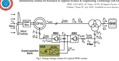
Fig.1. Energy storage system of a typical DFIG systemII. CONFIGURATION OF ENERGY STORAGE SYSTEM
[image:2.595.144.440.424.622.2]Fig. 1 shows Energy storage systems (ESSs) of a typical DFIG have a function of converting electrical energy from a power system network form that can be stored for converting back to electrical energy.ESS has numerous applications including portable devices, smart grid, building integration, energy efficiency, transport vehicles, and stationary renewable energy resources , only three different distributed ESSs for renewable generation systems were introduced as battery, super capacitor, and electrical dual layer capacitor consists of an energy source bank, an inductance and a two-quadrant DC/DC converter connected to the DC link. It also describes how the controller of the DC/DC buck-boost mode generates the gate signals for gate 1 and gate 2.
Fig. 2 control scheme of the ESS.
International Journal for Research in Applied Science & Engineering Technology (IJRASET)
ISSN: 2321-9653; IC Value: 45.98; SJ Impact Factor: 6.887 Volume 7 Issue IV, Apr 2019- Available at www.ijraset.com©IJRASET: All Rights are Reserved
560
III. CONTROL OF INDIVIDUAL DFIG WIND TURBINE
A. Control of the Rotor side controller
The main purpose of controlling rotor side converter is to control stator side active and reactive power independently. In order to implement the decoupled control method of active and reactive power, stator flux-oriented vector control scheme I adopted Stator voltage drop across resistance has been neglected as the stator resistance value are quite low in value. The DFIG is connected to stiff grid i.e. the frequency and amplitude of stator and grid voltage is assumed to be constant
Fig. 3. control scheme of the RSC
The RSC control scheme consists of two cascaded vector control structure with inner current control loops which regulates independently the d-axis and q-axis rotor currents, i.e. dr I and qr I, according to some synchronously rotating reference frame. The outer control loop regulates the stator active power and reactive power independently. The stator voltage orientation (SVO) control principle for a DFIG is described in the q-axis of the rotating reference frame is aligned to the stator voltage V = 0 and qs V = s V. From the stator side flux. In this study, the q-axis flux is regulated to zero for the de-coupled control of active and reactive power the q- axis is rotating 90o ahead of d-axis at synchronous speed in the direction of rotation the stator flux vector is aligned with the d-axis of the stator.
The above assumption in mathematical form will be as follows.
Vds = 0; Vqs= Vs
ϕds = ϕs : ϕqs = 0
This will reduce the active and reactive power to the following form. Ps= 3/2 (Vqs*iqs) Qs= 3/2 ( Vqs *ids)
B. Control of Grid side controller
Grid side converter control is used to regulate the voltage across the DC link and sometime also to compensate harmonics. This is a two-stage controller scheme which is achieved by grid voltage-oriented vector control scheme i.e. by aligning the dq- axis in the direction of grid voltage. The detailed discussion on this grid converter control scheme is proposed It can produce constant
©IJRASET: All Rights are Reserved
561
n otherFig .4 control scheme of GSC
To control the grid side converter, we adopt the grid side voltage-oriented vector control scheme. In this scheme. The rotating reference frame dq-axis will be rotated along the grid voltage. So Vdg will be equal to full grid voltage (Vdg= Vg) and Vqg will become 0. This will
reduce the power equation into the following form.
Pg= 3/2 (Vdg*idg); Qg= -3/2 (Vdg*iqg);
Dc link voltage control loop is developed on the principle of power balance on both side of GSC i.e. DC-link side and grid side. So in mathematical from it can be written as:
Vdc idc = Vdg i dg + Vqg iqg
As the d-axis of the reference frame is oriented towards the grid voltage, so Vqg component will be zero. Hence the above equation will reduce to
Vdc idc =Vdg idg
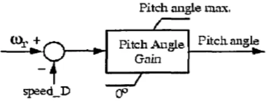
C. Pitch Angle Control scheme
The wind turbine blade pitch angle is controlled to regulate the output power from the wind turbine to match the load power demand and the power required to charge the embedded battery storage system. If the wind speed is high while the network load is small, pitch angle control is applied to reduce the output power from the DFIG so as to prevent the battery from being over-charged. For electromagnetic transients in power systems the pitch control is of less interest the wind speed is less than rotational speed by point D
where ωr and Pe (= Ps + Pg)
[image:4.595.168.452.619.728.2]International Journal for Research in Applied Science & Engineering Technology (IJRASET)
ISSN: 2321-9653; IC Value: 45.98; SJ Impact Factor: 6.887 Volume 7 Issue IV, Apr 2019- Available at www.ijraset.com©IJRASET: All Rights are Reserved
562
The lift and drag are dependent on the aerofoil of the blade and pitch angle of the blades θ. These forces can be expressed as an in-plane force, that causes the blade to rotate, and an out-of-in-plane force, that induces the nacelle and tower fore-aft motions. As the rotor spins, the rotational energy of the rotor is then transmitted via the drive trains to the generator, where the energy is converted into the electrical form. Notice that the in-plane and out-of-plane forces on the blade can be manipulated by the blade pitch angle. As a result, the rotational speed of the rotor and the motions of the blade and tower can be controlled by changing the blade pitch angles.so the active power is controlled by windfarm
IV. WIND FARM CONTROL
The Wind Farm Supervisory controller (WFSC) model that is a two-dimensional (2D) medium-fidelity wind farm model based on t equations that is developed for control purposes of power in a wind turbine design of a wind farm supervisory control algorithm requires a model of the wind farm system. The control objectives include requirements on the behaviour of the wind farm, as observed at the point of common coupling (PCC) between the wind farm and the onshore AC transmission grid. The model of the wind farm system should then encompass the wind turbines, the collection grid and the transmission to shore. The global inputs to the system are, primarily, the wind field, and voltage waveforms at the PCC and, secondarily, ocean waves. The global outputs are the active and reactive power – or equivalently, the current waveforms – at the point of common coupling with the onshore grid. Control system design is usually conducted using highly simplified models of the system dynamics. This is appropriate, as only certain primary features of the system are likely to impact stability and controllability, while secondary influences can be considered as disturbances. However, optimal control methods require development of a cost function, which may include the degradation of electrical and mechanical components under long‐term operation. It should not be taken for granted that the degradation of various components can be accurately represented by the outputs which are available from a highly simplified model.
The governing equation for power extraction is stated below:
P=F.V (1) The power losses of the wind turbine
Pei,max = Pmi,max− PLi = Psi,max + Pri,max (2)
The active power Ps of stator can be written in a synchronous dq reference frame
Ps = 3(vdsids + vqsiqs) 2
≈ 3 [ωsLm (iqsidr− idsiqr) + rs (i2ds + i2qs)] (3)
2
The active power Pr of rotor can be written in a synchronous dr frame Pr = 3 (vdridr + vqriqr)
2
≈ 3[−sωsLm (iqsidr− idsiqr) + rr(i2dr + i2qr)] (4)
2 Respective voltages of d-axis, q-axis of wind turbine
s = (ωs− ωr)/ωs (5)
ωr is the rotor speed of DFIG wind turbine. Here speed ‘s’ as follows
s = Pr − 3i2rrr (6)
Ps −3i2 srs
By neglecting stator, rotor copper loss 3i2
srs, 3i2rrr of the DFIG, wind turbine power can be estimated as,
Pr = −sPs. (7)
The maximum mechanical power Pm, max, DFIG wind turbine as
N
Pm, max = ∑ Pmi,max (8 )
t=1
Total active output power of rotor DFIG wind turbine as N
Pr max = ∑ Pei,max (9)
t=1
©IJRASET: All Rights are Reserved
563
NPs,max = ∑ Psi,max (10)
t=1
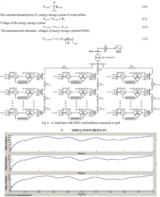
The constant demand power Pd ,energy storage system of wind turbine
Pess,d = Pe,max− Pd (11)
Voltage of the energy storage system:
Vi, min < Vessi < Vi, max (12)
The maximum and minimum voltages of energy storage systemof DFIG,
Pessi, max= ± CessVess dVessi (13)
[image:6.595.39.552.108.741.2]dt max
Fig. 6. A wind farm with DFIG wind turbines connected to grid
[image:6.595.57.545.517.738.2]V. SIMULATION RESULTS
International Journal for Research in Applied Science & Engineering Technology (IJRASET)
ISSN: 2321-9653; IC Value: 45.98; SJ Impact Factor: 6.887 Volume 7 Issue IV, Apr 2019- Available at www.ijraset.com©IJRASET: All Rights are Reserved
564
Fig.8.shows Voltages of wind turbines in wind farm
Fig.9.shows the generating active powers of wind turbines as we observe the figure the real power starts from initial power
©IJRASET: All Rights are Reserved
565
Fig.10.shows the active power outputs of wind farm here also power starts from initial 0.5position and vary from 0.5 to 3.5 atcertain time it suddenly falls by decreasing the minimum load on wind turbine and it gains its original position because of some harmonics wind farm of power quality
Fig.11.shows that active power is totally controlled in wind farm as we use the controllers such as RSC,GSC,angle pitch control Now there will be no losses found and also demand supply are in balance
VI. CONCLUSION
In this paper by configuration of DFIG turbine by controlling RSC, GSC, Energy storage system, Pitch angle control in a wind farm, by minimizing all losses to achieve active power can be controlled in a wind farm to supply quality power to end users.
REFERENCE
[1] B. Toufik, M. Machmoum, F. Poitiers, “Doubly fed induction generator with active filtering function for wind energy conversion system,” Proceedings of the European Conference on Power Electronics and Applications, Dresden; Germany, pp. 1-9, 2005
[2] X. F. Zhang, D. P. Xu, Y. B. Liu. Intelligent control for large-scale variable speed variable pitch wind turbines, Journal of Theory and Application, 2(3): 305-311, 2004.
[3] H. Z. Ye, Control of Wind Turbines, Beijing: Mechanical industry, 2005, chapter 8
[4] Http://www.mathworks.com/help/toolbox/physmod/powersys/ref/windturbine.html