© 2019, IRJET | Impact Factor value: 7.211 | ISO 9001:2008 Certified Journal | Page 7629
A Technical Approach to Flat Slab Multistorey Building under Wind
Speed of 39 m/s
Mariyam
1, Sagar jamle
21
M. Tech. Scholar, Department of Civil Engineering, Oriental University, Indore (M.P.), India.
2Assistant Professor, Department of Civil Engineering, Oriental University, Indore (M.P.), India
---***---Abstract -
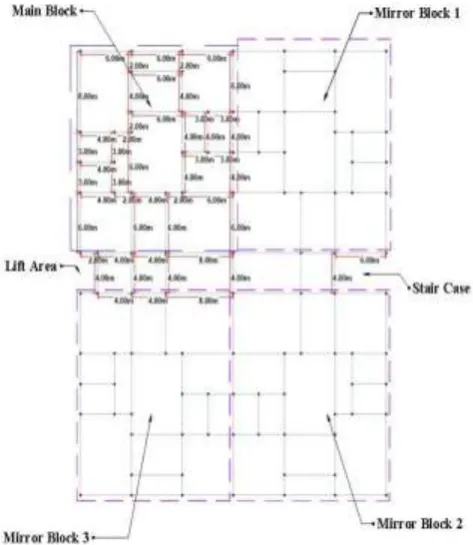
In this scenario, for multistorey building and skyscraper building, beam slab structure is not used in India, it is replaced by flat slab construction. The flat slab is a reinforced concrete slab which is directly supported on column so for aesthetic purpose, it is decent as well as it is efficient. Flat slab is more flexible as compared to R.C. slab so it’s advantages are more to design the flat slab. The flat slab has many advantages but the main problem is that the flat slab is weak against lateral loading such as wind and earthquake loading and with the help of equivalent frame method; the flat slab design is performed. In this work, taking the G+ 20 model building plan, which is rectangular in shape 36m x 44m in plan and this plan, is made with help of AutoCAD software. After fixing the plan, it has divided into different panels and each panels is designed by manual approach using equivalent frame method. This manual data inserted in Staad pro and analyze with providing shear wall at two different locations i.e. lift area and maximum stress in plate area of the building to minimize the same.Key Words: Column Stresses, Displacement, Equivalent frame method, Flat slab, Shear wall, Wind load.
1.INTRODUCTION
A concrete slabs are a common structural element which is used generally in modern structural buildings. These slabs are horizontal and it is generally made up of concrete or steel typically between 100 and 500mm thick as per requirement, are most often used floors and ceiling. The two types of slab are basically used in present time in structural building-
Common type slab Flat slab
The common type of slab is supported by beams and beam is attached with the columns, this types of construction called as simple beam slab construction. The slab which is directly supported by columns known as flat slab. Flat slab is a reinforced concrete slab supported by column, it may be added or not added drops or the column may be added column heads or without column heads. Drop is a local thickening of the slab in the region of the column. In the current scenario flat slab is used instead of beam column construction because of its advantages over beam column connections. In architectural point of view, flat slab are
[image:1.595.310.553.400.613.2]better, also it permits flexibility in building construction. It takes clear space, low height, easy framework and takes less time therefore flat slab buildings are used now-a-days in India. Flat slab structures are weak against lateral loading such as seismic loading and wind loading so that the design and analysis of flat slab is very important. Therefore analysing the different types of flat slab, provided shear wall at various points in different types of flat slab under wind load condition using software Staad pro. In present time flat slab buildings are used in high rise buildings because of its advantages as it reduces time, cost effective, easy installation and required the least storey height. To increase the performance of buildings wind load behaviour of building should be properly checked.
Fig -1: Flat Slab with Column Head
Mainly there are four types of flat slabs-
1. Simple flat slab 2. Flat slab added drop 3. Flat slab added column head
4. Flat slab added drop and column head
© 2019, IRJET | Impact Factor value: 7.211 | ISO 9001:2008 Certified Journal | Page 7630
building that reduces the available net clear ceiling height.Hence in warehouses, offices and public halls sometimes beams are avoided and slabs are directly supported by column are called flat slab.
2. Flat slab added drop - Drops are provided to increase the shear strength of slab. In flat slab bending moments are generated more near to the column, so that provided thickness to the slab near to the column by providing the drops. Sometimes the drops are known as the capital of the column.
3. Flat slab added column capital - The column capital is provided sometimes widened because to reduce the punching shear in the slab. The column head is provided in any angle for architectural purpose but for design purpose it is provided on 45 degree from vertical. Therefore in multistorey buildings, to reduce the punching shear column head is provided in the slab.
4. Flat slab added drop and column capital - Both are the combinations are the best for the design of flat slab because of the advantages of drops and column heads. This type of flat slab has high strength in shear. It is provided stiffening to the slab so that it reduces deflection.
2. OBJECTIVES
The main purpose is to find the economical model case to counteract wind forces and analysis is done using software Staad pro. So for this, different loads applied and parametric values obtained are considered and point of comparison on different models is as follows:
1. To find maximum Nodal Displacement in X Direction and Z Direction.
2. To show the maximum Axial Force in Column at Ground Level.
3. To compare maximum Shear Force in Column Sy and Sz for all model cases.
4. To relate maximum Compressive Stress in Column. 5. To find and observe maximum Tensile Stress in
Column.
6. To show and relate maximum Torsional Moment in Column for all model cases.
7. To obtain economical model among all model cases by observing and comparing their parametric values.
3.
STRUCTURE
CONFIGURATION
AND
METHODOLOGY
In this paper, taking G+20 model building with overall height of 80.01m with plan area (36mx44m) for four model cases. For this, the foundation depth is 3m and total height of each storey is 3.81m. Four different model cases are selected and modelled in Staad pro under basic wind speed of 39m/s with reference to Indian Standard code IS 875 Part 3. The main
aim is to design the flat slab so for this, firstly the whole plan is differentiated into different panels and each panels are design by manually using Equivalent Frame Method and data obtained is provided to Staad pro for the detailed analysis of the structure. All panels are designed on the basis of:
Roof
Exterior wall Interior wall
The data selected such as Grade of concrete M35, Grade of steel Fe 415 is selected. The bar diameter selected as 12 mm with a Clear cover of 25 mm throughout the structure. Unit wt. of brick taken as 20 KN/m3, height of floor selected as 3.81m for all the subsequent levels. Thickness of external wall and internal wall are 0.228m and 0.15m respectively with plaster thickness of 0.24m with 20KN/m3 unit weight. Also, parapet height of 0.75 m is used. 10 mm mortar unit weight 0.42 KN/m3 for ceiling and 10 mm thick terrazzo flooring with weight of 0.24 KN/m2 is selected. Column size selected as 500 mm x 400 mm by hit and trial method. For load consideration, live load for floor and roof are 3.5KN/m2 and 1.6KN/m2.
DESIGN OF FLAT SLAB FOR PANEL SIZE 6X8
Step1- Thickness of Flat Slab-
Equivalent Frame M/D = Modification Factor (M.F) = 33.8 Overall depth (D) = Span/Ratio = 8000/33.8 = 237 mm D Approx. = 294 mm
Let Effective Depth (d) = D - (Dia. of Bar / 2) - Clear Cover = 294 - (12/2) - 25
In Longer Direction (dl) = 263mm or .263m
In Shorter direction (ds) = Dl – Dia. of Bar = 263 - 12 ds = 251mm or .251m
Step 2 - Load Calculation 1 - Dead Load
A - Self load of slab = D x unit weight of concrete =.294 x 25 = 7.4 KN/m2
B - Plate area load
1) Parapet wall load
PWL = (thickness x height x unit weight of brick) / plate area PWL = [(.228 x 20 + .024 x 20) x .75] / (6 x 8) = .078 KN/m2
C- for 10 mm mortar both side of roof and floor = .42 KN/m2
D- Terrazzo floor tiles load 10 mm thick = 0.24 KN/m2
Total dead load
For roof level dead load = 7.4 + .078 + .42 + 0.24 = 8.1 KN/m2
load-© 2019, IRJET | Impact Factor value: 7.211 | ISO 9001:2008 Certified Journal | Page 7631
For roof level = 8.1 + 1.6 = 9.7 KN/m2Total Factored Load -
For roof level = 1.5 x 9.7 = 14.6 KN/m2
Step 3 - Calculation of stiffness and alpha c (αc) Along longer direction
For slab
Ks = (4 x E x I)/LL = (4 x E x 12665474635) /8000 = 6332737 x E ∑ks = 2 x 6332737 = 12665475
For column
Kc = (4 x E x I)/CH = (4 x E x 4166666667) / 3810 = 437474453 x E
∑kc = 2 x 437474453 = 8748906
Then, αC = ∑kc / ∑ks = (8748906 / 12665475 x E) = .7 Along shorter direction
A. For slab
Ks = (4 x E x I) / LL = ( 4 x E x 16887299514) / 6000 =
11258200 E
∑ks = 2 x 11258200 E = 22516399 B. For column
Kc = (4 x E x I) / CH = (4 x E x 2666666667) / 3810 = 2799650 E
∑kc = 2 x 2799650 = 5599300
Then, αC = ∑kc / ∑ks = 5599300 / 22516399 = .25
Step-4 Check for correction due to pattern loading If ratio of Live Load and Dead Load is greater than 0.5, then pattern loading required
Live Load / Dead Load < = .5
At roof level = live load / dead load = 1.6 / 8.1 = .2 (not Required)
Step-4 Check for correction due to pattern loading If ratio of Live Load and Dead Load is greater than 0.5, then pattern loading required
Live Load / Dead Load < = .5
At roof level = live load / dead load = 1.6 / 8.1 = .2 (not required)
Step- 5 Total moment calculation In longer direction
Ln = 7.5 M L2 = 6 M Ln2 = 56.25 m
Mo = (W x Ln x L2) / 8 or (w x L2 x Ln2) / 8 = (14.6 x 6 x 56.25) / 8 = 613
In shorter direction
Ln = 5.6 m L1 = 8 m Ln2 = 31.36 m
Mo = (W x Ln x L1) / 8 or (w x L1 x Ln2) / 8 = (14.6 x 6 x 31.36) / 8 = 456
Step-6 Column strip and middle strips In longer direction
Column strips
A- 2(.25 x L2) = 2(.25 x 6000) = 3000 mm B- 2(.25 x L1) = 2(.25 x 8000) = 4000 mm
Lesser value will be taken (a or b) column strip = 3000 mm Middle strips = L2 - column strips = 6000 - 3000 = 3000 mm
In shorter direction Column strips
A- 2 (.25 x L1) = 2(.25 x 8000) = 4000 mm
B- 2 (.25 x L2) = 2(.25 x 6000) = 3000 mm Lesser value will be taken (a or b) column strip = 3000 mm
Middle strips = L1 - column strip = 8000 - 3000 = 5000 mm Step- 7 Reinforcement along longer direction Moment in longer direction
[image:3.595.309.557.220.423.2]Pt % =
Table 1: Moment in Longer Direction
Mu Mucn = .65 x .75 x Mo = .65 x .75 x 613 = 300
Mucp = .35 x .6 x Mo = .35 x .6 x 613 = 130
Mumn = .65 x Mo - Mucn = .65 x 613 – 300
= 100
Mump = .35 x Mo - Mucp = .35 x 613 -130 = 86
Pt .42 % .17 % .13 % .12 % Total
Ast
(Pt x b x d) /100 = (.42 x 263 x 3000) / 100 = 3310
(Pt x b x d) /100 = (.17 x 263 x 3000) / 100 = 1340
(Pt x b x d) /100
= (.13 x 3000 x 263) / 100 = 1025
(Pt x b x d) /100 = (.12 x 3000 x 263) / 100 = 946
Ast/m 1105 447 342 316
Step-8 Reinforcement along shorter direction
Table 2 : Moment in Longer Direction: For roof
Mu Mucn = .65 x .75 x Mo = .65 x .75 x 456 = 223
Mucp = .35 x .6 x Mo = .35 x .6 x 456 = 96
Mumn = .65 x Mo -Mucn = .65 x 456 – 22 = 75
Mump = .35 x Mo -Mucp = .35 x 456 – 96 = 64 Pt .34 % .15 % .12 % .06 % but
take .12 % Total
Ast
(Pt x b x d) /100 = (.34 x 251 x 3000) / 100 = 2560
(Pt x b x d) /100 = (.15 x 251 x 3000) / 100 = 1130
(Pt x b x d) /100 = (.12 x 5000 x 251) / 100 = 1505
(Pt x b x d) /100 = (.12 x 5000 x 251) / 100 = 1505
Ast/m 855 380 300 300
Step- 9 Check for two way shear or punching shear Shear force calculation
Vu = (L1 x L2 - critical section area) x factored load = (6 x 8 - .750 x .650) 14.6 = 690 KN
Bo= 2 x critical section area = ( 650 + 750) x 2 = 2803 Bo x d = 2803 x 251 = 702610
[image:3.595.308.557.478.689.2]© 2019, IRJET | Impact Factor value: 7.211 | ISO 9001:2008 Certified Journal | Page 7632
From IS code 456 -2000 page no 58 (cl. 31.6.3.1)Ks =1.3
Tau c = .35 x (fck).5 = 1.47 Tau c' = 1.47
For roof Tau c = .98 N/mm2
4. LOADING DETAILS
With the help of IS 456-2000 and IS 875 Part-3, the load selected along with their combinations with appropriate partial factor of safety. Load taken in this work are as follows:
1. Wind in + X direction 2. Wind in - X direction 3. Wind in + Z direction 4. Wind in - Z direction 5. D.L.
6. L.L.
7. 1.5 (D.L + L.L)
8. 1.2 (D.L. + L.L ± Wind X) 9. 1.2 (D.L. + L.L ± Wind Z) 10. 1.5 (D.L. ± Wind X) 11. 1.5 (D.L ± Wind Z) 12. 0.9 (D.L. ± 1.5 Wind X) 13. 0.9 (D.L. ± 1.5 Wind Z)
5. STRUCTURE MODELING
In this work, the G+20 Model building plan selected and designed simple flat slab and added drop flat slab which is further extended into two other cases on the basis of stress location in flat slab. Different types of model are shown in Table 3.
Table 3 : Different Building Model Cases
Model No. Name of models
Model M1 G+20 storey building with simple flat slab providing shear wall around the lift
Model M2 providing shear wall around the lift and the G+20 storey building with simple flat slab core
Model M3 G+20 storey building with added drop flat slab providing shear wall around the lift
Model M4 slab providing shear wall around the lift and G+20 storey building with added drop flat the core
Fig -2: Plan of Building Model Case
[image:4.595.317.554.110.383.2] [image:4.595.356.509.414.734.2]© 2019, IRJET | Impact Factor value: 7.211 | ISO 9001:2008 Certified Journal | Page 7633
Fig -4: Maximum Stress Occurring in Model Case M1Fig -5: Shear Wall Location in G + 20 Storey Building
6. RESULTS AND DISCUSSION
[image:5.595.82.249.104.405.2]When building analyzed under the influence of Wind load, the four different model case’s result parameters are compared to find the most economical model therefore as per the objective of this work, the results obtained are shown in graphical form as well as in tabular form for different parameters which are as follows:
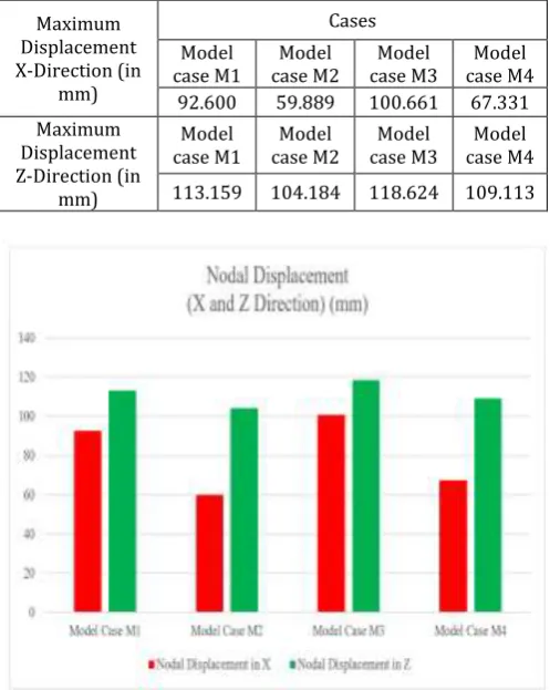
Table 4: Nodal Displacement in X and Z Direction
Maximum Displacement X-Direction (in
mm)
Cases Model
case M1 case M2 Model case M3 Model case M4 Model 92.600 59.889 100.661 67.331 Maximum
Displacement Z-Direction (in
mm)
Model
case M1 case M2 Model case M3 Model case M4 Model 113.159 104.184 118.624 109.113
Chart -1: Nodal Displacement in X and Z Direction
In model case M2, the nodal displacement in X and Z Direction is least among all of four Model Cases M1, M3 and M4 in both directions.
Table 5:Axial Force in Column at Ground Level
Cases
Axial Force In Column At Ground Level (KN) Model case
M1
Model case M2
Model case M3
[image:5.595.309.558.224.536.2]© 2019, IRJET | Impact Factor value: 7.211 | ISO 9001:2008 Certified Journal | Page 7634
Chart -2:Axial Force in Column at Ground Level [image:6.595.304.557.105.382.2]The value of the Axial Force in column at ground level in Model Case M2 is 7874.994 KN, this value is lesser among all the model cases such as Model Case M1, M3 and M4.
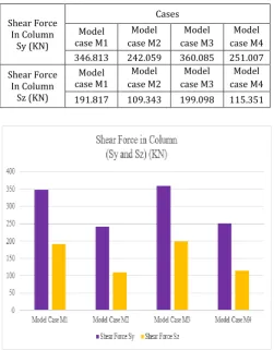
Table 6:
Shear Force in Column Sy and Sz
Shear Force In Column
Sy (KN)
Cases Model
case M1
Model case M2
Model case M3
Model case M4 346.813 242.059 360.085 251.007 Shear Force
In Column Sz (KN)
Model case M1
Model case M2
Model case M3
Model case M4 191.817 109.343 199.098 115.351
Chart -3:Shear Force in Column Sy and Sz
Comparing all Model Cases, Model Case M2 shows least values among all for Shear Forces Sy and Sz. Hence the optimum case will be Model Case M2.
Table 7: Maximum Compressive Stress in column
Cases
Maximum Compressive Stress In Column (N/mm2) Model case
M1
Model case M2
Model case M3
Model case M4 61.598 40.82 63.985 42.221
Chart -4:Maximum Compressive Stress in Column
[image:6.595.36.288.379.701.2]The Maximum Compressive Stress in column seems to be minimum in Model Case M2 with a value of 40.82 N/mm2 as compared to other models cases such as Model Case M1, M3 and M4.
Table 8: Maximum Tensile Stress In Column
Cases
Maximum Tensile Stress In Column (N/mm2) Model case
M1
Model case M2
Model case M3
Model case M4 49.24 36.974 51.098 38.317
[image:6.595.307.566.480.747.2]© 2019, IRJET | Impact Factor value: 7.211 | ISO 9001:2008 Certified Journal | Page 7635
The Maximum Tensile Stress in column observed maximum [image:7.595.35.287.168.425.2]in Model Case M3 which is 51.098 N/mm2 and lesser in Model Case M2, the value is 36.974 N/mm2 which is minimum among all the Model Cases.
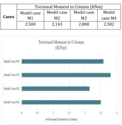
Table 9: Torsional Moment In Column
Cases
Torsional Moment in Column (KNm) Model case
M1
Model case M2
Model case M3
Model case M4 2.500 2.143 2.808 2.582
Chart -6:Maximum Torsional Moment in Column
The Torsional Moment in column is maximum in Model Case M3 which is 2.808 KNm but lesser in model case M2 and this value is smaller in all the Model Cases.
7. CONCLUSIONS
The some conclusions are written below according to some results parameters for four different cases:
1. In Model Case M2, the value of Nodal Displacement in X direction is least among all the Model Cases and the maximum value of Nodal Displacement in Model Case M3.
2. The Nodal Displacement in Z direction is minimum in Model Case M2 and Model Case M4 but maximum in model case M3.
3. The Axial Force in column at ground level is maximum in Model Case M3 but minimum in model case M2 and M4.
4.
The Shear Force in column in Y direction is minimum in Model Case M2 which is lesser among all the model cases. Shear Force value in Z direction is maximum in Model Case M3 but lesser in Model Case M2 and M4. 5. The Maximum Compressive Stress in column is least inModel Case M2 but maximum in model case M3. Maximum Tensile in Column is least in model case M2 and model case M4.
6. The torsional moment in column is maximum in model case M3 but least in model case M2 and M1.
7. Observing all the result parameters Model Case M2 seems to be efficient among all four cases. Hence in G+20 storey building with simple flat slab providing shear wall around the lift and the core should be preferred.
ACKNOWLEDGEMENT
I would like to thank my guide Mr. Sagar Jamle, Assistant Professor, Department of Civil Engineering, Oriental University, Indore (M.P.). He always gave me unremitting and enthusiastic support in this work. He gave me excessive support and self-determination as an M.Tech scholar.
REFERENCES
[1] Amit A. Sathawane, R. S. Deotale, (2012), “Analysis and
Design of Flat Slab and Grid Slab and Their Cost Comparison”, International Journal of Engineering Research and Applications, ISNN: (2231-5721), Vol.1, Issue 02, pp. 122-126.
[2] Anuja Walvekar, H.S. Jadhav, (2015), “Parametric Study
of Flat Slab Building with and without Shear Wall to Seismic Performance”, International Journal of Research in Engineering and Technology, ISNN: (2321-7308), Vol. 04, Issue 4, pp. 601-607.
[3] Dr. Uttamasha Gupta, Shruti Ratnaparkhe, Padma Gome,
(2012), “Seismic Behaviour Of Buildings Having Flat Slabs With Drops”, International Journal Of Emerging Technology And Advanced Engineering, ISNN:(2250-2459),Vol. 02, Issue 10, pp. 416-421.
[4] Kaulkhere R.V, Prof. G.N Shete, (2017), “Analysis and
Design of Flat Slab with Various Shapes”, International Journal of Scientific Development and Research, ISNN: (2455-2631), Vol. 2, Issue 05. pp. 538-544.
[5] M. K. Devtale, S. S. Sayyed, Y. U. Kaulkarni, P. G. Chandak,
(2016), “Comparison Of Seismic Response Between Flat Slab Building And Regular Frame Building”, International Journal Of Advancement In Engineering Technology, Management & Applied Science, ISNN: (2349-3224), Vol. 03, Issue 06, pp. 104-111.
[6] Miguel Fernandez Ruiz, Yaser Mirzai and Aurello
Muttoni, (2013), “Post Punching Behaviour Of Flat Slab”, ACI Structural Journal, Title No. 110-S66, pp.801-812.
[7] Mohammed Imran, M. Visweswara Rao, Dr. Jammi
© 2019, IRJET | Impact Factor value: 7.211 | ISO 9001:2008 Certified Journal | Page 7636
[8] Nasr Z. Hassan, Mostafa A. Osman, Awad M. EI-Hashimy,
Heba K. Tantawy (2017), “Enhancement Of Punching Shear Strength Of Flat Slabs Using Shear -Band Reinforcement”, Housing And Building National Research Centre, pp. 1-7.
[9] P. Manjunath and Yogeendra R. Holebsgilu (2016),
“Seismic Analysis of Multi Storey Building With Flat Slab Resting On Plain And Sloping Ground”, Bon Fring International Journal Of Man Machine Interface, ISNN:(2277-5064), Vol. 04, Issue special, pp. 20-25.
[10] P. Srinivasulu, A. Dattatreya Kumar, (2015), “Behaviour
of RCC Flat Slab Structures under Earthquake Loading,” International Journal Of Engineering & Science Research, ISNN :( 2277-2685), Vol. 05, Issue 07, pp.821-829.
[11] R. S. More, V. S. Sawant, (2013), “Analysis of Flat Slab”,
International Journal Of Science And Research, ISNN: (2319-7064), Vol. 4, Issue 07, pp. 98-101.
[12] S. S. Patil, Rupali A. Sigi, (2014), “Flat Slab Construction