A Study on Transient Analysis of Bridge Deck Slab under the Action of
Moving Load
Chinmay Thakur, Sumit Pahwa
---***---
Abstract:- Present study includes the modal and transient analysis of bridge deck slab subjected to moving load by using ANSYS software. The modal analysis results are compared with previous literature and close for solution. The parametric study is in form of deflection, stress and strain for variation of model’s dimension. The study reveals that Finite Element Method can be applicable and reliable tool for analysis of bridge deck slab. The aim of this study is to evaluate the damage of the selected deck slab and evaluating the cracking and crushing of deck under cyclic wheel loads. Nonlinear analysis of structural element using ANSYS Workbench is carried out.Keywords: Bridge deck slab, Finite Element Method, Natural Frequency, 3D-FE modelling, IRC loading. Introduction
The bridge assessment can be done by conducting laboratory experiments, field tests and also through analytical means. Fatigue is a progressive deterioration of a structure by crack growth, due to a series of stress variations (cycles) resulting from the application of repeated loads, such as induced in bridge components under traffic loads and heavy vehicle crossings. Bridge decks must withstand one of the most damaging types of live load forces i.e., the concentrated and direct pounding of truck wheels. A primary function of the deck is to distribute these forces in a favourable manner to the support elements below. The current study restricts to analytical method of performance evaluation. In analytical method the accuracy of the result depends upon the ability to simulate the problem. In reality, most of the problems are nonlinear in nature. Hence nonlinear analysis is an effective tool to simulate the exact problem. Nonlinearity may be geometric or material nonlinearity. A structure could encounter either one of the above or combination of both.
COMPUTER MODELING USING ANSYS
The whole bridge and then designed the model in ANSYS workbench represent a numerical method, which provides solution to problems that would otherwise be difficult to obtain. The numerical analysis investigations were performed
with commercial software ANSYS 14.5. Modelling the complex behaviour of reinforced concrete, which is both non
homogeneous and anisotropic, is a difficult challenge in the finite element analysis of civil engineering structures. Where a special three-dimensional eight nodded solid isoperimetric element, Solid 65 is developed. It models the nonlinear response of brittle materials and is based on a constitutive model for the triaxial behaviour of concrete. Solid 65 allows the presence of four different materials within each element; one matrix material (e.g., concrete) and a maximum of three independent reinforcing materials.
The concrete material is capable of directional integration point cracking and crushing besides incorporating plastic and creep behaviour. The reinforcement (which also incorporates creep and plasticity) has uniaxial stiffness only. In the current study, Solid 65 element available in ANSYS is employed for obtaining the ultimate load carrying capacity and for determining the behaviour of concrete bridge under service load.
LOADING REPRESENTATION
Nonlinear analysis of bridge model was carried out under the simulated wheel load of IRC Class A wheeled vehicle as per IRC 6−2000. Special technique is employed for representing a moving load or a vehicle. This method uses the transient solution analysis of the ANSYS, placing the loads on one specified set of nodes at a time. The program divides the axle weights in half and applies two-wheel loads at a distance equal to half the vehicle width onto either side of the centreline
of vehicle travel. Figure 1 shows IRC Class A train of vehicle. Accumulating fatigue damage caused by passing vehicles is
needed for fatigue safety evaluation of existing concrete bridges. The fatigue life can also express in terms of number of years. The design traffic is considered in terms of cumulative number of standard axles.
Cumulative number of standard axles is computed as per IRC 37 (2001). The following points are considered.
I. Axle loading will be used for the calculation of stress ranges as per IRC –Class A loading.
Figure 1: IRC-Class A Train of vehicle (Habeeba et. Al. 2015)
PROBLEM STATEMENT
There is limited work has been done on finding dynamic response of bridge. Vibration due to moving loads on bridge causes larger effect on deck slab. It is difficult to identify effect of the significant parameters that governs the response. Due to vibrations change in stresses, strains and deflection occurs. Hence finding dynamic behaviour of deck slab is very important. In this research we are finding these stresses, strains and deflection when velocity, span, depth and load frequency changes, the modal analysis is carried out in software. The vehicle load of IRC Class A traveling along the deck in a direction parallel to span. Damping in both the bridge and the vehicle is ignored. The vehicle is assumed to remain in contact with the deck. So that it will become helpful in future for analysis of deck slab. The design of bridges arise the dynamic response is very much significant in bridge to obtain vibration free and disturb free bridge structure.
DECK SLAB DETAILS
Table 1 shows the dimension of deck slab for different spans and effective depths.
Span (m) Width (m) Depth (m)
6 15 0.30 0.36 0.42 0.48
4 15 0.30 0.36 0.42 0.48
Modelling of Bridge Deck structure in Ansys
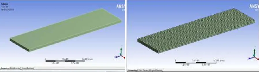
Two types of bridge deck structure modelled in Ansys and optimize variations as per depth variations. Bridge Deck slab panels of size 15m X 4m, 15m X 6m, with thickness 0.30m, 0.36m, 0.42m and 0.48m are modelled in Ansys. Material
properties of deck slab are Young’s Modulus = 25000 MPa, Poisons ratio = 0.15, Density = 2549 Kg/m3. The width of slab is
[image:2.595.74.525.618.744.2]15 m whereas span and depth vary as 4m and 6m respectively. Meshing is developed to slab for accuracy of results, boundary conditions are one end of slab is fixed and other having pinned support.
Figure 4: Boundary Conditions of Bridge Deck Structure
MODAL ANALYSIS
The modal analysis is carried out for different span lengths for varying depths. Table 2 shows natural
[image:3.595.67.529.350.508.2]Frequencies of the deck slab. The result shows that as the depth increases natural frequencies are also increases.
Table 2: Natural Frequencies due to Modal Analysis
Dimensions
(m) Depth(m)
Natural Frequencies
Mode 1 Mode 2 Mode 3 Mode 4 Mode 5 Mode 6
15 X 4
0.3 3.3073 9.0254 10.382 17.87 22.263 23.057
0.36 3.5982 9.0242 12.323 22.293 26.432 33.402
0.42 4.1799 10.491 14.21 25.885 30.491 34.039
0.48 4.7529 11.938 16.084 29.418 33.562 34.639
15 X 6
0.3 3.015 7.3245 7.554 16.486 18.684 26.714
0.36 3.604 8.723 9.0379 19.62 22.329 31.403
0.42 4.1871 10.098 10.507 22.694 25.928 35.49
0.48 4.7612 11.522 11.956 25.882 29.465 38.138
TRANSIENT ANALYSIS
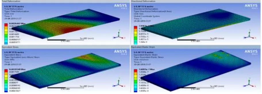
The transient analysis is carried out for different span lengths for varying depths under moving loads. The loading is applied in form of IRC type loading and vehicle load is 1200 Kg. As load moves on slab deflection, stress and strain develops in it.
[image:3.595.69.525.586.750.2]Figure 6: Total Deformation of Slab 15m x 4m x 0.30m Figure 7: Stress of Slab 15m x 4m x 0.30m
[image:4.595.75.521.288.712.2]TEST RESULTS AND DISCUSSION
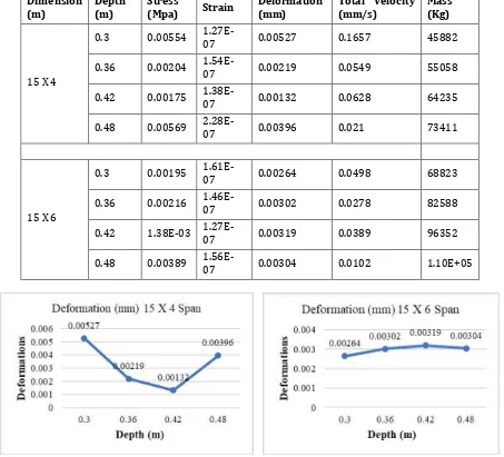
Table 3: Transient Analysis Results of Slab model in Ansys
Dimension
(m) Depth (m) Stress (Mpa) Strain Deformation (mm) Total Velocity (mm/s) Mass (Kg)
15 X 4
0.3 0.00554 1.27E-07 0.00527 0.1657 45882
0.36 0.00204 1.54E-07 0.00219 0.0549 55058
0.42 0.00175 1.38E-07 0.00132 0.0628 64235
0.48 0.00569 2.28E-07 0.00396 0.021 73411
15 X 6
0.3 0.00195 1.61E-07 0.00264 0.0498 68823
0.36 0.00216 1.46E-07 0.00302 0.0278 82588
0.42 1.38E-03 1.27E-07 0.00319 0.0389 96352
0.48 0.00389 1.56E-07 0.00304 0.0102 1.10E+05
[image:4.595.73.526.297.708.2]
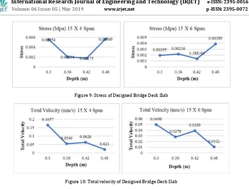
Figure 9: Stress of Designed Bridge Deck Slab
[image:5.595.48.560.52.442.2]
Figure 10: Total velocity of Designed Bridge Deck Slab
[image:5.595.74.525.446.588.2]
Figure 11: Strain of Designed Bridge Deck Slab
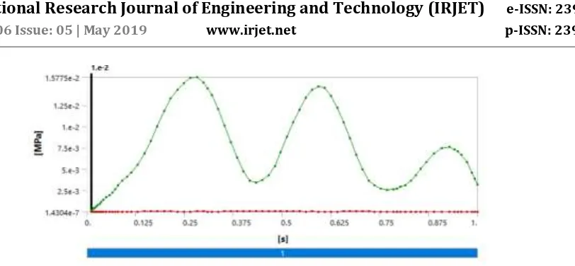
Figure 13: Stress Vs Time of Slab 15m X 4m X 0.30m
As depth increases changes occur in deck slab that is deflection is decreases in 15x4 (m) slab at depth 0.42. For span 6m, maximum deflection is 0.00319 mm when depth is 0.42m. At 15x4 (m) slab minimum deflection found is 0.00132 mm at 0.42 depth. So as per study slab 15x4 (m) gives better deflection results at depth 0.42. Maximum Stress found in Deck slab 15 x 6 (m) is 0.00569 and 15 x 4 (m) is 0.00389, but in 4 m span slab stress decreases as per depth increases, Maximum strain developed for 4 m width deck slab span is 0.00000022779, for 6m width deck slab span 0.00000015588, for IRC Class A loading.
IX. CONCLUSION
The dynamic response of a bridge deck slab to moving vehicles was studied. The dynamic response was measured in terms of the normalized deflection, stress and strain. Following conclusions were drawn on the basis of results obtained from this study of simplified models of the bridge and the vehicle.
Deformation, Shear stress and Normal stresses are considerably reduced by increasing depth of deck.
The modal analysis result shows that, as the depth increases, the natural frequencies are also increases.
The transient analysis results show that deflection, stress and strain decrease as depth increase.
As span increases deflection, stress and strain decreases.
REFERENCES
1. Amsa M, Divya G, "Design and Analysis of Path Over Bridge by Using Staad Pro", International Research Journal of Engineering and Technology (IRJET), Volume: 05, Issue: 09, Sep 2018.
2. Helu Yu, Bin Wang, "Road Vehicle-Bridge Interaction considering Varied Vehicle Speed Based on Convenient Combination of Simulink and ANSYS", Hindawi, Shock and Vibration, Volume 2018, Article ID 1389628, 14 pages. 3. Bhagwant Singh Siddhu, "Design and Analysis of Bridge Structure using Staad-Pro", Journal of Engineering and
Applied Sciences, 2017.
4. Prashant S. Patil, "A comparative study of steel girder bridge with FRP using ANSYS", VJER-Vishwakarma Journal
of Engineering Research, Volume 1 Issue 2, June 2017.
5. Ajinkya S. Shah, Srinivas R. Suryawanshi, "Response of steel deck bridge under influence of moving load using FRP", IJSDR, Volume 1, Issue 5, 2016.
6. Iqra Zaffar, Priyanka Singh, "Analysis and Design of Deck Slab Bridge", Journal of Civil Engineering and Environmental Technology, Volume 3, Issue 6; April-June, 2016, pp. 517-522.
7. Habeeba A, Sabeena M.V, "Fatigue Evaluation of Reinforced Concrete Highway Bridge", International Journal of Innovative Research in Science, Engineering and Technology, Vol. 4, Issue 4, April 2015.
8. Prateek S. Hundekar, Dilip K. Kulkarni, "Performance Based Analysis of Bridge Deck for Distinctive Girder Types", International Journal of Engineering Research & Technology (IJERT), Vol. 3 Issue 8, August - 2014.
9. Shwetha, Siddesha H, "Vibration Response of Deck Slab", Proceedings of Twelveth IRF International Conference,
31st August 2014.
10. Tincy Anna Yohannan, Indu Susan Raj, "Finite Element Analysis of Bridge Deck Slab", International Journal of Science, Engineering and Technology, Volume 3, Issue 5, 2015.
11. Ji Jing, Zhang Wenfu , Zhao Wenyan, Yuan , Chaoqing Yang, “Analysis and Comparison on Dynamic Characteristics