MPSO BASED SOLUTION FOR OPF PROBLEM INCORPORATING VARIOUS FACTS DEVICES FOR
IEEE STANDARD BUS SYSTEMS
Associate Professor/E.E.E., Sri Krishna College of Technology, Coimbatore
ARTICLE INFO ABSTRACT
This paper proposes an approach for optimal power flow (OPF)
power system stability because Stability is one of the important constraints in a power system operation. Often trial and error heuristics methods are used to improve the stability of the power system, but that can be costly
simulation to determine a transiently secure operating point is presented. The methodology involves a stability constrained Optimal Power Flow (OPF).
adopted to realize the OPF process. The method is programmed in MATLAB and implemented to a fourteen
(or near optimal) operating points in different cas
OPF problem with improvement in the power system stability also.
Copyright©2017, Dr. Nanda Kumar. This is an open access article distributed under the Creative Commons Att distribution, and reproduction in any medium, provided the original work is properly cited.
INTRODUCTION
NY physical system that is designed or operated to perform certain pre
performing those functions in satisfactory manner, be stable at all times for sudden disturbances with a margin of safety. Wh physical system is large and complex such as a typical modern interconnected system, investigation of stability requires ana sophistication in terms of techniques employed and practical experience in interpreting the results properly.
system to reestablish the initial state (or one practically identical) after any disturbance or interruption manife
from the initial parameter values for the system’s operation. A distinction is made between static and dynamic stability, tha between the ability to reestablish the initial state after small and strong disturbances, respectively. S
condition for the reliable operation of a power system.
In reality the stability problem appears to be an OPF
the normal OPF voltage and thermal constraints. The concept of optimal power flow, introduced by Dommel and Tinney in the early 1960’s, has received great attention since its early application to power systems analysis. OPF is a nonlinear optimiza problem, where a specific objective function
power system. Active power loss in the transmission system is to be minimized as the objective function, while Automatic Volt Regulator (AVR) operating values, On-Lo
equipments are selected as control variables.
Optimization algorithm. Particle Swarm Optimization (PSO
Dr. Eberhart and Dr. Kennedy in 1995, inspired by social behavior of bird flocking or fish schooling. PSO optimizes a problem having a population of candidate solutions, here dubbed
to simple mathematical formulae over the particle's position and velocity.
Load Flow Calculations
The load flow calculation is important to compute the power flow between the buse used for load flow calculation.
*Corresponding author: Dr. NandaKumar, E.
Associate Professor/E.E.E., Sri Krishna College of Technology, Coimbatore
ISSN: 0975-833X
Article History:
Received 17th October, 2016 Received in revised form 25th November, 2016
Accepted 10th December, 2016
Published online 31st January,2017
Key words:
MPSO-Modified Particle Swarm Optimization; FACTS-Flexible A.C. Transmission Systems; OPF-Optimal Power Flow.
Citation: Dr. Nanda Kumar, 2017. “Mpso based solution for opf problem incorporating various facts devices for ieee standard bus systems
Journal of Current Research, 09, (01), 45929-45935.
RESEARCH ARTICLE
MPSO BASED SOLUTION FOR OPF PROBLEM INCORPORATING VARIOUS FACTS DEVICES FOR
IEEE STANDARD BUS SYSTEMS
*Dr. Nanda Kumar, E.
Associate Professor/E.E.E., Sri Krishna College of Technology, Coimbatore
ABSTRACT
This paper proposes an approach for optimal power flow (OPF)
power system stability because Stability is one of the important constraints in a power system operation. Often trial and error heuristics methods are used to improve the stability of the power system, but that can be costly and imprecise. A new methodology that eliminates the need for repeated simulation to determine a transiently secure operating point is presented. The methodology involves a stability constrained Optimal Power Flow (OPF). Particle swarm optimization (PSO)
adopted to realize the OPF process. The method is programmed in MATLAB and implemented to a fourteen-bus test power system. The results show the ability of the proposed method to find optimal (or near optimal) operating points in different cases. This paper proposes this novel approach to solve OPF problem with improvement in the power system stability also.
is an open access article distributed under the Creative Commons Attribution License, which distribution, and reproduction in any medium, provided the original work is properly cited.
physical system that is designed or operated to perform certain pre-assigned tasks in a steady state must, in addition to performing those functions in satisfactory manner, be stable at all times for sudden disturbances with a margin of safety. Wh physical system is large and complex such as a typical modern interconnected system, investigation of stability requires ana sophistication in terms of techniques employed and practical experience in interpreting the results properly.
system to reestablish the initial state (or one practically identical) after any disturbance or interruption manife
from the initial parameter values for the system’s operation. A distinction is made between static and dynamic stability, tha between the ability to reestablish the initial state after small and strong disturbances, respectively. S
condition for the reliable operation of a power system.
In reality the stability problem appears to be an OPF-like problem, in which stability can be viewed as a constraint in addition to aints. The concept of optimal power flow, introduced by Dommel and Tinney in the early 1960’s, has received great attention since its early application to power systems analysis. OPF is a nonlinear optimiza problem, where a specific objective function must be optimized while satisfying operational and physical constraints of the electric power system. Active power loss in the transmission system is to be minimized as the objective function, while Automatic Volt
Load Tap Changer (OLTC) positions and number of reactive power compensation equipments are selected as control variables. This paper proposes an OPF problem which is realized by means of Particle Swarm Optimization algorithm. Particle Swarm Optimization (PSO) is a population based stochastic optimization technique developed by Dr. Eberhart and Dr. Kennedy in 1995, inspired by social behavior of bird flocking or fish schooling. PSO optimizes a problem having a population of candidate solutions, here dubbed particles, and moving these particles around in the search
to simple mathematical formulae over the particle's position and velocity.
The load flow calculation is important to compute the power flow between the buses. In our method Newton raphson method is
Associate Professor/E.E.E., Sri Krishna College of Technology, Coimbatore.
International Journal of Current Research
Vol. 9, Issue, 01, pp.45929-45935, January, 2017
INTERNATIONAL
Mpso based solution for opf problem incorporating various facts devices for ieee standard bus systems
MPSO BASED SOLUTION FOR OPF PROBLEM INCORPORATING VARIOUS FACTS DEVICES FOR
Associate Professor/E.E.E., Sri Krishna College of Technology, Coimbatore
This paper proposes an approach for optimal power flow (OPF) problem in order to improve the power system stability because Stability is one of the important constraints in a power system operation. Often trial and error heuristics methods are used to improve the stability of the power and imprecise. A new methodology that eliminates the need for repeated simulation to determine a transiently secure operating point is presented. The methodology involves a Particle swarm optimization (PSO) algorithm is adopted to realize the OPF process. The method is programmed in MATLAB and implemented to a bus test power system. The results show the ability of the proposed method to find optimal es. This paper proposes this novel approach to solve OPF problem with improvement in the power system stability also.
ribution License, which permits unrestricted use,
assigned tasks in a steady state must, in addition to performing those functions in satisfactory manner, be stable at all times for sudden disturbances with a margin of safety. When the physical system is large and complex such as a typical modern interconnected system, investigation of stability requires analytical sophistication in terms of techniques employed and practical experience in interpreting the results properly. The ability of a power system to reestablish the initial state (or one practically identical) after any disturbance or interruption manifested as a deviation from the initial parameter values for the system’s operation. A distinction is made between static and dynamic stability, that is, between the ability to reestablish the initial state after small and strong disturbances, respectively. Stability is a necessary
like problem, in which stability can be viewed as a constraint in addition to aints. The concept of optimal power flow, introduced by Dommel and Tinney in the early 1960’s, has received great attention since its early application to power systems analysis. OPF is a nonlinear optimization must be optimized while satisfying operational and physical constraints of the electric power system. Active power loss in the transmission system is to be minimized as the objective function, while Automatic Voltage ad Tap Changer (OLTC) positions and number of reactive power compensation This paper proposes an OPF problem which is realized by means of Particle Swarm ) is a population based stochastic optimization technique developed by Dr. Eberhart and Dr. Kennedy in 1995, inspired by social behavior of bird flocking or fish schooling. PSO optimizes a problem by particles, and moving these particles around in the search-space according
s. In our method Newton raphson method is
INTERNATIONAL JOURNAL OF CURRENT RESEARCH
Newton raphson method is commonly used technique for load flow calculation. The real and reactive power in each bus is computed using equation 1 & 2.
N
k
ik ik
ik ik
k i
i
V
V
G
B
P
1
sin
*
cos
*
*
………..(1)
N k
ik ik
ik ik
k i
i V V G B
Q
1
cos * sin
*
* ………..(2)
where,
N
is the total number of buses,V
i &V
k are the voltage ati
&k
bus respectively,
ik is the angle betweeni
&k
bus,ik
G
&B
ik are the conductance and susceptance value respectively. After computing the power flow between the lines, the amount of power to be generated for the corresponding load with low cost is identified using PSO. In our method, there are two stages of PSO and a neural network is used. Here, PSO is used for generating training dataset to train the neural network. In the first stage, the amount of power generated by each generator for a particular load is computed using PSO and in the second stage, the bus where the FACTS controller is to be connected is identified and using this data, the neural network is trained. From the output of neural network, the amount of power to be generated by each generator for the given load and the location of FACTS controller to be connected are obtained.Stage 1: Computation of Power to be generated for
P
GiThe amount of power to be generated by each generator is estimated using PSO. The process that takes place in PSO is generation of initial particle, evaluation function and updating the particles. The first step is generating the initial particle by PSO.
Generating Initial Particle
First the total number of generators connected in the system is identified and then the amount of power generated by each generator is calculated by satisfying two constraints. The initial particles to be generated by using PSO are
P
G1,
P
G2,...
P
GD
.The two constraints that must be satisfied for generating the particle are given below.
Constraint1: d l
D
i
Gi
P
P
P
1
………..(3)
where,
P
Gi is the total power generated,P
d is the total power demand,P
l is the total power loss,D
is the total number of generator.Constraint2 :
P
Gimin
P
Gi
P
Gimax ………(4)where,
P
Gimin andP
Gimax is the minimum and maximum real power to be generated byi
th generator.The initial particles are generated by satisfying the above two constraints and after generating the initial particle, the next step is evaluation function.
Evaluation Function
The evaluation function is used to evaluate the initial particle generated in the above step. Here, the cost function is taken as the evaluation function.
Evaluation function,
C
F
E
……….(5)Where
Fuel cost,
D
i
Gi i Gi i
i
b
P
c
P
a
F
1
2
)
*
*
(
……….(6)EmissionCost
D
i
i Gi i Gi
i P P
E
1
2
*
*
………(7)where,
a
i,b
i andc
i are the cost coefficients of thei
th generator,P
Gi is the real power of thei
th generator, and
i,
i andi
are the coefficients of thei
th generator emission Characteristics.Updating Initial Particles
Updating the particles is an important process in PSO. In this stage, the initial particles generated in section 3.2.1 are updated and then the fitness values are calculated. The particles are updated using the equation given below.
pbest[
]
-
present[
]
2
*
(
)
*
[
]
[
]
*
)
(
*
1
]
[
]
[
v
c
rand
c
rand
gbest
present
v
………..(8)]
[
]
[
]
[
present
v
present
……….(9)]
[
v
is the particle velocity,present
[
]
is the current particle,pbest
[
]
andgbest
[
]
are best fitness value and best valuefrom any particle in the population respectively,
rand
(
)
is the random number between
0
,
1
andc
1
,c
2
are learning factors. By using the above equation, initial particles are updated and a new particle is generated. The total number of new particles is generated based on the number of iterations applied. Then, the evaluation function is applied to the newly generated particles and the particle with low cost is selected as the best particle.Repeat the above process by randomly generating new set of generator values and the process are repeated for
n
times, so thatn
set of data is generated. The
n
set of data generated from PSO are as follows. n GnD Gn Gn D G G G D G G G C C C P P P P P P P P P S . . ... . . ... ... 2 1 2 1 2 22 21 1 12 11 ...………(10)
From the above generated data, the minimum cost function is taken as the power generated by the generator with low cost.
Placement of Facts Controllers
FACTS controllers are used to improve the power flow between the lines. There are different types of FACTS controllers are used. Here, UPFC is used to improve the power flow between the lines, and the amount of voltage and angle to be injected due to the addition of UPFC controllers are calculated using PSO. Due to the addition of UPFC, some real and reactive power is added to the buses where the UPFC needs to be connected. The real and reactive power injected due to the addition of UPFC is calculated using the equations 11, 12, 13 & 14.
k inj
new inj i inj new inj k inj k inj k i G V V V G B G V V P cos * * * * 2 * sin * cos *
* 2 ……….(11)
i inj
i qnew inj i new k
i
V
G
B
V
I
Q
*
*
sin
*
cos
*
……….(12)
i inj
new inj
i inj
k
k
V
V
G
B
P
*
*
cos
*
sin
……….(13)
i inj i inj
inj k
k
V
V
G
B
Q
*
*
sin
*
cos
……….(14)where,
P
i,
P
k,
Q
i,
Q
k are the real and reactive injecting powers from and to bus respectively,I
q is the transformer reactive current,V
inj and
inj are the injecting voltage and angle respectively,G
gik
G
new
,B
new
bik
B
. ………..(15)The above real and reactive power injected values are added to the starting and ending buses where the UPFC is connected, respectively in 1 &2. In the second stage, the voltage and angle to be injected are calculated by using PSO.
Optimal Settings of facts devices
all possible single and multiple contingencies, the optimization problem will have to be solved using Fuzzy Controlled Genetic Algorithm technique.
The objective function for this work is, Objective = minimize {SOL and IC}
4
1 1
)
(
k kmaxn
k k M
C
P
P
a
SOL
………(16)where,
m- Number of single contingency considered n- Number of lines
ak- weight factor=1.
Pk- real power transfer on branch k.
Pkmax- maximum real power transfer on branch k. IC - Installation cost of FACTS device
SOL- Represents the severity of overloading
)
$
(
75
.
153
71
.
0
0015
.
0
S
2S
US
KVAR
C
TCSC
………(17))
$
(
22
.
188
2691
.
0
0003
.
0
S
2S
US
KVAR
C
UPFC
………...(18)where, S - Operating range of UPFC in MVAR
S
Q
2
Q
1 ………..(19)Q1 – MVAR flow through the branch before placing FACTS device. Q2 - MVAR flow through branch after placing FACTS device. The objective function is solved with the following constraints
Voltage Stability Constraints
VS includes voltage stability constraints in the objective function and is given by,
=
0 0.9 <
< 1.1
0.9 −
< 0.9
− 1.1
> 1.1
………..(20)
Vb - Voltage at bus B
FACTS Devices Constraints
The FACTS device limit is given by,
−0.5
<
< 0.5
………..(21)−200
≤
≤ 200
………..(22)Where,
XL - original line reactance in per unit
XTCSC - reactance added to the line where UPFC is placed in per unit Qsvc- reactive power injected at SVC placed bus in MVAR
Power Balance Constraints
While solving the optimization problem, power balance equations are taken as equality constraints. The power balance equations are given by,
Σ PG = Σ PD + PL ……….(23)
Where, ΣPG– Total power generation ΣPD– Total power demand
PL – Losses in the transmission network
= ∑/ / /
/[
(
−
) +
(
−
)]
.………(25)where
Pi– Real power injected at bus i. Qi– Reactive power injected at bus i.
θi ,θk– The phase angles at buses i and k respectively.
Ei,Ek– Voltage magnitudes at bus i and k respectively.
Gik, Bik– Elements of Y – bus matrix.
RESULTS AND DISCUSSION
[image:5.595.144.454.221.444.2]The proposed technique was implemented in the working platform of MATLAB 7.11 and tested using both IEEE 14 & 30 bus systems. The IEEE 14 bus system used in our proposed method is shown in Figure 1.
Fig.1. IEEE standard 14 bus system
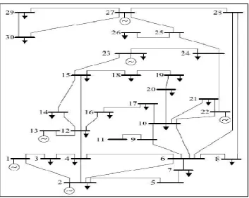
The IEEE 30 bus system used in our proposed method is shown in Figure 2.
[image:5.595.122.476.490.772.2]
Line Data
Table 1. Line Data
[image:6.595.137.461.301.492.2]Bus Data
Table 2. Bus Data
Bus No. Bus No. R (p.u.) X (p.u. 1/2 B (p.u. Line code = 1 for lines > 1 or < 1 tr. tap at bus No.
1 2 0.0192 0.0575 0.0264 1
1 3 0.0452 0.1852 0.0204 1
2 4 0.057 0.1737 0.0184 1
3 4 0.0132 0.0379 0.0042 1
2 5 0.0472 0.1983 0.0209 1
2 6 0.0581 0.1763 0.0187 1
4 6 0.0119 0.0414 0.0045 1
5 7 0.046 0.116 0.0102 1
6 7 0.0267 0.082 0.0085 1
6 8 0.012 0.043 0.0045 1
6 9 0 0.208 0 0.978
6 10 0 0.556 0 0.969
9 11 0 0.208 0 1
9 10 0 0.11 0 1
4 12 0 0.256 0 0.932
12 13 0 0.14 0 1
12 14 0.1231 0.2559 0 1
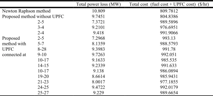
Comparison with & without UPFC
Table 3. Comparison with & without UPFC
Total power loss (MW) Total cost (fuel cost + UPFC cost) ($/hr) Newton Raphson method 10.809 809.7812
Proposed method without UPFC 9.7451 804.8386
Proposed method with UPFC connected at
2-5 7.3721 989.5896
3-4 9.2101 976.6951
2-4 9.418 991.9066
2-5 7.2968 993.13
5-7 8.1359 988.5793
8-28 9.3983 991.78
9-10 9.7263 992.051
10-17 9.1633 985.535
14-15 9.2339 991.633
10-17 9.138 986.0894
19-20 8.6614 985.9431
21-23 8.0017 977.1855
24-25 9.4722 992.0179
25-27 9.229 989.6654
Conclusion
IEEE 14 &30 bus systems and FACTS controller used in our method is SVC, TCSC and UPFC. In this paper, the proposed method was tested for IEEE 30 bus system and FACTS controller used in our method is UPFC. The proposed method is compared with Newton raphson method and proposed method without UPFC controller. In Newton raphson method power loss is 10.809 MW and cost is 809.7812 $/hr, but in our method (UPFC connected between bus 2 & 5) power loss is 7.3721 MW and cost is
Bus No.
Bus code
Voltage magnitude
Angle degree
Load Generator Injected MVAR P.u. Degree MW MVAR MW MVAR Qmax Qmin
1 1 1.06 0 0 0 0 0 0 0 0
2 2 1.043 0 21.7 12.7 40 0 -40 50 0
3 0 1 0 2.4 1.2 0 0 0 0 0
4 0 1.06 0 7.6 1.6 0 0 0 0 0
5 2 1.01 0 94.2 19 0 0 -40 40 0
6 0 1 0 0 0 0 0 0 0 0
7 0 1 0 22.8 10.9 0 0 0 0 0
8 2 1.01 0 30 30 0 0 -10 60 0
9 0 1 0 0 0 0 0 0 0 0
10 0 1 0 5.8 2 0 0 -6 24 19
11 2 1.082 0 0 0 0 0 0 0 0
12 0 1 0 11.2 7.5 0 0 0 0 0
13 2 1.071 0 0 0 0 0 -6 24 0
[image:6.595.119.478.548.710.2]989.5896 $/hr, in our method cost increases because due to the installation of UPFC in the system. From the above results it is clear that our method has reduced the power losses as well as the total cost in the system.
REFERENCES
Abido, M. A. 2002. “Optimal power flow using particle swarm optimization,” Elect. Power Energy Syst., no. 24, pp. 563–571. Anibal, T. Azevedo, Aurelio R. L. Oliveira, Marcos J. Rider and Secundino Soares, 2010. "How to Efficiently Incorporate Facts
Devices in Optimal Active Power Flow Model", Journal of Industrial and Management Optimization, Vol. 6, No. 2, pp. 1-17, May.
Ch. Rambabu, Y.P. Obulesu and Ch. Saibabu, 2011. "Improvement of Voltage Profile and Reduce Power System Losses by using Multi Type Facts Devices", International Journal of Computer Applications, Vol. 13, No. 2, pp. 37-41.
Chung, T.S., Y.Z.Li, “A Hybrid GA approach for OPF with consideration of FACTS devices,” IEEE Power Eng.Rev.21 (2) (2001) pp.47-50.
Devaraj, D. and Narmatha Banu, R. 2010. "Optimal Power Flow for Steady State Security Enhancement using Enhanced Genetic Algorithm with FACTS Devices", Asian Power Electronics Journal, Vol. 4, No.3, pp. 83-89, Dec.
Gerbex, S.R.Cherkaoui, A.J. Germond, “optimal location multi-type FACTS Devices in a power system by means of genetic algorithms,” IEEE transactions on power systems, Volume 16, Issue 3, 2001, pp.537-544.
Granville, S. 1994. “Optimal reactive dispatch through interior point methods,” IEEE Trans. Power Syst., vol. 9, no. 1, pp. 136– 146, Feb.
Happ, H. H. 1977. “Optimal power dispatch-A comprehensive survey”, IEEE Trans. Power Apparat. Syst.,vol. PAS-90, pp. 841-854.
IEEE working group, “Description and bibliography of major economic- security functions part-II and III, IEEE Trans. Power Apparat. Syst., vol. PAS-100, pp. 215-235,1981.
Keerati Chayakulkheeree and Weerakorn Ongsakul, "Multi-Objective Optimal Power Flow Considering System Emissions and Fuzzy Constraints", GMSARN International Journal Vol. 1, pp. 1 - 6, 2008.
Mithun, M. Bhaskar and Sydulu Maheswarapu, 2011. "A Hybrid Genetic Algorithm Approach for Optimal Power Flow", TELKOMNIKA, Vol. 9, No. 1, pp. 209-214, April.
Murali, D. and Rajaram, M. 2010. "Active and Reactive Power Flow Control using FACTS Devices", International Journal of Computer Applications, Vol. 9, No.8, pp. 45-50, Nov.
Numphetch Sinsuphun, Uthen Leeton, Umaporn Kwannetr, Dusit Uthitsunthorn, and Thanatchai Kulworawanichpong, 2011. "Loss Minimization Using Optimal Power Flow Based on Swarm Intelligences", ECTI Transactions on Electrical Eng., Electronics, and Communications, Vol. 9, No. 1, pp. 212-222.
Pizano-Martinez, A., C. R. Fuerte-Esquivel and D. Ruiz-Vega, 2010. “Global transient stability-constrained optimal power flow using an OMIB reference trajectory,” IEEE Transactions on Power Systems, vol. 25, no.1, pp. 392-403, February. Evolutionary Computation, vol. 12, no. 2, pp. 171-195, April 2008.
Sanjoy Kumar Saha, "Reliability Contingency Analysis by Static Synchronous Series Compensator in Optimal Power Flow",
International Journal of Computer and Electrical Engineering, Vol. 2, No. 5, pp. 908-911, Oct 2010.
Swarup, K. S. 2006. "Swarm intelligence approach to the solution of optimal power flow", J. Indian Inst. Sci., Vol.86, pp. 439– 455, Oct.
Vijayakumar Krishnasamy, 2011. "Genetic Algorithm for Solving Optimal Power Flow Problem with UPFC", International Journal of Software Engineering and Its Applications, Vol. 5 No. 1, pp. 39-50, Jan.
Vijayakumar, K. 2011. "Optimal Location of FACTS Devices for Congestion Management in Deregulated Power Systems",
International Journal of Computer Applications, Vol. 16, No. 6, pp. 29-37, Feb.
Yuehui Chen et al., “Evolving Wavelet Neural Networks for System Identification”, Proceeding of International Conference on Electrical Engineering, .279-282, 2000.
Zarate-Minano, R., Van Cstem, T., Milano, F. and Conejo, A. J. 2010. “Securing transient stability using time-domain simulations within an optimal power flow,” IEEE Transactions on Power Systems, vol. 25, no. 1, pp. 243-253, February.
Zhang, Q. and Benveniste, A. 1992. “Wavelet Networks”, IEEE Trans. On Neural Networks, Vol.3, No.6, 889-898.