Bandwidth-Efficient Wireless
Multimedia Communications
LAJOS HANZO,
SENIOR MEMBER, IEEECommencing with the brief history of mobile communications and the portrayal of the basic concept of wireless multimedia communications, the implications of Shannon’s theorems regard-ing joint source and channel codregard-ing for wireless communications are addressed. Following a brief introduction to speech, video, and graphical source coding as well as the cellular concept, a rudimentary overview of flexible, reconfigurable, mobile radio schemes is provided. We then summarize the fundamental con-cepts of modulation, introduce an adaptive modem scheme, and argue that third-generation transceivers might become adaptively reconfigurable under network control in order to meet backward compatibility requirements with existing systems and to achieve best compromise among a range of conflicting system requirements in terms of communications quality, bandwidth requirements, com-plexity and power consumption, robustness against channel errors, etc.
Keywords— Cellular communications, channel coding, graph-ical source coding, modern transceiver, modulation, multimedia system schematic, multimode speech system, speech source cod-ing, video-phone systems, video source codcod-ing, wireless channels, wireless communications, wireless multimedia communicator.
NOMENCLATURE
ACI Adjacent channel interference.
ACTS Advanced communications technologies and services.
ADPCM Adaptive differential pulse code modula-tion.
AGC Automatic gain control.
AMPS Advanced Mobile Phone System. ATM Asynchronous transfer mode. AWGN Additive white Gaussian noise.
BCH Bose–Chaudhuri–Hocquenghem, a class of forward error-correcting codes.
BER Bit error rate, the number of bits received incorrectly.
Manuscript received June 20, 1997. This work was supported in part by the Engineering and Physical Sciences Research Council, UK, in part by the Commission of the European Communities, Brussels, Belgium, in part by Motorola ECID, Swindon, UK, and in part by the Virtual Centre of Excellence in Mobile Communications, UK.
The author is with the Department of Electrical and Computer Sci-ence, University of Southampton, Southampton SO17 1BJ UK (e-mail: [email protected]).
Publisher Item Identifier S 0018-9219(98)04469-7.
B-ISDN Broad-band ISDN.
BPS Bits per symbol.
BS Base station.
CC Chain coding.
CCI Cochannel interference. CDMA Code division multiple access. CELP Code excited linear prediction.
CIF Common intermediate format frames, con-taining 352 pixels vertically and 288 pixels horizontally.
CSI Channel state information.
CT Cordless telephone.
CT2 British cordless telephone system. DAB Digital audio broadcasting.
DAMPS Digital AMPS.
DCA Dynamic channel allocation. DCC Differential chain coding.
DCT Discrete cosine transform, which trans-forms data into the frequency domain. Commonly used for video compression by removing high-frequency components in the video frames.
DECT Digital European cordless telephone. DFT Discrete Fourier transform.
DoD U.S. Department of Defense. DRI Decoder reliability information. DRMA Dynamic reservation multiple access. DSP Digital signal processing.
FDMA Frequency division multiple access. FEC Forward error correction.
FFT Fast Fourier transform.
FL-DCC Fixed-length differential chain coding.
FM Frequency modulation.
FPLMTS Future public land mobile telecommunica-tions system.
FS Fixed station.
FV Fixed-length vector.
G.722 7-kHz-bandwidth wide-band speech-coding standard.
G.728 ITU 16-kbits/s speech-coding standard. G.729 ITU 8-kbits/s speech-coding standard.
GOS Grade of service.
GSM A pan-European digital mobile radio stan-dard operating at 900 MHz.
H.263 A video-coding standard [193] published by the ITU in 1996.
HIPERLAN HIPERformance LAN.
HMM Hidden Markov model.
I In-phase component in modulation. IS-54 The pan-American DAMPS TDMA mobile
radio standard.
IS-95 The pan-American CDMA mobile radio standard.
ISDN Integrated services digital network, digital replacement of the analog telephone net-work.
ISI Intersymbol Interference International Telecommunications Union, formerly the CCITT, a standardization group.
ITU International Telecommunications Union. IZFPE Interpolated zinc function pulse excitation.
LAN Local-area network.
LCD Liquid crystal display.
LOS Line of sight.
LSB Least significant bit.
MAC Multiple access.
MAP Maximum a posteriori.
MBE Multiband excitation.
MC Motion compensation.
MCER Motion-compensated error residual. MELP Mixed excitation linear prediction.
MF-PRMA Multiframe packet reservation multiple ac-cess.
MLH-CR Maximum likelihood correlation receiver. MLSE Maximum likelihood sequence estimation. MPEG Moving Picture Experts Group, also a
video-coding standard designed by this group that is widely used.
MS Mobile station.
MSB Most significant bit. MSC Mobile switching center.
MV Motion vector, a vector to estimate the motion in a frame.
NAMTS Nippon mobile telephone system.
NMT Nippon Mobile Telephone.
NTT Nippon Telegraph and Telephone
Com-pany.
OFDM Orthogonal frequency division multiplex-ing.
PCM Pulse code modulation.
PCN Personal communications network. PCS Personal communications system.
PD Pen-down.
PDC Personal digital cellular.
PHP Personal handy phone.
PLMR Public land mobile radio.
PRMA Packet reservation multiple access.
PS Portable station.
PSAM Pilot symbol assisted modulation, a tech-nique where known symbols (pilots) are
transmitted regularly. The effect of channel fading on all symbols can then be estimated by interpolating between the pilots. PSI Pitch synchronous innovation.
PU Pen-up.
PWI Prototype waveform interpolation.
Q Quadrature-phase component in
modula-tion.
QAM Quadrature amplitude modulation.
QCIF Quarter-CIF frames, containing 176 pixels vertically and 144 pixels horizontally.
QT Quad tree.
RACE Research in advanced communications
equipment.
RAMA Resource auction multiple access.
RF Radio frequency.
RPE Regular pulse excitation.
RSC Recursive systematic convolutional code.
SBC Subband coding.
SDI Soft decision information. SIR Signal-to-interference ratio.
SNR Signal-to-noise ratio, noise energy com-pared to the signal energy.
SOVA Soft output Viterbi algorithm.
SPAMA Statistical packet assignment multiple ac-cess.
SSI Source significance information.
SV Starting vector.
T.150 ITU handwriting coding standard. TACS Total access communications system. TCM Trellis coded modulation.
TDMA Time division multiple access.
TS Transmission scheme.
TTIB Transparent tone in band.
UMTS Universal Mobile Telecommunications Sys-tem.
VAD Voice activity detection.
VC Vector count.
VQ Vector quantization.
VSELP Vector sum excited linear prediction.
WATM Wireless ATM.
WLAN Wireless LAN.
I. THE WIRELESSCOMMUNICATIONSSCENE
and trellis coding, as well as emerging topics, referred to as “time-space” processing [55], “per-survivor” processing [57], etc.
Meyer et al. [8] focused on various modern receiver techniques in their monograph. Steele [9] compiled a mono-graph that considers most physical-layer aspects of modern TDMA systems, including speech and channel coding, modulation, frequency hopping, and so on, amalgamating them in the last chapter in the context of the global system of mobile communications known as GSM. Further important references are, for example, those by Rappaport [10] and Garg and Wilkes [11], or the compilation edited by Gibbson [12]. These developments are also portrayed in magazine special issues [13]–[18] and excellent reviews by McDonald [19], Steele [20]–[22], Cox [30], Li and Qiu [32], Kucar [31], etc. This paper attempts to provide an update on some of the subsystems and trends in the broad field of wireless multimedia communications. Let us commence our discourse with a glimpse of history.
The first mobile radio systems were introduced by the military, police, and other emergency services, most of which were limited to voice-only communications. During the pre-very large scale integration (VLSI) era, the realiz-able signal-processing complexity was severely limited, and hence the handsets provided typically poor voice quality at a high cost. This was due to the phenomenon of multipath wave propagation, where the different multipath compo-nents arriving at the receiver’s antenna suffer different attenuation and phase rotation, and hence they sometimes add constructively, sometimes destructively. This situation is further aggravated by the so-called delay spread, when the various propagation paths have rather different path lengths and consequently exhibit different delays, spilling intersymbol interference (ISI) into the adjacent signalling or symbol intervals. These phenomena can today often be combated by sophisticated signal-processing methods at the cost of added implementational complexity, which was not possible in the pre-VLSI era. Hence, until quite recently, the quality and variety of wireless services have been inferior to conventional tethered communications.
The first public cellular radio system, known as AMPS, was introduced in 1979 in the United States, shortly fol-lowed by the Nordic mobile telephone system in Scandi-navia in 1981. The first British system was TACS, operated by Cellnet and Vodafone, while the Japanese introduced NAMTS. All of these so-called first-generation national systems were based on analog FM but used digital net-work control. However, they did not support international roaming.
In 1982, the Conference Europeene des Postes et Telecommunication (CEPT), the main governing body of the European postal, telephone, and telegraph organizations, created the Groupe Speciale Mobile (GSM) Committee and tasked it with standardizing a digital cellular pan-European public mobile communications system to operate in the 900-MHz band. This was followed by the launch of experimental programs of different types of digital cellular radio systems in a number of European countries. By
the middle of 1986, nine proposals were received for the future pan-European system, and GSM organized a trial in Paris to identify the one having the best performance. The technical details of the candidate systems are described in [33]–[37], while a short summary of their salient features is given in [39]. A detailed description of the standardized GSM system’s main features can be found in [40]. This scheme constitutes the first so-called second-generation PLMR system, which was designed for the worst case propagation scenario of high-elevation antennas’ providing radio coverage for large rural cells. The corresponding channel conditions and techniques for mitigating their effects will be highlighted during our further discourse.
Following GSM, in 1989, the American second-generation scheme, known as the DAMPS system [41] had also been standardized, with the advantage of being able to accommodate three higher quality digital channels in a conventional 30-kHz analog AMPS channel slot. Its unique feature is that similar to the Japanese second-generation scheme referred to as the PDC system [42] it uses a 2-bits/symbol nonbinary modem, which implicitly assumes a more benign propagation environment than that of the GSM PLMR system. The improved wave propagation conditions are a consequence of employing so-called microcells, where, in contrast to a hostile PLMR system, the high antenna elevation is reduced to below the urban skyline. Hence, there is typically a strong LOS path between the BS and MS, reducing the fading depth and mitigating the effect of ISI induced by delay spread. These issues will be revisited in more depth at a later stage.
With respect to the improved propagation conditions, the multilevel IS-54 and PDC systems provide a seamless transition toward the so-called CT system concept contrived mainly for friendly indoors office and domestic propagation environments. Hence, CT products are designed to have a low transmitted power and small coverage area, where typi-cally there is a dominant LOS propagation path between the FS and PS. The low transmitted power and small transmis-sion range facilitate a low-complexity, low-cost, lightweight construction. The standardization and development of CT products was hallmarked by the British CT2 system, the DECT, and the Japanese PHP systems. A further important milestone was the standardization of the British DCS-1800 system, which is essentially an up-converted GSM system implemented at 1.8 GHz. The standardization of the so-called half-rate GSM system [330] supporting twice as many subscribers within the 200-kHz channel bandwidth, as the full-rate system was also an important development in the field. These second-generation systems and CT schemes were described in dedicated chapters of [12].
Fig. 1. Stylized mobility versus bit-rate plane classification of existing and future wireless systems.
access scheme, studying TDMA [9], [12], [13], [40], [41] and CDMA [9], [12], [13], [43].
European third-generation research is conducted under the umbrella of the so-called UMTS [13] initiative, and so far, the following proposals have been submitted to the European Telecommunication Standard Institute [54]: wide-band CDMA [46]–[48], adaptive TDMA [49], hybrid TDMA/CDMA [50], OFDM [51], [68], and opportunity-driven multiple access. We note that the Nokia testbed portrayed in [48] was designed with video transmission capabilities of up to 128 kbits/s in mind. Similarly, cognizance was given to the aspects of less-bandwidth-constrained—i.e., higher rate—video communications by the Japanese wide-band CDMA proposal [52] for the intelligent mobile terminal IMT 2000 emerging from NTT DoCoMo. These standardization activities are portrayed in more depth in [54].
In the ACTS workplan [44], there are a number of projects dealing with multimedia source and channel cod-ing, modulation, and multiple access techniques for both cellular and wireless LAN’s. These studies will design the architecture and produce demonstration models of the UMTS, which the Europeans intend to accomplish before the turn of the century. Somewhere along the line, UMTS is expected to merge with the CCIR study on the FPLMTS. These systems are characterized with the help of Fig. 1 in terms of their expected grade of mobility and bit rate. These fundamental features predetermine the range of potential applications.
Specifically, the fixed networks are evolving from the basic 2.048 Mbit/s ISDN toward higher rate B-ISDN. A higher grade of mobility, which we refer to here as portability, is a feature of cordless telephones, such as the DECT, CT2, and PHP systems, although their transmission rate is more limited. The DECT systems is the most flexible one among them, allowing the multiplexing of 23 single-user channels in one direction, which provides rates up
to kbits/s kbits/s for advanced services.
WLAN’s can support bit rates up to 155 Mbits/s in order
to extend existing ATM links to portable terminals, but they usually do not support full mobility functions, such as loca-tion update or handover from one BS to another. A rapidly evolving field that is also gaining considerable commercial interest is associated with the research and development of HIPERLAN’s [66], [67] for “customer premises”-type communications. Contemporary second-generation PLMR systems, such as GSM and IS-54, cannot support high-bit-rate services, since they typically have to communicate over lower quality channels, but they exhibit the highest grade of mobility, including high-speed international roaming capabilities.
The third-generation UMTS is expected to have the highest grade of flexibility both in terms of its service bit-rate range and in terms of mobility. In its design, cognizance is given to the second-generation systems. Indeed, we may anticipate that some of the subsystems of GSM and DECT may find their way into UMTS, either as a primary subsystem or as a component to achieve backward compat-ibility with systems in the field. This approach may result in hand-held transceivers that are intelligent multimode terminals, able to communicate with existing networks, while having more advanced and adaptive features that we would expect to see in the next generation of wireless multimedia PCN’s. Following the above brief overview of the wireless communications scene, let us now briefly speculate on the practical embodiment of the multimedia communicator of the near future.
II. OUTLINE
The rest of this paper concentrates mainly on bandwidth-efficient low-rate systems, although many of the proposed techniques are suitable for high-rate systems as well. Fol-lowing some introductory conceptual notes as regards a possible manifestation of the future wireless multimedia communicator in Section III, we analyze the ramifications of Shannon’s message for wireless systems in Section IV. This is followed by sections on speech, video, and graphical source coding before we focus our attention on transmis-sion aspects. Section VIII-A highlights the basic cellular concept, while Section VIII-B introduces a few multi-ple access concepts, leading to the introduction of the concept of “software radios” or adaptive intelligent trans-ceivers in Section IX. We then make a short excursion to the field of modulation schemes in Section XI and FEC coding before concluding with the portrayal of the expected system-performance figures characterizing such an intelligent multimode speech system in Section XIII and the characterization of a video-phone transceiver in Section XIV.
Fig. 2. Wireless multimedia communicator.
with the number of references provided there is sufficient scope for the interested reader to probe further in certain deeper subject areas.
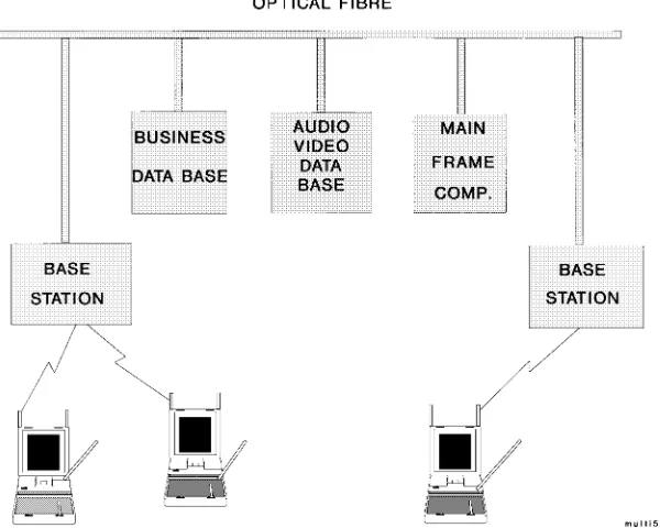
III. WIRELESSMULTIMEDIACOMMUNICATOR
A possible manifestation of the multimedia PS is por-trayed in Fig. 2, which is equipped with a bird’s-eye camera, microphone, and liquid crystal screen, serving as both a video-telephone screen and a computer screen. The conventional keyboard is likely to be replaced by a pressure-sensitive writing tablet, facilitating optical hand-writing recognition [208]–[213], signature verification, etc. The pivotal implementational point of such a multime-dia PS is that of finding the best compromise among a number of contradicting design factors, such as low power consumption, high robustness against transmission errors among various channel conditions, high spectral efficiency, good audio/video quality, low-delay, high-capacity net-working, and so forth. In this paper, we will address a few of these issues in the context of the proposed PS depicted in Fig. 2. The time-variant optimization criteria of a flexible multimedia system can only be met by an adaptive scheme, comprising the firmware of a suite of system components and invoking that combination of speech codecs, video codecs, embedded channel codecs, VAD’s, and modems that fulfills the currently prevalent requirement [68].
These requirements lead to the concept of arbitrarily pro-grammable, flexible, so-called software radios [16], which is virtually synonymous with the so-called tool-box con-cept invoked, for example, in the forthcoming MPEG-4 video codec proposed for wireless video communications [70]. This concept appears attractive also for UMTS-type transceivers. A few examples of such optimization criteria are maximizing the teletraffic carried or the robustness against channel errors, while in other cases, minimization of the bandwidth occupancy, the blocking probability, or the power consumption is of prime concern.
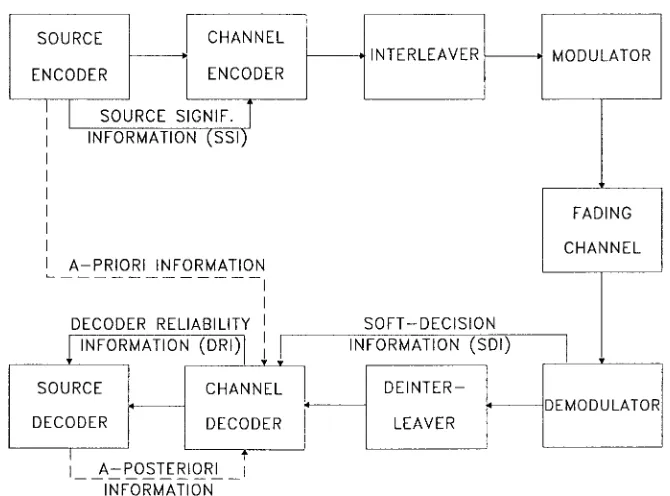
The corresponding network architecture is shown in Fig. 3. The multimedia PS’s communicate with the
so-called BS’s in their vicinity, which are interconnected either directly using optical fiber or in more complex systems via MSC’s. The PS’s can access through the BS a range of services, including business data bases, multimedia data bases, mainframe computers, etc. Let us now turn our attention to some of the information theoretical aspects of wireless communications in order to be able to understand the underlying system’s technical ramifications.
IV. SHANNON’S MESSAGE AND ITSIMPLICATIONS FOR WIRELESS CHANNELS
In mobile multimedia communications, it is always of prime concern to maintain an optimum compromise in terms of the contradictory requirements of low bit rate, high robustness against channel errors, low delay, and low complexity. The minimum bit rate at which the condition of distortionless communications is possible is determined by the entropy of the multimedia source message. Note, however, that in practical terms, the minimum information transmission rate required for the lossless representation of the source signal, which is referred to as the source entropy, is only asymptotically achievable, as the encoding memory length or delay tends to infinity. Any further compression is associated with information loss or coding distortion. Note that the optimum source encoder generates a perfectly uncorrelated source-coded stream, where all the source redundancy has been removed. Therefore, the encoded symbols are independent, and each one has the same significance. Having the same significance implies that the corruption of any of the source-encoded symbols results in identical reconstructed signal distortion over imperfect channels.
Under these conditions, according to Shannon’s funda-mental work [72], [73], [75], the best protection against transmission errors is achieved, if source and channel coding are treated as separate entities. When using a block code of length channel coded symbols in order to encode source symbols with a coding rate of , the symbol error rate can be rendered arbitrarily low if tends to infinity and the coding rate to zero. This condition also implies an infinite coding delay. Based on the above considerations and on the assumption of AWGN channels, source and channel coding have historically been separately optimized.
Fig. 3. Wireless multimedia network.
channels, many of the above-mentioned, asymptotically valid ramifications of Shannon’s theorem have a limited applicability.
A range of practical limitations must be observed when designing wireless multimedia links. Although it is often possible to reduce the required bit rate of state-of-the-art multimedia source codecs while maintaining a certain reconstructed signal quality, in practical terms, this is only possible at a concomitant increase of the implementational complexity and encoding delay. A good example of these limitations is the half-rate GSM speech codec, which was required to approximately halve the encoding rate of the 13 kbits/s full-rate codec, while maintaining less than quadrupled complexity, similar robustness against channel errors, and less than doubled encoding delay. Naturally, the increased algorithmic complexity is typically associated with higher power consumption, while the reduced number of bits used to represent a certain speech segment intu-itively implies that each bit will have an increased relative significance. Accordingly, their corruption may inflict in-creasingly objectionable speech degradations unless special attention is devoted to this problem. It is worth noting that despite its quadruple complexity, the half-rate GSM speech codec maintains a lower power consumption due to low-power 3-V technology than the first launched full-rate codec had.
In a somewhat simplistic approach, one could argue that due to the reduced source rate, we could accommodate an increased number of parity symbols using a more powerful, implementationally more complex, and lower rate channel codec while maintaining the same transmission bandwidth. However, the complexity, quality, and robustness tradeoff of such a scheme would not be very attractive.
A more intelligent approach will be required in order to design better wireless multimedia transceivers [73], [74] for
bursty mobile radio channels. The simplified schematic of such an intelligent transceiver is portrayed in Fig. 4. Perfect source encoders operating close to the information theoreti-cal limits of Shannon’s predictions can only be designed for stationary source signals, a condition not satisfied by most multimedia source signals. Further previously mentioned limitations are the encoding complexity and delay. As a consequence of these limitations, the source-coded stream will inherently contain residual redundancy, and the corre-lated source symbols will exhibit unequal error sensitivity, requiring unequal error protection. Following Hagenauer [73], [74], we will refer to the additional knowledge as regards the different importance or vulnerability of various source-coded bits as SSI, whereas we will refer to the confidence associated with the channel decoder’s decisions as DRI.
Fig. 4. Intelligent transceiver schematic.
such as the American IS-95 system [43]. Video codecs, such as the variable-rate MPEG-1 [80] and MPEG-2 [81] codecs, even more explicitly rely on the fluctuation of the source statistics. For example, when a new object is introduced in the scope of the camera, which cannot be predicted on the basis of already known previous video frames, then the bit rate is typically increased.
The role of the interleaver and deinterleaver [79] seen in Fig. 4 is to rearrange the channel coded bits before transmission. The mobile radio channel typically inflicts bursts of errors during deep channel fades, which often overload the channel decoder’s error-correction capability in certain source-signal segments while other segments are not benefiting from the channel codec at all, since they may have been transmitted between fades and hence are error free even without channel coding. This problem can be circumvented by dispersing the bursts of errors more randomly between fades so that the channel codec is faced always with an “average-quality” channel rather than the bimodal faded/nonfaded condition, although only at the cost of increased system delay, which may become an impediment in interactive multimedia communications. In other words, channel codecs are most efficient if the chan-nel errors are near uniformly dispersed over consecutive received segments.
In its simplest manifestation, an interleaver is a memory matrix that is filled with channel coded symbols on a row-by-row basis, which are then passed on to the modulator on a column-by-column basis. If the transmitted sequence is corrupted by a burst of errors, the deinterleaver maps the received symbols back to their original positions, thereby dispersing the bursty channel errors. An infinite-memory channel interleaver is required in order to perfectly ran-domize the bursty errors and therefore to transform the Rayleigh-fading channel’s error statistics into that of an
AWGN channel, for which Shannon’s information theo-retical predictions apply. Since in interactive multimedia communications the tolerable delay is strictly limited, the interleaver’s memory length and efficiency are also limited. For further details on the effects of various interleavers on the error-correction codec’s efficiency, the interested reader is referred to [79].
A specific deficiency of the above-mentioned rectangular interleavers is that in case of a constant vehicular speed, the Rayleigh-fading mobile channel typically produces periodic fades [216], [217] and error bursts at travelled distances of , where is the carrier’s wavelength, which may be mapped by the rectangular interleaver into another set of periodic bursts of errors. Again, a range of more random rearrangement or interleaving algorithms exhibiting a higher performance than rectangular interleavers has been proposed for mobile channels in [79], where also a variety of practical channel coding schemes have been portrayed. Section V gives a brief overview of the recent activities in speech source coding, Section VI provides a rudimentary introduction to video source coding, while Section VII highlights the principles of graphical source coding. For a full review of speech source coding schemes for mobile systems, the interested reader is referred to [84]–[91]. Joint source and channel coding was the subject of [92], whereas modulation and transmission arrangements for wireless channels have been studied in [4], [6], [9], [68], and [69].
is then often used by the channel decoder in order to invoke MLSE based on the Viterbi algorithm [79], [311] in order to improve the system’s performance with respect to conventional hard-decision decoding. Following the above rudimentary review of Shannon’s information theory, the rest of this paper is devoted to practical issues of wire-less multimedia communications. Let us initially consider briefly the recent advances in speech source coding.
V. SPEECH SOURCECODING
A. A Historical Perspective on Speech Codecs
Following the 64 kbits/s PCM and 32 kbits/s ADPCM G.721 recommendations standardized by the ITU, in 1986, the 13 kbits/s RPE [105], [106] codec was selected for the pan-European mobile system known as GSM. More recently, VSELP [107], [108] codecs operating at 8 and 6.7 kbits/s were favored in the American IS-54 and Japanese PDC wireless networks. These developments were followed by the 4.8 kbits/s DoD codec [112]. The state of the art was documented in a range of excellent monographs by O’Shaughnessy [87], Furui [88], Anderson and Se-shadri [92], Kondoz [89], and Kleijn and Paliwal [90], and in a tutorial review by Gersho [78]. More recently, the 5.6 kbits/s half-rate GSM quadruple-mode VSELP speech codec standard developed by Gerson et al. [109] was approved, while in Japan, the 3.45 kbits/s half-rate PDC speech codec invented by Ohya et al. [113] using the PSI CELP principle was standardized. Other currently investigated schemes are the PWI proposed by Kleijn [114], MBE suggested by Griffin et al. [115], and IZFPE codecs advocated by Hiotakakos and Xydeas [116]. In the low-delay but more error sensitive backward adaptive class, the 16 kbits/s ITU G.728 codec [117] developed by Chen et al. from the AT&T speech team hallmarks a significant step. This was followed by the equally significant development of the more robust, forward-adaptive, 15–ms-delay G.729 algebraic (A)CELP arrangement proposed by the University of Sherbrooke team [122], [123], AT&T, and NTT [118]. Last, the standardization of the 2.4 kbits/s DoD codec led to intensive research in this very low rate range, and the MELP codec by Texas Instruments was identified [119] in 1996 as the best overall candidate scheme.
Before concluding our discourse on speech codecs, let us briefly highlight the problems associated with 7-kHz-bandwidth commentatory quality speech coding.
B. Wide-Band Speech Codecs
For the sake of completeness, we note briefly that 7-kHz-bandwidth speech codecs offer more transparent speech quality than their narrow-band counterparts at typically higher bit rate and algorithmic complexity.
One of the problems associated with full-band coding of wide-band speech is the codec’s inability to treat the less predictable high-frequency, low-energy speech band, which was tackled by the ITU G.722 codec using split-band or subsplit-band coding. Although the upper subsplit-band is
important for maintaining an improved intelligibility and naturalness, it only contains a small fraction of the speech energy, which is on the order of 1%, and therefore its bit-rate contribution has to be limited appropriately. The ITU G.722 codec [131] uses two equal-width subbands, whose signals are encoded employing ADPCM techniques. It has the ability of transmitting speech at 64, 56, or 48 kbits/s, while allocating 0, 8, or 16 kbits/s capacity for data transmission.
Quackenbush [132] suggested a transform-coded ap-proach in order to allow for a higher flexibility in terms of allocating the bits available, which was proposed originally by Johnston [133] for 30-kHz-sampled high-fidelity audio signals, and reduced the bit rate required according to the lower sampling rate of 16 kHz. Ordentlich and Shoham proposed a low-delay CELP-based 32 kbits/s wide-band codec [134], which achieved a similar speech quality to the G.722 64 kbits/s codec at a concomitant higher complexity. The backward-adaptive linear predictive coding (LPC) filter used had an order of 32, which was significantly lower than the filter order of 50 used in the G.728 codec [117]. The G.728 filter order of 50 was able to cater for long-term periodicities of up to 6.25 ms, corresponding to pitch frequencies down to 160 Hz at a sampling rate of 8 kHz without a long-term predictor (LTP), allowing better reconstruction for female speakers. The filter order of 32 at a sampling frequency of 16 kHz cannot cater for long-term periodicities. Nonetheless, the authors opted for using no LTP. In contrast to the G.728 codebook of 128 entries, here 1024 entries were used to model the five-sample excitations.
In a contribution by Black et al. [135], the backward-adaptive principle was retained for the sake of low delay, but it was combined with a split-band approach. The low-band was encoded by a backward-adaptive CELP codec using a tenth-order LPC filter updated over 148-kHz-sampled samples or 1.75 ms. The authors argued that it was necessary to incorporate a forward-adaptive LTP in order to counteract the potentially damaging error feedback effect of the backward-adaptive LPC analysis. The upper band typically contains a less structured, noise-like signal, which has a slowly varying dynamic range. Black et al. here proposed to use a sixth order forward-adaptive predictor updated over a 56-sample interval, which is quadrupled in comparison to the low band. Backward-adaptive prediction would be unsuitable for this less accurately quantized band, which would precipitate the effect of quantization errors in future segments.
ITU G.729 8-kbits/s low-delay codec using a 15-bit ACELP codebook and five encapsulated loops [121], [122].
Here, we conclude our discussion of speech source codecs and briefly classify a range of video codecs suitable for wireless videophony and other wireless visual communications services before focusing our attention on wireless transmission aspects.
VI. VIDEO SOURCECODING
A. Motivation and Background
Motivated by the proliferation of wireless multimedia services [139], [140], a plethora of video codec schemes have been proposed for various applications [141]–[156], but perhaps the most significant advances in the field are hallmarked by the MPEG-4 initiative [70]. The design of video-phone schemes centers around the best compromise among a number of inherently contradictory specifications, such as video quality, bit rate, implementational complex-ity, robustness against channel errors, coding delay, bit-rate fluctuation, and the associated buffer-length requirement. Many of these aspects have been treated in a number of es-tablished monographs by Netravali and Haskell [143], Jain [191], and Jayant and Noll [85], as well as Gersho and Gray [149]. A plethora of video codecs have been proposed in the excellent special issues edited by Tzou et al. [157], Hubing [158], and Girod et al. [159] for a range of bit rates and applications, but the individual contributions by a number of renowned authors are too numerous to review. Khansari et al. [166] as well as Pelz [180] reported promising results on adopting the H.261 codec for wireless applications by invoking powerful signal-processing and error-control techniques in order to remedy the inherent source-coding problems due to stretching its application domain to hostile wireless environments. F¨arber et al. [167]–[170] also con-tributed substantially toward advancing the state of the art in the context of the H.263 codec as well as in motion compensation [168], [169], as did Eryurtlu, Sadka, and Kondoz [174]–[175]. Further important contributions in the field were due to Chen et al. [181], Illgner and Lappe [182], Zhang [183], Ibaraki et al. [184], Watanabe et al. [185], the MPEG-4 consortium’s endeavors [71], and the efforts of the Mobile Audio-Video Terminal Consortium. VQ-based schemes were advocated by Ramamurthy and Gersho [149], as well as by Torres and Huguet [150]. A major feature topic of the European Community’s Fourth Framework Program [44], [45] on ACTS is video communications over a range of wireless and fixed links.
[image:9.612.308.546.52.245.2]In this section, initially we focused our attention on the design and performance evaluation of wireless video telephone systems suitable for the robust transmission of QCIF sequences over conventional mobile radio links, such as the pan-European GSM system [40], the American IS-54 [41] and IS-95 [43] systems, and the Japanese PDC system [42]. In contrast to existing standard codecs, such as the ITU H.261 scheme and the MPEG-1 [80], MPEG-2 [81], and MPEG4 [70] arrangements, our proposed video codec’s
Fig. 5. Simplified schematic of motion compensation [186].
fixed but arbitrarily programmable bit rate facilitates its employment also in future intelligent systems, which are likely to vary their bit rate in response to various propaga-tion and teletraffic condipropaga-tions. We will conclude the secpropaga-tion with a brief overview of the ITU H.263 standard video codec, which is a flexible scheme suitable for a range of multimedia visual applications at various bit rates and video resolutions.
B. Motion Compensation
The ultimate goal of low-rate image coding is to remove redundancy in both spatial and temporal domains and thereby reduce the required transmission bit rate. The temporal correlation between successive image frames is typically removed using block-based motion compensation, where each block to be encoded is assumed to be a motion-translated version of the previous locally decoded frame.
The vector of motion translation or MV is typically found with the help of correlation techniques, as seen in Fig. 5. Specifically, a legitimate motion-translation region or search scope is stipulated within the previous locally decoded frame, the block to be encoded is slid over this region according to a certain algorithm, and the location of highest correlation is deemed to be the destination of the motion translation. Motion compensation (MC) is then car-ried out by subtracting the appropriately motion-translated previous decoded block from the one to be encoded in order to generate the MCER. Clearly, the image is decomposed in motion translation and MCER, and both components have to be encoded and transmitted to the decoder for image reconstruction. The motion compensation removes some of the temporal redundancy, and the variance of the MCER becomes much lower than that of the original image, which ensures bit-rate economy.
Fig. 6. Simple video codec schematic.
of these techniques will be highlighted in the forthcoming subsections.
When a low codec complexity and low bit rate are re-quired, the motion-compensation technique described above can be replaced by simple frame differencing. In frame differencing, the whole of the previous locally decoded image frame is subtracted from the one to be encoded without the need for the above correlation-based motion prediction, which may become very computationally in-tensive for high-resolution, high-quality video portraying high-dynamic scenes. Such a simple video codec schematic based on simple frame differencing is shown in Fig. 6. Although the MCER residual variance remains somewhat higher for frame differencing than in case of full motion compensation, there is no pattern-matching search, which reduces the complexity, and no MV’s have to be encoded, which may reduce the overall bit rate. Observe in Fig. 6 that after frame differencing, the encoded MCER is conveyed to the transceiver and also locally decoded. This is necessary to be able to generate the locally reconstructed video signal, which is invoked by the encoder in subsequent MC steps. The encoder uses the locally reconstructed rather than the original input video frames, since these are not available at the decoder, which would result in misalignment between the encoder and decoder. This local reconstruction operation is carried out by the adder in the figure, superimposing the decoded MCER on the previous locally decoded video frame. The operations are similar if full MC is used. Practical codecs such as, for example, the ITU H.263 scheme, often combine the inter- and intraframe coding techniques on a block-by-block basis, where MC is employed only if it is deemed advantageous in MCER reduction terms.
In the case of highly correlated consecutive video frames, the MCER typically exhibits “line-drawing” characteristics, where large sections of the frame difference signal are “flat,” characterized by low pixel magnitude values, while the motion contours, where the frame differencing has failed to predict the current pixels on the basis of the previous locally decoded frame, are represented by larger values, as seen in at the center of Fig. 9. Consequently,
efficient MCER residual coding algorithms must be able to represent such textured MCER patterns adequately, a topic to be addressed in the forthcoming subsections. Let us initially consider a bandwidth-efficient cost-gain quantized DCT-based codec [188].
C. DCT-Based Video Codec
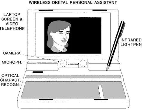
Our DCT-based video codec’s outline is depicted in Fig. 7. The DCT [191] has been popular in video-compression standards [80], [81] since it exhibits a so-called energy compaction property, implying that upon transforming a correlated or predictable signal to the spatial frequency domain, most of its energy will be compacted to a few high-energy, low-frequency coefficients. This is a consequence of the Wiener–Khnitsin theorem, stating that the power spectral density (PSD) and the autocorrelation function (ACF) are Fourier transform pairs. Hence, the flat ACF of a predictable, slowly varying signal implies a compact low-pass-type PSD, which is amenable to compression since in the spatial frequency domain, a lower number of coefficients has to be transmitted than in the temporal domain. It is important to note that the MC often removes most of the redundancy from the correlated temporal-domain video frame, and hence the DCT of the MCER may even result in an expanded spatial frequency-domain representation, which can be counteracted, for example, by adaptive bit-allocation schemes. Strobach [147] proposed QT coding in order to encode the MCER and mitigate this problem. Alternative frequency-domain solutions include SBC [144], [145] or wavelet coding [146], which facilitate a flexible control over the allocation of bits in the spatial frequency domain. The MPEG standard codecs [80], [81] and the H.261 and H.263 codecs scan and entropy code the DCT coefficients and also allow direct encoding of the more correlated video signal on a block-by-block basis. VQ [149]–[151] can be carried out in both the frequency and time domains, but a persistent deficiency is their difficulty to handle sharp edges adequately.
Returning to the DCT principle, our proposed DCT-based codec was designed to achieve a time-invariant compression ratio associated with a fixed but programmable encoded video rate of 5–13 kbits/s.1The codec’s operation is initialized in the intraframe mode, but once it switches to the interframe mode, any further mode switches are optional and only required if a drastic scene change occurs.
In the intraframe mode, the encoder transmits the coarsely quantized block averages for the current frame, which provides a low-resolution initial frame required for the operation of the interframe codec both at the commence-ment and during later stages of communications in order to prevent encoder/decoder misalignment. For 176 144-pixel ITU standard QCIF images in a specific scenario [188], we limited the number of video-encoding bits per frame to 1136, corresponding to a bit rate of 11.36 kbits/s at 10 frames/s.
Fig. 7. DCT-codec schematic [188].
In the motion compensation, 8 8 blocks are used. At the commencement of the encoding procedure, the MC scheme determines an MV for each of the 8 8 blocks using full search. The MC search window is fixed to 4 4 pels around the center of each block, and hence a total of 4 bits are required for the encoding of 16 possible positions for each MV. Before the actual motion compensation takes place, the codec tentatively determines the potential benefit of the compensation in terms of motion-compensated error energy reduction. Then the codec selects as “motion active” those blocks whose gain exceeds a certain threshold. This method of classifying the blocks as motion active and motion passive results in an active/passive table, which consists of a 1-bit flag for each block, marking it as passive or active.
Pursuing a similar approach, gain control is also applied to the DCT-based compression. Every block is DCT trans-formed and quantized. To take account of the nonstationary nature of the MCER and its time-variant frequency-domain distribution, four different sets of DCT quantizers were designed. The quantization distortion associated with each quantizer is computed in order to be able to choose the best one. Ten bits are allocated for each quantizer, each of which is a trained Max–Lloyd quantizer catering for a spe-cific frequency-domain energy distribution class. All DCT blocks whose coding gain exceeds a certain threshold are marked as DCT-active, resulting in a similar active/passive table as for the motion vectors. For this second table, we
apply the same run-length compression technique as above. Again, if the number of bits required for the encoding of the DCT-active blocks exceeds half of the maximum allowable number, blocks around the fringes of the image, rather than those in the central eye and lip sections, are considered DCT-passive. If, however, the active DCT coefficient and activity table do not fill up the fixed-length transmission burst, the thresholds for active DCT blocks are lowered and all tables are recomputed.
The bit-allocation scheme was designed to deliver 1136 bits per frame, which is summarized in Table 1. The encoded bitstream begins with a 22-bit frame alignment word (FAW). This is necessary to assist the video decoder’s operation in order to resume synchronous operation after loss of frame synchronization over hostile fading channels. The partial intraframe update refreshes only 22 out of 396 blocks every frame. Therefore, every 18 frames, or 1.8 seconds, the update refreshes the same blocks. This periodicity is signalled to the decoder by transmitting the inverted FAW. An MV is stored using 13 bits, where 9 bits are required to identify one of the 396 block indexes using the enumerative method and 4 bits for encoding the 16 possible combinations of the and displacements. The 8 8 DCT-compressed blocks use a total of 21 bits, again 9 for the block index, 10 for the DCT coefficient quantizers, and 2 bits to indicate which of the four quantizers has been applied. The total number of bits becomes
Table 1 Bit-Allocation Table Per QCIF Video Frame for the Fixed-Rate DCT Codec [188]
Fig. 8. PSNR versus frame index performance at various bit rates for the “Miss America” sequence [188].
added in order to obtain a total of 1136 bits suitable in terms of bit packing requirements for the specific forward error-correction block codec used.
The encoded parameters are transmitted to the decoder and also locally decoded in order to be used in future motion predictions. The video codec’s peak (P)SNR versus frame index performance is shown in Fig. 8, where the PSNR is defined as the conventional SNR except that instead of the actual video signal power, a video pixel value of 255 is assumed, yielding a pixel power of 255 for all pixel positions across the video frame. Since 255 is the highest possible value for an 8-bit pixel representation, the PSNR is typically higher than the conventional SNR. The codec proposed was subjected to bit-sensitivity analysis, and a QAM-based [68] source-sensitivity matched transceiver was designed in order to transmit the video stream over wireless channels. The interested reader is referred to [188] for further details. Having described the principles of DCT-based video coding, let us now consider QT coding of the MCER [189].
D. QT Structured Coding
The proposed QT codec shares the structure of the previ-ous DCT-based scheme portrayed in Fig. 7 but employs QT coding of the MCER. QT’s represent a subclass of the so-called region growing techniques, where the image, in our case the MCER generated by the MC scheme, is described with the help of variable-size sectors characterized by similar features, in this case, similar gray levels. Explicitly,
the MCER is described in terms of two sets of parameters: the structure of similar regions and their gray levels. Note that the information characteristic of the QT structure is potentially much more sensitive to bit errors than the gray-level coding bits.
Before QT decomposition takes place, the frame differ-ence signal is divided in 16 16-pixel blocks perfectly tiling the original difference frame. Creating the QT regions is a recursive operation. Considering each individual pixel, two or more neighbors are merged together if a certain merging criterion is satisfied. This criterion may be, for instance, a similar gray level. This merging procedure is repeated until no more regions satisfy the merging criterion; hence, no more merging is possible. Similarly, the QT regions can be obtained in a top-down approach, dividing the MCER in a number of sections, if the sections do not satisfy the similarity criterion and continue until the pixel level is reached and no further splits are possible.
The QT approach is one possible implementation of the region growing techniques. This process can be observed in Fig. 9. For a rectangular region, an algorithmically attractive implementation is: when commencing at the pixel level, four quadrants of a square are merged together if the matching criterion is met. The gray levels of the quadrants of a square are represented by , and their mean
is computed according to . If
Fig. 9. QT segmentation example with and without overlaid MCER and original video frame [189].
criterion can be formulated as follows:
True (1)
where represents the logical ANDoperation.
It is expected that if the system parameter is reduced, the matching criterion becomes more stringent and hence less merging takes place, which is likely to increase the required encoding rate at a concomitantly improvement of the MCER’s representation quality. In contrast, an increased value is expected to allow more merging to take place and hence reduce the bit rate, as we will show in our results section.
If the merging criterion is satisfied, the mean gray level becomes the gray level of the merged quadrant in the next generation, and so on. At this stage, it is important to note that the quality-control threshold does not need to be known to the QT decoder. Therefore, the image representation quality can be rendered position dependent within the frame being processed, which allows weighting to be applied to important image sections such as the eyes and lips without increasing the complexity of the decoder or the transmission rate.
Pursuing the top-down QT decomposition approach, the frame difference signal constitutes a so-called node in the QT. After splitting, this node gives rise to four further nodes, which are classified on the basis of the “similarity criterion.” Specifically, if all the pixels at this level of the QT differ from the mean by less than the threshold , then they are considered to be a “leaf node” in the QT. Hence, they do not have to be subjected to further “similarity tests”; they can be represented simply by the mean value .
If, however, the pixels constituting the current node to be classified differ by more than the threshold , the pixels forming the node cannot be adequately represented by their mean , and thus they must be further split until the threshold condition is met. This repetitive splitting process is continued until there are no more nodes to split, since all the leaf nodes satisfy the threshold criterion, as shown in Fig. 9. Consequently, the QT structure describes the contours of similar gray levels in the frame difference signal.
To be able to reproduce the encoded image, not only the gray levels of the leaf nodes but also the QT structure
must be efficiently encoded and communicated to the decoder. Fortunately, the QT structure can be efficiently described with the help of a variable-length code. At the commencement of image communications, a low-resolution version of the first image frame is encoded and transmitted to the decoder in order to assist in its operation. Then the MCER signal is computed, which is subjected QT coding, before transmission to the decoder. Again, the schematic of the QT codec obeys the structure of Fig. 6. The QT-coded MCER is locally decoded and added to the previous locally decoded frame and stored in the frame buffer for the duration of one frame in order to generate the next block estimates for the MC operation. A range of techniques related to the optimum QT splitting and bit-allocation techniques were suggested in [189], where also details of the source-matched video transceiver can be found. Adequate video quality was achieved for the Miss America sequence for a bit rate of 11.36 kbits/s when using scanned QCIF images of 10 frames/s.
Without aiming for an in-depth treatment, we briefly allude to the concept of vector quantized video codecs, where the MCER of an 8 8 pixel block is represented by the best matching entry of the two-dimensional codebook shown in Fig. 10. This principle also allowed us to contrive an 11.36-kbits/s QCIF codec for wireless video telephony, the details of which were presented in [187], where the full transceiver performance over fading channels is also characterized. The above-mentioned range of fixed-rate video codecs is compared in terms of error resilience and video quality in [190]. In [187]–[189], a range of flexible reconfigurable multilevel transceivers were designed for the transmission of the VQ-, DCT-, and QT-coded video streams by allocating an addition physical speech channel for video telephony. For reasons of space economy, how-ever, these results were not included here. Similar video PSNR versus channel SNR results are provided here using the ITU H.263 video codec and a reconfigurable transceiver in order to characterize the expected video performance in Figs. 27 and 28.2
In closing, we note again that the literature of video com-pression is very rich [139]–[156], and recent developments led to the definition of the MPEG-1, MPEG-2, H.261, and H.263 standards. Although these codecs rely on vulnerable
Fig. 10. Enhanced sample codebook with 128 82 8 vectors [190].
variable-length coding techniques, work is also under way toward contriving more robust coding algorithms, such as those to be incorporated in the forthcoming MPEG-4 scheme [71], [70]. In the next subsection, we briefly highlight the features of the standard H.263 scheme, which is an error-sensitive, variable-rate scheme but achieves a very high compression ratio. Hence, to date, it is the best existing standardized video codec. We will also propose appropriate transmission techniques to support its operation in a wireless video-phone scheme.
E. The H.263 ITU Codec
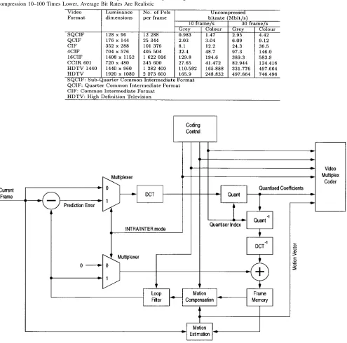
The H.263 codec was detailed in [193] and [194], while a number of transmission schemes designed for accommo-dating its rather error-sensitive bit stream were proposed in [167], [170], [179]. As an illustrative example, in Table 2, we summarize the various video resolutions supported by the H.261 and H.263 ITU codecs in order to demonstrate their flexibility [192]. Their uncompressed bit rates at frame scanning rates of both 10 and 30 frames/s for both gray
and color video are also listed. The mature H.261 standard defined two different picture resolutions, namely, QCIF and CIF, while the H.263 codec has the ability to support five different resolutions. All H.263 decoders must be able to operate in sun (S)QCIF and QCIF modes and optionally support CIF, 4 CIF, and 16 CIF formats.
Table 2 Various Video Formats and Their Uncompressed Bit Rate. Upon Using Compression 10–100 Times Lower, Average Bit Rates Are Realistic
Fig. 11. Simplified H.261/H.263 schematic [192].
partly explained by the extensive employment of entropy coding schemes. The performance of a complete adaptive video-phone system will be portrayed after considering the associated wireless transmission aspects.
Here, we curtail our discussion on video codecs and provide some notes on another aspect of multimedia com-munications, namely, graphical correspondence.
VII. GRAPHICAL SOURCECODING
A. Background
Telewriting is a multimedia telecommunications service enabling the bandwidth-efficient transmission of handwrit-ten text and line graphics through fixed and wireless
com-munication networks [196]–[201]. Differential chain coding has been successfully used for graphical communications over e-mail networks [196] or teletext systems [199], where bit-rate economy is achieved by exploiting the correlation between successive vectors. References [197] and [202] address some of the associated communications aspects. A plethora of further excellent papers were contributed to the literature of chain coding by Prasad and his colleagues from Delft University [203]–[205].
B. Fixed-Length Differential Chain Coding [206]
Fig. 12. Image quality (PSNR) versus coded bit rate for H.263 Miss America simulations at 10 and 30 frames/s using SQCIF, QCIF, and CIF sequences [192].
of the legitimate motion vectors, in steps represented by the vectors portrayed in Fig. 13. The bold dots in the figure represent the next legitimate pixels during the graphical trace’s evolution. In principle, the graphical trace can evolve to any of the surrounding eight pixels, and hence a 3-bit code word is required for lossless coding. DCC [203] exploits that the most likely direction of stylus movement is a straight extension, corresponding to vector zero, and with a gradually reducing probability of sharp turns, corre-sponding vectors having higher indexes. Explicitly, we have found that while vector zero typically has a probability of around 0.5 for a range of graphical source signals, including English and Chinese handwriting, a map, and a technical drawing, the relative frequency of vectors 1 is around 0.2, while vectors 2, 3 have probabilities around 0.05. This suggests that the coding efficiency can be improved using the principle of entropy coding by allocating shorter code words to more likely transitions and longer ones to less likely transitions.
[image:16.612.271.540.62.566.2] [image:16.612.309.537.371.560.2]In [206], we embarked on exploring the potential of a graphical coding scheme dispensing with variable-length coding, which we refer to as FL-DCC. FL-DCC was con-trived in order to comply with the time-variant-resolution and/or bit-rate constraints of intelligent adaptive multimode terminals, which can be reconfigured under network control to satisfy the momentarily prevailing teletraffic, robustness, quality, etc. system requirements. To maintain lossless graphics quality under lightly loaded traffic conditions, the FL-DCC codec can operate at a rate of bits/vector, although it has a higher bit rate than DCC. However, since in voice and video coding typically perceptually unimpaired
Fig. 13. Coding ring.
lossy quantization is used, we embarked on exploring the potential of the reconfigurable FL-DCC codec under low-rate, lossy conditions.
Fig. 14. FL-DCC coding syntax [206].
associated subjective coding impairment is minor. Under degrading channel conditions or higher teletraffic load, the FL-DCC coding rate has to be reduced to in order to be able to invoke a less bandwidth-efficient but more robust modulation scheme or to generate less packets contending for transmission. In this case, only vectors 1 and 1 of Fig. 13 are legitimate. The subjective effects of the associated zigzag trace will be removed by the decoder, which can detect these characteristic patterns and replace them by a fitted straight line.
In general terms, the size of the coding ring is given by
, where is referred to as the order of
the ring and is a scaling parameter characteristic of the pixel separation distance. Hence, the ring shown in Fig. 13 is first order. The number of nodes in the ring is . The data syntax of the FL-DCC scheme is displayed in Fig. 14. The beginning of a trace can be marked by a typically 8-bit-long PD code, while the end of a trace can be marked by a PU code. To ensure that these codes are not emulated by the remaining data, if this would be incurred, bit stuffing must be invoked. We found that in complexity and robustness terms using a VC constituted a more attractive alternative for our system. The starting coordinates , of a trace are directly encoded using, for example, ten and nine bits in case of a video graphics array resolution of 640 480 pixels.
The first vector displacement along the trace is encoded by the best fitting vector defined by the coding ring as the SV. The coding ring is then translated along this starting vector to determine the next vector. A differential approach is used for the encoding of all the following vectors along the trace in that the differences in direction between the present vector and its predecessor are calculated, and these vector differences are mapped into a set of fixed-length
-bit code words, which we refer to as FV’s.
We designed a wireless 4-QAM-based [68] transceiver for the transmission of FL-DCC encoded graphical source signals and evaluated the system’s robustness over Rayleigh-fading channels with second-order switched diversity, using automatic repeat requests limited to a maximum of three transmission attempts (TX3) [207]. Here, we refrain from providing PSNR versus channel SNR curves; for these, the interested user is referred to [207]. However, the corresponding subjective graphical quality and the associated PSNR values are summarized in Fig. 15 for the channel SNR range of 5–12 dB, respectively. Due to its low channel capacity requirement, the FL-DCC coded signal is readily accommodated by the voice signal during passive speech spurts when using a VAD [40]. Last, it is noteworthy that the ITU standardized two different CC schemes in the T.150 recommendation for use over conventional low-BER fixed telephone lines.
For wireless channels, however, the proposed FL-DCC scheme is preferable due to its higher robustness and programmable-rate operation.
We note that an associated multimedia signal manipu-lation relying on writing tablets is the field of handwrit-ing recognition for both on-line and off-line applications [208]–[213]. Many of the techniques used are based on HMM’s, which are widely employed in the field of speech recognition. Previous research has shown that HMM’s are applicable to both off-line [212] and on-line [208], [210], [213] handwriting recognition problems. The advantage of such statistical methods is that they can handle variability in the writing process of an individual but are also capable of identifying and capturing the individual features of the handwritten characters by taking into account dy-namic, pressure-dependent features. In many applications, the handwritten data are described by the directional writing angle as a function of the distance along the writing trajectory.
Following the above brief excursion to graphical source compression and signal processing, here we turn our atten-tion to wireless communicaatten-tions aspects, commencing with a review of the frequency reuse concept of cellular systems.
VIII. CELLUARCOMMUNICATIONSBASICS
A. The Cellular Concept
A common feature of the previously mentioned mobile radio systems is that communications take place between a stationary BS and a number of roaming MS’s or PS’s [1]–[9]. The BS’s and the MS’s transmitter is expected to provide a sufficiently high received signal level for the far-end receivers in order to maintain the required communications integrity. This is usually ensured by power control. The geographical area in which this condition is satisfied is termed a traffic cell, which typically has an irregular shape, depending on the prevailing propaga-tion environment determined by terrain and architectural features as well as the local paraphernalia. In theoretical studies, often a simple hexagonal cell structure is favored for its simplicity, where the BS’s are located at the centers of the cells.
In an ideal situation, the total bandwidth available to a specific mobile radio system could be allocated within each cell, assuming that there is no energy spilt in the adjacent cell’s coverage area. However, since wave propagation cannot be shielded at the cell boundary, PS’s near the cell edge would experience approximately the same signal energy within their channel bandwidth from at least two BS’s. This phenomenon is called cochannel interference. A remedy to this problem is to divide the total bandwidth
in frequency slots of and assign
Fig. 15. Subjective effects of transmission errors for theb = 1 16-QAM, Rayleigh/diversity, TX3 scheme for PSNR values of (left to right, top to bottom) 49.47, 42.57, 37.42, 32.01, 27.58, and 21.74 dB [207].
interference between the black cochannel cells having an identical frequency set is not eliminated, but due the in-creased cochannel BS distance or frequency reuse distance, the interference is significantly reduced. Note also that in analytical and simulation-based interference studies, the “second tier” of interfering cells, which are hatched, is typically neglected.
A consequence of the above cellular concept, however, is that the total number of MS’s that can be supported simultaneously over a unit area is now reduced by a factor of . This is because assuming a simple FDMA scheme, where each MS is assigned an RF carrier and a user
bandwidth of , now only number of
MS’s can be serviced, rather than .
This problem can be circumvented by making the clusters as small as the original cells, which is achieved by reducing the transmitted power. In fact, further reduction of the cell size has the advantage of serving more and more users while requiring a reduced transmitted signal power and hence lightweight batteries. A further favorable effect is that the smaller the traffic cell, the more benign the propagation environment due to the presence of a dominant
LOS propagation path and the mitigated effects of the multipath propagation. These arguments lead to the concept of micro- and picocells [20]–[22], which are often confined to the size of a railway station or airport terminal and an office, respectively. Cluster sizes smaller than are often used in practice in order to enhance the system’s spectral efficiency, but such schemes require modulation arrangements that are resilient against the increased cochan-nel interference. These different cells will have to coexist in practical systems, where, for example, an “oversailing” macrocell can provide an emergency handover capability for the microcells when the MS roams in a propagation blind spot but cannot hand over to another microcell, since in the target microcell no traffic channels are available.
Fig. 16. Hexagonal cells and seven-cell clusters.
Fig. 17. Various traffic cells.
and channel most of the energy in the street canyon, which mitigates the signal’s variability and hence has more benign fading. Furthermore, microcells also reduce the signal’s dis-persion due to path-loss differences. Last, indoors, picocells provide typically even better channels and tend to mitigate cochannel interferences due to partitions and ceilings.
[image:19.612.47.281.421.605.2]The previously mentioned handover process is crucial as regards the perceived GOS, and a wide range of different complexity techniques have been proposed—for example,
Fig. 18. Handover control parameters.
A further important issue associated with the cellular concept and cellular planning is DCA, where a variety of algorithms can be invoked to support the system’s operation [25]–[29] in order to mitigate the effects of CCI and to maximize the number of traffic channels supported. These techniques are typically invoked in cordless tele-phone systems, such as DECT and CT2 [12]. The basic concept of DCA is fairly plausible, since the MS scans the physical channels in order to identify the specific channel exhibiting the lowest signal level before camping on the one that was deemed to inflict the lowest level of cochannel interference. Chuang et al. [25]–[27] documented the performance of a variety of DCA algorithms, arguing that these techniques under certain conditions can converge to a local minimum of the total interference averaged over the network. In closing, we note that there exists a different dynamic channel-allocation philosophy, which was proposed by Bernhardt [28], [29], advocating the employment of the worst possible channel that satisfies a minimum SIR condition. This is equivalent to invoking the worst “just tolerable” physical channel for communications, which intuitively allows a more compact frequency reuse pattern to be employed but naturally requires a robust modulation scheme. The overall benefit is an expected higher number of accommodated users.
The family of DCA algorithms is closely related to a range of multiple access schemes; hence, we consider multiple access next.
B. Multiple Access
The physical channel, which the MS and BS use for their communications, can be manifested by a given frequency slot, assigned to the MS for the entire duration of a call. This was the case in most first-generation FDMA mobile radio systems. In the second-generation systems, such as the pan-European GSM [330], the American IS-54 [41], and the Japanese PDC system [42], TDMA was proposed, assigning the whole bandwidth of a TDMA carrier to an MS for a fraction of the time, i.e., for the duration of a time slot. The American IS-95 CDMA system [43] uses all the system bandwidth all the time for all users, communicating with orthogonal signature codes. However, these systems employ contentionless bandwidth allocation, where the physical channel is not exploited to its full capacity due to being assigned to users also during their passive speech spurts, when they are listening or thinking, etc.
By contrast, statistical multiplexing schemes surrender the physical channel during passive speech spurts, when the channel is not actively used by the MS. This often leads to substantially increased user numbers’ being supported by the system. A range of MAC protocols have been advocated in the literature [218]–[228], most of which were featured in a recent excellent overview by Li and Qiu in [32].
PRMA is a statistical multiplexing method for conveying speech signals via TDMA systems, which was proposed by Goodman [218] and Wei [220]. A range of various PRMA-assisted CT systems were proposed in [229]–[233]. The
operation of PRMA is based on the VAD’s being able reliably to detect inactive speech segments [330]. Inactive users’ TDMA time slots are allocated to other users, who become active. The users, who are just becoming active, have to contend for the available time slots with a certain permission probability , which is an important PRMA parameter to be augmented at a later stage.
Previously colliding users contend for the next available time slot with a less-than-unity permission probability in order to prevent them from consistently colliding in their further attempts to attain reservation. If more than one user is contending for a free slot, neither of them will be granted it. If, however, only one user requires the time slot, he can reserve it for future use until he becomes inactive. Under heavily loaded network conditions, when many users are contending for a reservation, a speech packet might have to contend for a number of consecutive slots. When the contention delay exceeds a latency of about 30 ms, the contending speech packet of typically 20-ms duration must be dropped. The probability of packet dropping must be kept below 1%, a value inflicting minimal degradation in terms of perceived speech quality.
Suffice it to say here that in order to find the optimum permission probability , the number of users supported at less than 1% packet dropping must be determined for various values, and the curve’s maximum has to be identified. The rule of thumb is that when a system can support twice the number of slots in comparison to another, the corresponding value must be halved in order to main-tain the desirable contention rate for each slot. When is high, too vigorous contentions are encouraged, resulting in unacceptably high collision rates. By contrast, too low a value does not exploit the system’s full teletraffic capacity due to a modest statistical multiplexing gain.
The performance potential of PRMA was analyzed using the equilibrium point analysis technique by Nanda et al. [221]. The underlying assumption of the equilibrium point analysis is that the PRMA system can be characterized by a Markov model, and the number of users entering a given Markov state is identical to the number of users leaving it. The above PRMA technique was refined by Dunlop et al. [222], where the authors have restricted contentions to contention minislots, thereby mitigating the effects of packet collisions. This scheme was termed PRMA . PRMA was also suggested by Eastwood et al. [232] for multiplexing multimedia users’ transmission packets for transmission to the BS.
![Fig. 5.Simplified schematic of motion compensation [186].](https://thumb-us.123doks.com/thumbv2/123dok_us/1052038.621194/9.612.308.546.52.245/fig-simplied-schematic-of-motion-compensation.webp)

![Fig. 7.DCT-codec schematic [188].](https://thumb-us.123doks.com/thumbv2/123dok_us/1052038.621194/11.612.127.463.57.383/fig-dct-codec-schematic.webp)
![Table 1Bit-Allocation Table Per QCIF Video Frame for the Fixed-Rate DCT Codec [188]](https://thumb-us.123doks.com/thumbv2/123dok_us/1052038.621194/12.612.124.467.67.345/table-allocation-table-qcif-video-frame-fixed-codec.webp)
![Fig. 9.QT segmentation example with and without overlaid MCER and original video frame [189].](https://thumb-us.123doks.com/thumbv2/123dok_us/1052038.621194/13.612.56.371.53.173/fig-segmentation-example-overlaid-mcer-original-video-frame.webp)
![Fig. 10.Enhanced sample codebook with 128 8 � 8 vectors [190].](https://thumb-us.123doks.com/thumbv2/123dok_us/1052038.621194/14.612.68.524.54.471/fig-enhanced-sample-codebook-vectors.webp)