Abstract—This study investigated the effect of scanning speed and gas flow rate on surface finish produced during the laser metal deposition process of Ti6Al4V, an important aerospace alloy. In this work, Nd-YAG laser was employed with coaxial powder deposition nozzle attached to the end effector of a Kuka robot. The laser power was maintained at 3.0 kW and the powder flow rate at a value 2.88 g/min. The scanning speed was varied between 0.01 and 0.05 m/s and the gas flow rate was varied between 1 and 5 l/min. A total of ten samples were produced and the surface roughness was measured using the average of five measurements from each sample. The microstructure was also studied with optical microscope to relate it to the surface roughness. The results showed that, the average surface finish increased as the scanning speed was increased. Conversely, as the gas flow rate was increased the average surface roughness was reduced. In optimizing the laser metal deposition process, the processing parameters need to be optimized. The results from this study will assist in choosing the right powder flow rate and scanning speed especially in applications such as repair and surface modification.
Keywords— Additive Manufacturing, Laser Metal Deposition (LMD), Process parameter, Scanning speed, Surface finish, Titanium alloy.
I. INTRODUCTION
aser metal deposition (LMD) is an attractive additive \ manufacturing process that has been an interesting research
area because of its importance and its promising features. LMD can be used to fabricate near net shape part directly from the three dimensional computer aided design (CAD) model of the part by adding materials layer by layer [1]. LMD is also capable of repairing parts that were prohibitive or not repairable in the past [2, 3]. The competitive advantage of LMD like any other additive manufacturing technology include the geometrical freedom, reduced product to market time, material flexibility, reduce buy-to-fly ratio and possibility of mass customization [4, 5]. LMD
Manuscript received June 2, 2016; revised August 4, 2016. This work was supported by the University of Johannesburg Research Council and L'Oreal-UNESCO for Women in Science.
*Dr. Rasheedat M. Mahamood is a Postdoctoral fellow in the Department of Mechanical Engineering Science, University of Johannesburg, Auckland Park Campus, Johannesburg, South Africa, 2006. (e-mail: [email protected] )
Prof. Esther T. Akinlabi is a Professor in the Department of Mechanical Engineering Science, University of Johannesburg, Auckland Park Campus, Johannesburg, South Africa, 2006. (Phone: +2711-559-2137; email: [email protected]).
can be used to produce functionally graded materials and can be used to process difficult to machine materials like titanium and its alloys [6, 7].
Ti6Al4V is the most widely used titanium alloy because of its excellent properties such as high strength to weight ratio, excellent corrosion resistance properties and it is heat treatable [8, 9]. In spite of the excellent properties if titanium and its alloys, they are classified as difficult to machine materials [7] and processing such materials using the conventional manufacturing processes involve a high cost and time consuming. LMD, an Additive manufacturing technology is an ideal alternative manufacturing process that is does not come in contact with the work material and it offset the problem faced in the traditional manufacturing process. It can also to repair existing worn out part and can be used to produce parts that is made of functionally graded materials [2, 10].
LMD process is a highly non-linear process and sensitive to the processing parameters. Resulting properties are dependent on the processing parameters employed. A number of research studies have been conducted the influence of processing parameters on the properties of laser metal deposited Ti6Al4V [11-15]. In this study, the influence of scanning speed and gas flow rate on the surface roughness of laser metal deposition of Ti6Al4V is investigated. The aim of this study is to help in establishing the optimum process parameter-scanning speed and gas flow rate on the resulting surface roughness which is important to reduce the need of secondary finishing operation which will add to the cost of manufacturing.
II. EXPERIMENTALPROCEDURE
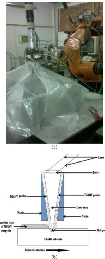
The Ti6Al4V powder that was used in this study is 99.6% pure and of particle size range between 150 and 250 µm. The Ti6Al4V substrate is a square sheet of 72 x 72 x 5 mm dimension and also of 99.6% pure. Before the deposition process, the substrate was sandblasted and washed with acetone to prepare the surface to aid the laser energy absorption. Nd-YAG laser was used for the LMD process which was attached with the coaxial powder nozzle onto the end effector of a Kuka robot. The experimental set-up is available at the CSIR, National Laser Center Pretoria, South Africa. The set-up consists of an improvised glove box to prevent environmental contamination of the deposited part by atmospheric oxygen and Nitrogen. The experimental set-up is shown in Figure 1a and the schematic diagram of the LMD process is shown in Figure 1b.
The laser metal deposition process uses the laser beam to create a melt-pool on the surface of the substrate and then deliver the powder material into the melt-pool. When the melt-pool solidifies, a solid track of the deposited sample is
Effect of Scanning Speed and Gas Flow Rate on
Surface Roughness of LMD Titanium-alloy
Rasheedat M. Mahamood* and Esther T. Akinlabi
produced. The laser power used in this study was fixed at 3.0 kW and powder flow rate at 2.88 g/min. The scanning speed was varied between 0.01 and 0.05 m/s while the gas flow rate was varied between 1 and 5 l/min. The processing parameters are presented in Table 1 and Table. The laser beam was kept at a focal length of 195 mm above the substrate to keep the laser beam at a constant diameter of 2 mm through the experiments.
(a)
(b)
Figure 1 (a) Pictorial diagram of the experimental set-up (b) Schematic diagram of the LMD process (adapted from Mahamoodm et al. [16]
A total of ten samples were produced according to the processing parameters in Tables 1 and 2. After the deposition experiments, the samples were washed with acetone to remove any unmelted powders that sticks on the surface of the samples. The surface roughness of the deposited tracks was measured with the stylus surface analyzer by Jenoptik which was equipped with Hommelmap 6.2 software. The measuring condition used was according
to the ‘BS EN ISO 4288:1998’ standard [17 with the effective measuring length of 4.8 mm; the cut-off length of 0.8 mm; and the measuring range of 400 µm with a sliding speed of 0.50 mm/s. Five measurements were taken on each of the deposited samples, and the arithmetic average of the two dimensional (2D) roughness profiles (Ra) was recorded. After the surface roughness has been measured, the samples are cut in transverse direction to reveal the cross section of the samples. The cut samples were mounted ground and polished following the standard metallurgical preparation of titanium and its alloys [18]. The samples were then etched using the Kroll’s reagent. The microstructures of the samples were studied under optical microscopy (OP) by Olympus BX51M and Tescan, Scanning Electron Microscopy (SEM) equipped with Oxford Energy Dispersion Spectrometry (EDS).
Table 1. Process Parameters with varying scanning speed Sample Label Scanning Speed (m/s)
A1 0.01
A2 9.02
A3 0.03
A4 0.04
A5 0.05
Table 2 Process Parameters with varying gas flow rate Sample Label Gas Flow Rate (l/min)
B1 1
B2 2
B3 3
B4 4
B5 5
III. RESULTS AND DISCUSSION
[image:2.595.71.273.151.646.2]enhance the formation of martensitic microstructure which is hard and brittle.
(a)
(b)
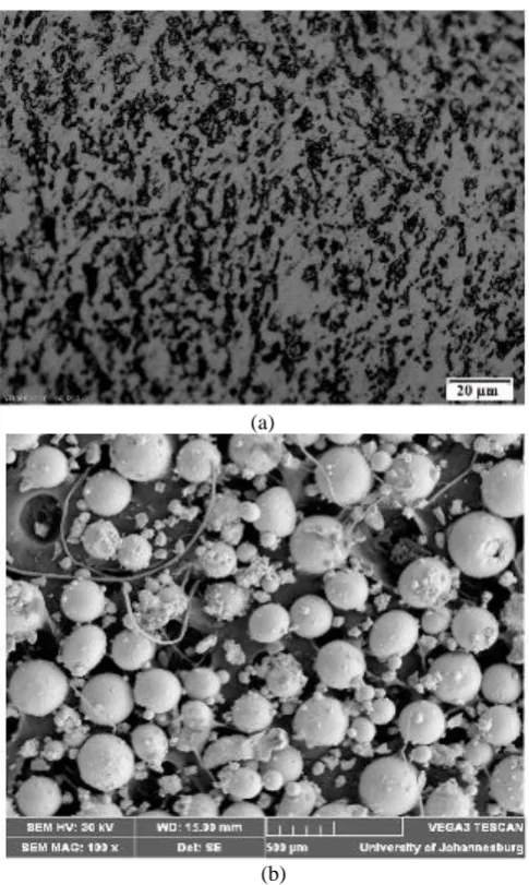
Figure 2. (a) Micrograph of Ti6Al4 substrate (b) SEM micrograph of the Ti6Al4V powder
Conversely, at low powder flow rate, the melt pool is subjected to litter disturbance by the gas which could prevent proper spreading of the deposited powder evenly in the melt-pool. The melt-pool created will be small and the solidification will be rapid thereby promoting the formation of martensitic microstructure similar to what was seen at high scanning speed as shown in Figure 3c. At high gas flow rate, the gas creates agitation in the melt-pool creating proper steering of the powder in the melt-pool. This will assist in the proper melting of the deposited powder could result in bigger melt pool which will in turn solidify slowly and promote the formation of Widmanstätten alpha grains structure similar to what was observed at low scanning speed as shown in Figure 3d.
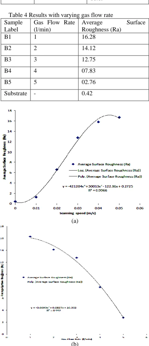
The results of the average surface roughness with varying scanning speed are presented in Table 3 and the results with varying gas flow rate are presented in Table 4. The graph of average surface roughness against the scanning speed is shown in Figure 4a. The graph of average surface roughness against the gas flow rate is shown in Figure 4b. The combined graph of the average surface roughness against the scanning speed and gas flow rate is shown in Figure 5.
(a)
(b)
(c)
(d)
[image:3.595.304.550.44.720.2] [image:3.595.48.291.81.487.2]Table 3 Results with varying gas flow rate Sample
Label
Scanning Speed (m/s)
Average Surface Roughness (Ra)
Substrate - 0.42
A1 0.01 01.22
A2 9.02 06.59
A3 0.03 12.75
A4 0.04 15.82
[image:4.595.47.289.197.760.2]A5 0.05 16.69
Table 4 Results with varying gas flow rate Sample
Label
Gas Flow Rate (l/min)
Average Surface Roughness (Ra)
B1 1 16.28
B2 2 14.12
B3 3 12.75
B4 4 07.83
B5 5 02.76
Substrate - 0.42
(a)
(b)
Figure 4. graph of average surface roughness against the (a) scanning speed (b) gas flow rate.
Figure 5. graph of average surface roughness against the scanning speed and the gas flow rate.
The average surface roughness is seen to increase as the scanning speed was increased. The reason for this could be attributed to the fact that at low scanning speed, there was proper melting of the deposited powder due to the high laser material interaction time and slower cooling of the melt-pool results in low surface roughness. At high scanning speed, the low laser material interaction time that causes the melt-pool to be smaller and results in rapid cooling of the melt pool which could cause cracking of the surface of the deposit because of the martensitic microstructure thereby causing the average surface roughness to be higher. On the other hand, at low gas flow rate the average surface roughness is high because of the martensitic grains seen at low gas flow rate which is similar to what was seen at high scanning speed. The average surface roughness at high gas flow rate is lower because of the Widmanstätten alpha grains structure observed in the microstructure which shows that there was proper melting of the powder and that the cooling rate was slower. This is similar to the observation at low scanning speed. The optimum scanning speed and gas flow rate is shown in Figure 5. The optimum scanning speed and gas flow rate are 0.036 m/s and 3.6 l/min.
IV CONCLUSSION
parameters in order to achieve a better surface finish which will prevent the need for secondary finishing operation.
Acknowledgments
This work was supported by University of Johannesburg research council (URC) and the L'OREAL-UNESCO for Women in Science.
REFERENCES
[1] Scott, J., Gupta, N., Wember, C., Newsom, S., Wohlers, T. and Caffrey, T. (2012). Additive manufacturing: status and opportunities, Science and Technology Policy Institute, Available from: https://www.ida.org/stpi/occasionalpapers/papers/AM3D_33012_Fin al.pdf (Accessed on 11 July 2012)
[2] Pinkerton, A. J., Wang, W. and Li, L. (2008). Component repair using laser direct metal deposition, Journal of Engineering Manufacture, 222: 827-836.
[3] Graf, B., Gumenyuk, A. and Rethmeier, M. (2012). Laser metal deposition as repair technology for stainless steel and Titanium alloys.
Physics Procedia, 39: 376-381.
[4] Gibson, I., Stucker, B., Rosen, D.W., 2009, Additive manufacturing technologies: Rapid prototyping to direct digital manufacturing, Springer
[5] E. Brandl, V. Michailov, B. Viehweger, C. Leyens, (2011). Deposition of Ti–6Al–4V using laser and wire, part I: Microstructural properties of single beads, Surface & Coatings Technology, 206, 1120–1129
[6] R.M. Mahamood, E.T. Akinlabi, (2015), Laser metal deposition of functionally graded Ti6Al4V/TiC, Materials & Design, Volume 84, pp. 402-410,
[7] Z.M, Wang and E.O. Ezugwu, (1997). Titanium Alloys and Their Machinability a Review. Journal of Material Processing Technology,
68, 262-270.
[8] Lütjering, G., Williams, J. C. (2003). Titanium, Springer, Berlin, Germany.
[9] Y., Lu, H.B. Tang, Y.L. Fang, D. Liu, and H.M. Wang, (2012). Microstructure evolution of sub-critical annealed laser deposited Ti–6Al–4V alloy, Materials and Design, 37, 56–63.
[10] R. M. Mahamood, E. T. Akinlabi, M. Shukla and S. Pityana (2012). Functionally graded material: An overview. Proceedings of the World Congress on Engineering (2012) Vol. III , WCE 2012, July 4 - 6, 2012, London, U.K. 1593-1597.
[11] Esther T. Akinlabi, Rasheedat M. Mahamood, Mukul Shukla and Sisa Pityana (2012), Effect of Scanning Speed on Material Efficiency of Laser Metal Deposited Ti6Al4V, Accepted for oral presentation at the World Academy of Science, Engineering and Technology (WASET 2012), 28-28 November 2012.
[12] R. M. Mahamood, E. T. Akinlabi, M. S. and Sisa Pityana (2012), Effect of Laser Power on Material Efficiency, Layer Height and Width of Laser Metal Deposited Ti6Al4V, World Congress of Engineering and Computer Science (WCECS), San Francisco 2012, 24-26 October 2012, vol. 2, pp. 1433-1435.
[13] Y., Lu, H.B. Tang, Y.L. Fang, D. Liu, and H.M. Wang, (2012). Microstructure evolution of sub-critical annealed laser deposited Ti–6Al–4V alloy, Materials and Design, 37, 56–63.
[14] R. M. Mahamood, E. T. Akinlabi, M. Shukla and S. Pityana (2012), Laser Metal Deposition of Ti6Al4V: A Study on the Effect of Laser Power on Microstructure and Microhardness, Accepted for oral presentation at the 2013 International Multiconference of Engineering and Computer Science (IMECS 2013), March 2013.
[15] R. M. Mahamood, E. T. Akinlabi (2014), Effect of Laser Power on Surface Finish during Laser Metal Deposition Process, WCECS 2014. vol. 2, 965-969.
[16] R.M. Mahamood, E. T. Akinlabi, M. Shukla and S. Pityana (2013). Scanning Velocity Influence on Microstructure, Microhardness and Wear Resistance Performance on Laser Deposited Ti6Al4V/TiC Composite. Materials and Design, vol.50, pp. 656-666.
[17] BS EN ISO 4288:1998, Geometric product specification (GPS). Surface texture. Profile method: Rules and procedures for the assessment of surface texture, BSI.