Abstract—Total hip joint replacement is a common procedure to retrieve the lower limp functionality for motorcycle accidents, and hip fracture due to bone weakness. Stress shielding is the factor that determine the duration of the implant functionality, such that the bone will dissolve around the implant which leads implant rejection. In order to perform lower stress shielding CT scan images are converted to finite element model then the optimization is performed for the actual bone modeling. Three methods of optimization are used to perform implant design with minimizing stress shielding as the objective function. Conformal lattice structures, level set shape optimization and solid isotropic material properties-based topology optimization are used. Level set method showed better result by reducing stress shielding to 81%. Conformal lattice structure increased stress shielding due to sharp edges of the metal cellular structure. Solid isotropic material properties topology optimization reduced the stress shielding to 78%.
Index Terms—Femoral implant, level set method, topology optimization, stress shielding
I. INTRODUCTION
otal hip joint replacement is a common procedure to retrieve the functionality of lower limp in aged patients.as an implant, the human body try to reject this forging body due to several mechanisms. These mechanisms called implant failures. Implants are facing the following major failure criterion, biocompatibility issues, and mechanical Issues. Biocompatibility for the implant is particularly important. Implant materials should not be toxic for short and long-term. Corrosion as much as it is physical phenomenon affect mechanical stability directly, but it affects the biological environment; leading to series of serious life-threatening problems. Less severe corrosion issue, which is Ion release also should be considered such that, undesired property which can lead to cellular abnormality problem. This is done by altering the chemical compounds inside the cells such as enzymes and the acidic ribose. Material allergy is a unique property for living body, in such case the implant trigger white blood cells to attack it. Mechanical stability, static and dynamic load resistance, fatigue and crack initiation and propagation, and wear are the major mechanical design aspects. Another problem
Rajaa S. Abass is a lecturer at Al Mamon University College, 14 Ramadan St., Baghdad, Iraq (e-mail: [email protected] ).
Muazez Al Ali M.Sc. is a lecturer in Al Ayen University / College of Dentistry, Iraq ThiQar (email [email protected] )
Musaddiq Al Ali, PhD in structural optimization, Comtech corporation, Hiroshima,Japan (email: [email protected] )
raised which are stress shielding. One of the discussed solutions is to design composite implant to match mechanical properties represented majorly by the Young modulus of elasticity. The major problem of stress shielding is implant mobility, causing implant failure [1].
II. BONE COMPUTERIZED MODELING
There is a valid question which part of the orthopedic process is this work concern with? To answer this question. There are two different way of thinking in design should be discussed: First one is the surgeon and pathologist prospective, and the second one is the Engineering perspective. Starting with the medical point of view; First, the dimensional aspects of the implant and the surgical fixation should be accurate, so the original movements (Rigid multibody spatial description and transformation) [2] and the spatial topography of the bone will be the same as the original and healthy bone. It will cause inflammation, lose functionality, and may need to remove the whole part in order to save the patient life. Material selection will come after to choose nontoxic and appropriate materials. The valid and easy to perform a Surgical technique is important to choose between different designs and / or improving an existing one. Anatomically variation and abnormalities are a challenge in performing surgeries, so the places of the various organs and tissues may have mild to severe variation from patient to another. Radiology is needed to plan the surgery. Radiology can be MRI or CT scan or 2D X-ray or ultrasonic. Engineering design can be summarized as the criteria on which a product be outlined to perform a designated task in the most efficient and reliable way possible. The functionality is one aspect of the mechanical design. Mechanical design taking into consideration major and auxiliary criteria. The major criteria are the safety, relatability, cost, manufacturability, and marketability. The auxiliary criteria are the ethics, legal requirements, consequences, time, and the sociological aspects, marketing in tactical way (current demand) strategically (market saturation and product anticipated technical support revenue). The auxiliary criteria are not less important than the major criteria. Yet the auxiliary criteria need collaborative work of non-engineering expertise. The most vital aspect irreversible aspect of patient management is time. Time of the diagnostic, treating, response, mending and healing is a matter of necessity and utmost importance. Most of the surgeons demanding fully customized orthopedic solution, in shorter time as possible. It is being mentioned that there is a huge demand for one surgery only at which the pre-fixation and the fully customized orthopedic insertion. The technology of computerized imaging, and rapid prototyping may be well developed in
Shape And Topology Optimization Design For
Total Hip Joint Implant
Rajaa S.Abass, Muazez Al Ali ,Musaddiq Al Ali
the near future to deliver the orthopedic before the pre-operation ends. So, the orthopedic will be inserted, and the healing time will be short. Add to that the cost and the medical resources can be optimized in the time of crises (such as earthquake, mass transportation accidents, wars, etc.). Operation type depends on the type of Injury. Bone treatment does not necessitate an outer stress as a cause of injury. It can be caused by diseases such as malignant tumor, or bone decay. In case of malignant tumor, resection is needed. Resection is the process of cutting the tumor with safe margin of no affected tissue. No less than 2.5 cm in general and 1 cm in oral cavity. In case of bone degeneration, an excavation process is used. In this case the hard tissue turned to be soft tissue due to a disease. After healing process, the patient may need scar correction, sensitive area to be desensitize. The area of amputate needs to subject to bearing exercise. The long-term aim of this research is to investigate the recent ideas and perspective of advanced orthopedics and study the ability of delivering such product with the up to date available and practical technical solutions.
III. STRESS SHIELDING BASED COMPUTER AIDED DESIGN
Several works were done to study femoral stem effect in terms of stress distribution of femoral stem [3, 4]. The stem design takes two major tendencies, first one is mechanical design aspects based on size optimization aspects, and the second view is material bone interaction point of view. The optimal size of femoral stem been studied by many researchers for the past few decades. Abdellah Ait Moussa et al [5] studied stress shielding and femoral stem diameter. von Mises stress was the main characteristic stress that was studied. M Reimeringer et al [6] studied the mechanical immobility improvement in terms of stem length. M Shishani et al [7] studied the length factor of the stem in the bone. The second design point view gained increasing attention in the recent decades. D R Sumner et al [8], studied material tissue interaction, the recommendation of porous coating of matching material was introduced. van Rietbergen et al [4] studied material selection option by introducing bone-friendly material coating to the stem surface. F schmidutz et al [9] introduced ceramic outer shell as stem design. Considering mechanical structure biocompatibilities, Stress shielding is an important topic which can be controlled by mechanical properties matching.
IV. TOTAL HIP PROSTHESIS DESIGNING MODEL
[image:2.595.315.541.59.157.2]Total hip replacement is performing due to hip deterioration [10, 11]. Hip replacement divided into two major mechanical structures, the femoral head which concerned more with the tribological aspect is the drive of the design, and the femoral stem, which supports the body load on the femur and distributed within inner space of femoral cavity. Figure. 1 shows the model used in this study. The first step is applying topology optimization to design the stem for minimizing bone stfigress induced by the stem bone interaction. Topology optimization design is done using the following design strategy.
Fig. 1. Femoral implant model
V. IMPLANT DESIGNING CHALLENGES
) ( ) ( 0 ) ( ) ( bone bone bone bone bone cw c cw c dt
d (1)
Where c is an empirical rate constant, is the half-width of the central, normal activity region, the local stress stimulus provided by metal bone contact, is the maximum stress distribution within same case of the healthy bone (before damage and implant). if the difference was smaller enough, it was assumed that no remodeling response would occur. According to that, topology optimization target should be set to minimize maximum strain energy of the bone surrounded by the implant.
VI. STRESS BASED TOPOLOGY OPTIMIZATION
Stress is sensitive toward confined topography. In case of sharp corners within the structure, stress increase dramatically with corner sharpness. To address stress issue in a general view, finite elements should be chosen for the highly susceptible parts. In case of topology optimization; theoretically, the design should be done by the chosen optimization algorithm. In such case, the prior identification of susceptible parts is not a practice issue. To establish topology optimization process, considering SIMP; Initial gray area is necessitating to establish stress distribution of designed domain. However, stress tensor is not giving an estimation of stress state that makes failure. Theories of elastic failure are the key to determine stress states that permitted for maximum estimated structural life. Yield criterion is the envelope that design domain stays within. The maximum allowable stress could be identifying for certain material. Singularity is problem face topology optimization[21]. In order to establish stress criterion as a valid objective function to be extremum, the relationship of scaled stress should be formed satisfying the following; simplicity to decrease unnecessary commotions, physical coherence, and address material discretization directly. Aggregative methods such as p-norm are used to introduce a global stress objective function [22]. To solve stress state, finite element method is the common effective way. Discretization using FEM is adopted in topology optimization to get the design [23]. Stress arises vast constraint number, which degrades solution with increasing resolution of it (i.e. increase element numbers). Such partial differential equation set with vast number of constraint can be considered within Lebesgue space[24, 25]
dt t U Umax ( ): max() (2)
With norm defined by
max max sup 1 , ) ( U U
(3) [image:3.595.313.544.64.142.2]Optimization will consider the first part of norm (3). , which consider as stress norm parameter control the tendency of converging for the optimization process. effect can be shown in Fig. 2
Fig. 2. Topology representative of p-norm function with various normative powers
This will lead to magnifying maximum stress of the system and then it be addressed intensively in optimization process. The objective function that used is taking the form
max 1
max
min
. , |
. . , 0 1
d p P m U P U P i yeild U P
d e d
find
Extermum E
s t d V
(4)
Sensitivity analysis plays a major role in achieving converging results while minimizing computational and time input. First order sensitivity analysis is required to be performed for each iteration. The adjoint variable method is used to develop a unified formulation for representing response variation in terms of variation design.Considering stress based objective function, Cascade function [21, 26]
f
(
(
),
)
max max
|
U
U
df f d df
d d d d
σ u
σ u
(5)
d du
can be replace by adjoint operator to be
d df d dK d d K d f d df vms vms u F u σ σ
1 (6)
Using Adjoint operator such that 1 max max U U f K d
σσ u
(7)
The final derivative is d df d dK d dF d
df T
u
(8)
Here, K is the stiffness matrix depending on the density function ρ. u is the nodal displacement vector, and F is the nodal force vector.
VII. MATHEMATICAL MEDDLING AND OPTIMIZATION
the design, and the femoral stem, which supports the body load on the femur and distributed within inner space of femoral cavity. Figure 3 shows the model used in this study. The first step is applying topology optimization to design the stem for minimizing bone stress induced by the steam bone interaction according to the objective function in equation (4). Topology optimization design is done using the following design strategy-
A. Conformal lattice structure (CLS)
This approach has been introduce into the OptiStruc solver and been investigated by researchers[27-29]. In this method, optimization is done on two stages (cascade approach). First, topology optimization is performed using SIMP method. Density ρ is lower- penalization (i.e. ρ1~1.5) to allow the existence of gray areas (as shown in Fig 3). Gray area is no desired aspect of traditional topology optimization caused it gives the undetermined status of the design, such that SIMP method as a blunt abstract of homogenization approach, is not considering any possibility except the isotropy of the material as one material (in general); so, it will be difficult to determine whether there is or there is not material.
B. SIMP topology optimization
Topology optimization will be performed directly for the density function which is penalized to power 3. The p-norm function is used as shown in (4). The volume fraction is set to be 40% of the original volume. This is to reduce the weight of the implant.
C. Shape optimization with Level set method (LSM)
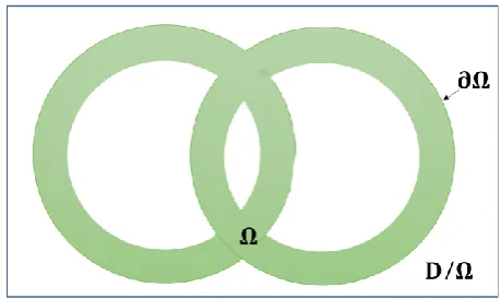
Shape optimization[30] [31] is the part of structural optimization which deals with extremum structural boundaries. The shape is the term describing the outline of the structure. Mathematically the limit of the function by the first order gradient. In shape optimization, besides the objective function, shape representative is being chosen to address boundaries growth. Level set method[32, 33], is one of the methodologies used to perform shape optimization. There are other shape optimization methodologies such as phase filed and Mesh morphing [34]. Phase field, and shape morphing face several challenges, leaving the level set method as the desired method due to its properties, and development. Level set optimization is one of shape optimization methodology which gains more interest recently. The level set method used as finite element adaptation method, which needs no re-mesh. For example; surface detachment[35-37], and crack propagation analysis [38, 39]using extreme finite element method (XFEM). The level set is implicitly representing the domain boundary as the level set function () [40].
/
:
0
)
(
:
0
)
(
/
:
0
)
(
D
[image:4.595.310.540.53.190.2](9)
Fig. 3. Level set scheme.
The domain changing is done by normal velocity vector to the boundary
dt
d. The boundary motion is
changing according to the Hamilton Jacobi equation. 0
) ( )
(
dt d x t
x
(10) Explicitly, for the first instant, might lead to drawback which is introducing not assured regions if it been enclosed in sharp angle boundary. Add to that, boundary discretization might not supply sufficient segments that growth ca relay on[41]. Mathematical implementation has been introduced to improve level set method which overcomes the previously mentioned drawbacks[42].
VIII. RESULTS
Stress shielding results of the designing methods for femoral implants i.e. LSM, CLS and SIMP are been summarized in Table 1. The computational time of the optimization methods has been listed in Table 2
TABLEI
BONE STRESS FOR THE DESIGN METHODOLOGIES
TABLE2
COMPUTATIONAL TIME FOR DESIGNING METHODS
Model Maximum octahedral stress in the bone (N/mm3)
Non-optimized case 7.103e2
CLS 1e3
LSM 1.28e2
SIMP 1.533e2
Model Computational Time ( S)
CLS 4500
LSM 3872
IX. CONCLUSION
Level set method showed the best results in term of reducing the stress shielding of the orthopedic. Topology optimization using SIMP method. The results of LSM and SIMP are close due to the strong convexity of the objective function in term of artificial density. CLS in the other is not reducing the stress shielding activation stress as the two previously mentioned methods. This is due to the localized high contact stress of the tip points of the lattice structure on the bone inner walls. CLS is a considerably good design because it allows the orthopedics to be a scaffold. This can be an advantage in micro gravity regions, such as surgery in space for deep space missions.
REFERENCES
[1] T. Karachalios, C. Tsatsaronis, G. Efraimis, P. Papadelis, G. Lyritis, and G. Diakoumopoulos, “The long-term clinical relevance of calcar atrophy caused by stress shielding in total hip arthroplasty: A 10-year, prospective, randomized study1 1No benefits or funds were received in support of this study,”
The Journal of arthroplasty, vol. 19, no. 4, pp. 469-475, 2004. [2] J. J. Craig, Introduction to robotics: mechanics and control:
Pearson/Prentice Hall Upper Saddle River, NJ, USA:, 2005. [3] J. Mu Jung, and C. Sang Kim, “Analysis of stress distribution
around total hip stems custom-designed for the standardized Asian femur configuration,” Biotechnology & Biotechnological Equipment, vol. 28, no. 3, pp. 525-532, 2014.
[4] B. van Rietbergen, and R. Huiskes, “Load transfer and stress shielding of the hydroxyapatite-ABG hip: a study of stem length and proximal fixation,” The Journal of arthroplasty, vol. 16, no. 8, pp. 55-63, 2001.
[5] A. Ait Moussa, J. Fischer, R. Yadav, and M. Khandaker, “Minimizing Stress Shielding and Cement Damage in Cemented Femoral Component of a Hip Prosthesis through Computational Design Optimization,” Advances in orthopedics, vol. 2017, 2017.
[6] M. Reimeringer, N. Nuño, C. Desmarais-Trépanier, M. Lavigne, and P. Vendittoli, “The influence of uncemented femoral stem length and design on its primary stability: a finite element analysis,” Computer methods in biomechanics and biomedical engineering, vol. 16, no. 11, pp. 1221-1231, 2013.
[7] Y. Shishani, and R. Gobezie, "Does a short stemmed humeral implant really make a difference?."
[8] D. R. Sumner, and J. O. Galante, “Determinants of stress shielding: design versus materials versus interface,” Clinical orthopaedics and related research, vol. 274, pp. 202-212, 1992. [9] F. Schmidutz, M. Woiczinski, M. Kistler, C. Schröder, V. Jansson, and A. Fottner, “Influence of different sizes of composite femora on the biomechanical behavior of cementless hip prosthesis,” Clinical Biomechanics, vol. 41, pp. 60-65, 2017. [10] J. F. Crowe, V. Mani, and C. S. Ranawat, “Total hip replacement in congenital dislocation and dysplasia of the hip,”
JBJS, vol. 61, no. 1, pp. 15-23, 1979.
[11] J. Wedge, and M. Wasylenko, “The natural history of congenital disease of the hip,” Bone & Joint Journal, vol. 61, no. 3, pp. 334-338, 1979.
[12] T. Albrektsson, G. Zarb, P. Worthington, and A. Eriksson, “The long-term efficacy of currently used dental implants: a review and proposed criteria of success,” Int J Oral Maxillofac Implants, vol. 1, no. 1, pp. 11-25, 1986.
[13] C. E. Misch, M. L. Perel, H.-L. Wang, G. Sammartino, P. Galindo-Moreno, P. Trisi, M. Steigmann, A. Rebaudi, A. Palti, and M. A. Pikos, “Implant success, survival, and failure: the International Congress of Oral Implantologists (ICOI) pisa consensus conference,” Implant dentistry, vol. 17, no. 1, pp. 5-15, 2008.
[14] H. Spiekermann, V. K. Jansen, and E.-J. Richter, “A 10-year follow-up study of IMZ and TPS implants in the edentulous mandible using bar-retained overdentures,” International Journal of Oral & Maxillofacial Implants, vol. 10, no. 2, 1995.
[15] S. Cowin, and D. Hegedus, “Bone remodeling I: theory of adaptive elasticity,” Journal of Elasticity, vol. 6, no. 3, pp. 313-326, 1976.
[16] L. Blankevoort, J. Kuiper, R. Huiskes, and H. Grootenboer, “Articular contact in a three-dimensional model of the knee,”
Journal of biomechanics, vol. 24, no. 11, pp. 1019-1031, 1991. [17] R. Huiskes, H. Weinans, and B. Van Rietbergen, “The
relationship between stress shielding and bone resorption around total hip stems and the effects of flexible materials,” Clinical orthopaedics and related research, pp. 124-134, 1992. [18] M. G. Joshi, S. G. Advani, F. Miller, and M. H. Santare,
“Analysis of a femoral hip prosthesis designed to reduce stress shielding,” Journal of biomechanics, vol. 33, no. 12, pp. 1655-1662, 2000.
[19] D. Carter, T. Orr, and D. Fyhrie, “Relationships between loading history and femoral cancellous bone architecture,” Journal of Biomechanics, vol. 22, no. 3, pp. 231-244, 1989.
[20] B. Van Rietbergen, R. Huiskes, H. Weinans, D. Sumner, T. Turner, and J. Galante, “The mechanism of bone remodeling and resorption around press-fitted THA stems,” Journal of biomechanics, vol. 26, no. 4-5, pp. 369-382, 1993.
[21] P. Duysinx, and M. P. Bendsøe, “Topology optimization of continuum structures with local stress constraints,” International journal for numerical methods in engineering, vol. 43, no. 8, pp. 1453-1478, 1998.
[22] M. A. Ali, "Toward fully autonomous structure design based on topology optimization and image processing." p. 7.
[23] G. W. Jang, J. H. Jeong, Y. Y. Kim, D. Sheen, C. Park, and M. N. Kim, “Checkerboard‐free topology optimization using non‐conforming finite elements,” International Journal for Numerical Methods in Engineering, vol. 57, no. 12, pp. 1717-1735, 2003.
[24] M. Diehl, F. Glineur, E. Jarlebring, and W. Michiels, Recent advances in optimization and its applications in engineering: Springer, 2010.
[25] K. Saxe, Beginning functional analysis: Springer Science & Business Media, 2013.
[26] M. A. Al-Ali, M. A. Al-Ali, A. Takezawa, and M. Kitamura, “Topology Optimization and Fatigue Analysis of Temporomandibular Joint Prosthesis,” World Journal of Mechanics, vol. 7, no. 12, pp. 323, 2017.
[27] V. Dakshnamoorthy, “Automated Lattice Optimization of Hinge Fitting with Displacement Constraint,” 2016.
[28] N. S. Sripada, “A Methodology for Topology and Lattice Structure Optimization of a Cargo Drone Motor Mount,” 2018. [29] S. Daynes, S. Feih, W. F. Lu, and J. Wei, “sandwich structures
with 3D printed Functionally graded lattice cores.”
[30] M. A. Ali, “Design Offshore Spherical Tank Support using Shape Optimization,” in Proceedings of the 6th IIAE International Conference on Intelligent Systems and Image Processing 2018, Japan, 2018, pp. 6.
[31] A. T. Musaddiq Al Ali, Mitsuru Kitamura, "Comparative Study of Stress Minimization Using Topology Optimization and Morphing Based Shape Optimization."
[32] M. Y. Wang, X. Wang, and D. Guo, “A level set method for structural topology optimization,” Computer methods in applied mechanics and engineering, vol. 192, no. 1-2, pp. 227-246, 2003.
[33] G. Allaire, F. Jouve, and A.-M. Toader, “Structural optimization using sensitivity analysis and a level-set method,” Journal of computational physics, vol. 194, no. 1, pp. 363-393, 2004. [34] C. Groth, A. Chiappa, and M. Biancolini, “Shape optimization
using structural adjoint and RBF mesh morphing,” Procedia Structural Integrity, vol. 8, pp. 379-389, 2018.
[35] J. Yvonnet, H. L. Quang, and Q.-C. He, “An XFEM/level set approach to modelling surface/interface effects and to computing the size-dependent effective properties of nanocomposites,” Computational Mechanics, vol. 42, no. 1, pp. 119-131, 2008.
[36] J. Chessa, P. Smolinski, and T. Belytschko, “The extended finite element method (XFEM) for solidification problems,”
International Journal for Numerical Methods in Engineering,
vol. 53, no. 8, pp. 1959-1977, 2002.
[37] M. Farsad, F. J. Vernerey, and H. S. Park, “An extended finite element/level set method to study surface effects on the mechanical behavior and properties of nanomaterials,”
International Journal for Numerical Methods in Engineering,
[38] Q. Duan, J. H. Song, T. Menouillard, and T. Belytschko, “Element‐local level set method for three‐dimensional dynamic crack growth,” International Journal for Numerical Methods in Engineering, vol. 80, no. 12, pp. 1520-1543, 2009.
[39] G. Zi, and T. Belytschko, “New crack‐tip elements for XFEM and applications to cohesive cracks,” International Journal for Numerical Methods in Engineering, vol. 57, no. 15, pp. 2221-2240, 2003.
[40] M. Otomori, T. Yamada, K. Izui, and S. Nishiwaki, “Matlab code for a level set-based topology optimization method using a reaction diffusion equation,” Structural and Multidisciplinary Optimization, vol. 51, no. 5, pp. 1159-1172, 2015.
[41] S. Osher, and J. A. Sethian, “Fronts propagating with curvature-dependent speed: algorithms based on Hamilton-Jacobi formulations,” Journal of computational physics, vol. 79, no. 1, pp. 12-49, 1988.