http://www.sciencepublishinggroup.com/j/ajme doi: 10.11648/j.ajme.20170301.12
Thermal Stabilization Based Investigations over Quenching
Media for Spindle in CNC Machining Centers
Kuldeep Verma, Rajendra M. Belokar
Department of Production and Industrial Engineering, PEC University of Technology, Chandigarh, India
Email address:
[email protected] (K. Verma)
To cite this article:
Kuldeep Verma, Rajendra M. Belokar. Thermal Stabilization Based Investigations over Quenching Media for Spindle in CNC Machining Centers. American Journal of Modern Energy. Vol. 3, No. 1, 2017, pp. 10-16. doi: 10.11648/j.ajme.20170301.12
Received: March 27, 2017; Accepted: April 12, 2017; Published: May 8, 2017
Abstract:
The thermal expansion in spindles of computer numeric control (CNC) machines is widespread phenomenon around the world. Thermal change affects the positioning accuracy, repeatability, run out and backlash of the entire machining center. This thermal change in spindle is related with factors like speed and heat. The heat generated during running and machining of work-piece generates considerable amount of heat. This heat further elongates spindle and reduce the performance of spindle and degrade entire efficiency of system. In order to enhance the performance, it is mandatory to dissipate heat at much faster rate than heat generated during machine running and machining. In this paper, thermal equilibrium of spindle front bearing (that is at the nose of spindle) is stabilized up to maximum extent i.e. near to the negligible level. Initially, the spindle stabilized with continuous running at different speed and quenching of spindle by rotating hydraulic oil that will be quenched naturally around the periphery of spindle. Next, hydraulic oil is used for quenching by the circulation of water around the oil reservoir. This removes heat at faster rate. After stabilization of spindle, its impact on the horizontal, vertical and axial plane has been investigated. Finally, analytical investigations have been carried out to prove the validity of spindle stabilization process.Keywords:
Spindle, CNC, Thermal Stabilization, Speed1. Introduction
The heart of CNC machines revolves around the spindle. The two prime functions performed by the spindle are (i) To clamp and unclamp tool (ii) To rotate tool at required speed. With the rotation of spindle, heat generates due to frictional forces which distort and expand the spindle in three planes
i.e. horizontal (XZ plane), vertical (YZ plane) and axial plane. The heat generated during high speed running and machining of spindle should be neutralized up to maximum extent for performance enhancement. Neutralization of spindle needs thermal stabilization at the time of initial start up of machine. This distortion of spindle remains in the three planes which deteriorates the performance of machine. The maximum heat is generated at the nose of spindle and front bearing of spindle. Till today, lots of work has been done and others are in process to thermally stabilize the spindle. Lots of studies and researches have been conducted to neutralize the thermal effects of the spindle. The studies done so far stressed their work on heat generation and neutralisation.
This restricts the thermal growth of spindle at different condition. From the literature review, it is clear that the heat evolved in spindle is due to frictional forces generated during rotary motion of spindle at high speed.
The rest of paper is organized in following sections. Section 2 presents the aim and significance relative to some important related works. Section 3 reports the thermal stabilizations and shift test. Section 4 presents the experimentation scenario and analytical results. Finally, conclusions are made in Section 5.
2. Related Works
The heat at tool work-piece interface can be reduced to maximum extent by cutting fluid. The work done by different researchers in this field are as follows: A new integrated concept for intelligent spindles was proposed by Cao et al.
collision, temperature/thermal error, spindle balance and spindle health. Liu et al. [2] analyzed the spindle thermal errors and developed two methods for investigations. First, thermal-mechanical models of rotating ring and interference assembled geometries were established. This method investigates the thermal variation of relative ring displacements of short cylindrical roller bearing and angular contact ball bearing. Second method was based on the thermal variation models along with heat-fluid-solid coupling FE (finite element) simulation technique. This method measures the spindle linear / angular thermal errors on radial /axial directions by the analytical simulation. Yan et al. [3] developed an optical sensor for the real-time measurement of axial thermal elongation for high-speed spindle of CNC machine tool. Zhao et al. [4] presented simulation of thermal behaviour of a CNC machine tool spindle. It has been realised that water serves as best cooling media than remaining media. The analysis revealed that when water or coolant serves as media, there remain chances of corrosion affecting working and accuracy of machine and its components. Lin et al. [5] designed and reviewed a spindle bearing system of machine tools. Chen et al. [6] proposed a thermo thermo-mechanical error model of hydrostatic spindle for high precision machine tool. The variation of motion errors are influenced by thermal errors which ultimately, deteriorating the accuracy of spindle and machines. Some of the research efforts in this direction are as follows: Yang et al. [7] studied thermal error modelling and compensation for a high-speed motorized spindle. Ahmad and Sarhan [8] investigated the spindle errors motion with thermal changes for high precision CNC machining capability. The aim of this paper is to determine the time taken for the machine to reach a thermal equilibrium condition. As the main sources of error for heat generation are spindle bearing of the machine, the temperature was measured at outer races of the spindle front bearings. The temperature is said to be stabilized when it lasts for fifteen minutes is less than 5% of total rise. The temperature of main spindle front bearing during idle running of spindle at different spindle speed was measured at different interval of time (initially 10 min.). In this paper, a process developed for stabilization, thermal shift and thermal expansion of spindle in horizontal, vertical and axial plane. The developed model has been analyzed theoretically and experimentally. Finally, experimental investigations reveal the authenticity of the proposed model.
3. Thermal Stabilizations and Shift Test
This test has been performed to analyze the data about thermal effects on the main spindle. The test was conducted at spindle with varying speed without cooling of hydraulic oil and with cooling of hydraulic oil by water heat exchanger. The hydraulic oil temperature was also noted. Next, thermal
shift of main spindle was measured in XZ and YZ plane (i.e.
horizontal and vertical plane) and axial directions respectively. The measurement was done at different spindle speed after attaining the temperature stabilization at every speed.
3.1. Computation of Heat Generation
Heat generated by front angular contact bearing of spindle is calculated using the equation (1) given as below:
/ = 1.047 × 10 (1)
= 0.5
= 0.1
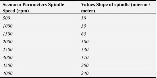
where C represents dynamic load in kgf, denotes coefficient of friction, D describes mean diameter of spindle. The temperature of main spindle front bearing during idle running and testing of spindle at various speed is calculated and measured at different intervals along with the ambient temperature. The computed results, temperature rise of spindle front bearing and thermal distortion of spindle in different plane i.e. horizontal, vertical and axial plane at different speed are shown in table 1 and 2 respectively.
Table 1. Computed results for front bearing temperature rise.
Scenario Parameters Spindle
Speed (rpm) Temperature Values (°C)
500 02
1000 11
1500 21
2000 31
2500 40
3000 50
3500 58
4000 70
Table 2. Computed Results for horizontal, vertical and axial plane.
Scenario Parameters Spindle Speed (rpm)
Values Slope of spindle (micron / meter)
500 10
1000 35
1500 65
2000 100
2500 130
3000 170
3500 200
4000 240
Figure 1. Temperature versus spindle speed.
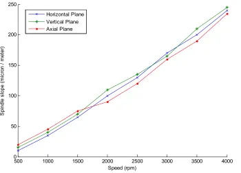
From the figure 1, it has been observed that with the increase in spindle speed, slope with respect to spindle distortion increases up to 1500 rpm. It has been shown in graph thermally.
3.2. Computation of Coefficient of Heat Transfer for Spindle
The heat transfer co-efficient for the spindle has been calculated using the equation (2) as below:
ℎ = 0.664 ( ) /! (2)
"# =$%
&
$ = '( /60
Where h represents coefficient of convection heat transfer,
k denotes thermal conductivity (w/m-deg), n represent revolutions per minute, v describes kinematic viscosity (m2/s), Pr denotes Prandtl number.
4. Experimentation Scenario
The experimentation work initiates with running of spindle at different speed with respect to different time span. The experimentation details are summarized in the table 3.
Table 3. Scenario Parameters.
Scenario Parameters
Spindle Speed (rpm) Time (minutes)
500 180
1000 180 - 270
1500 270 - 315
2000 315-350
2500 350 - 375
Scenario Parameters
Spindle Speed (rpm) Time (minutes)
3000 375 - 410
3500 410 – 440
4000 440 – 465
Machine Type CNC Machining Center
Bearing Single Row Angular Contact (Front Side)
4.1. Spindle Stabilization (Experimental)
Initially, the behaviour of spindle front bearing with cooling of hydraulic oil circulating around the periphery of spindle has been analyzed. Next, analysis has been done on front bearing with the quenching of hydraulic oil by water. The ambient temperature behaviour with the speed has also been discussed. The spindle stabilization process at different speed has been plotted in figure 2. The temperature at different interval of time remains as per the table 1. With respect to different speed and time, thermal analysis has been done for spindle to investigate the behaviour of theoretical and actual value of front spindle bearing. Next, the value computed for temperature with respect to speed and analyzed the behaviour through natural air cooling. Further, the computation would be for temperature variation with speed and evaluated behaviour with oil cooling. Finally, analytical estimations have been carried out through actual values. The temperature measured at the nose of spindle
i.e. at front spindle bearing. The analysis confirmed from the experimental results that at the start of spindle running (upto 500 rpm and 180 minutes) there is gradual increase in the temperature rise of spindle. From 500 to 1500 rpm and time from 180 min to 325 min., the temperature increases at rapid rate. Finally from 1500 to 3800 rpm at time span of 425 min., the temperature hikes at steep rate. At 425 min. and 3800 rpm, the spindle gets stabilized and maximum temperature (61°C) has been achieved. After the stabilization behaviour of spindle speed, the temperature remains constant upto 4000 rpm.
500 1000 1500 2000 2500 3000 3500 4000
0 50 100 150 200 250
Speed (rpm)
S
p
in
d
le
s
lo
p
e
(
m
ic
ro
n
/
m
e
te
r)
Figure 2. Temperature versus spindle speed.
Next, spindle stabilization process has been analyzed with cooling of hydraulic oil by water. This cooled oil has further used for the thermal equilibrium process. It has been analyzed that with the water cooled oil, the spindle gets stabilized within range of 37°C to 40°C.
Table 4. Cooling analysis.
Spindle speed (rpm)
Maximum temperature with cooling by hydraulic oil naturally
Maximum temperature with cooling by hydraulic oil by water
0-4000 61°C 38°C
From the table 4, it has been observed that there is appreciable drop in spindle stablisation temperature when
hydraulic oil gets cooled by water. The drop in temperature has been investigated around 23% less than naturally cooled oil.
4.2. Temperature Rise of Spindle Front Bearing
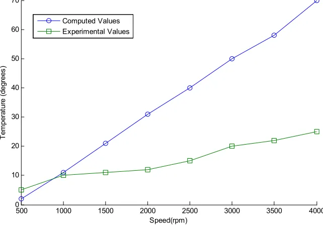
Next after examination of spindle stabilization process, the temperature rise at the nose of spindle has been evaluated. The spindle bearing is placed at the front side which remains in closed contemporary to spindle for entire investigations. The speed versus temperature graphs of spindle front bearing are shown in figure 3. The theoretical and experimental predictions of spindle front bearing temperature rises with the cooling of hydraulic oil at different spindle speed are shown in figure 3.
Figure 3. Temperature speed analysis.
0 5 10 15 20 25 30 35 40
30 35 40 45 50 55 60 65
Speed (rpm) in thousands
T
e
m
p
e
ra
tu
re
i
n
d
e
g
re
e
s
Calculated Values With oil cooling Actual Values
500 1000 1500 2000 2500 3000 3500 4000
0 10 20 30 40 50 60 70
Speed(rpm)
T
e
m
p
e
ra
tu
re
(
d
e
g
re
e
s
)
From the predicted and actual results, it has been extracted that there is significant difference between computed and actual values. There is rapid growth in the temperature rise with respect to spindle speed as computed from the equation (1). In actuality, there is gradual increase in the rise of temperature at front side of spindle. This is due to the spindle stabilization process that has been performed at the initial stage of experimentation.
C. Thermal Distortion in Three Planes (Experimental)
Next, after examining the stabilization and temperature rise, the thermal shift of spindle investigated. The thermal growth of spindle has been computed in three directions i.e.
horizontal, vertical and axial computed as per table 2 and shown in the figure 1. First, experimental results of thermal distortion of spindle in horizontal plane at different speed have been shown in figure 4. The stiffness of spindle relies on the thermal growth and remains directly proportional to speed.
Figure 4. Spindle speed versus thermal distortion.
The figure 4 shows the impact of speed on thermal distortion of spindle in X-Z direction. It has been analyzed from the figure 4 that at 500 rpm deformation of spindle remains six to eight microns. It remains nearly equal upto 1500 rpm afterwards this starts increasing from eight microns to twenty microns upto 3000 rpm. Next, from 3000 to 3500 rpm, there is steep increase in the thermal distortion of spindle which remains fifty microns. Finally, from 3500 to 4000 rpm, it further increases and remains fifty five microns
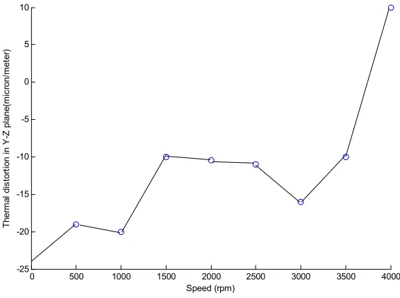
(maximum). Overall, this has been concluded that with the increase in speed, thermal distortion also increases. Second, experimental results of thermal distortions of spindle in vertical plane at different speed are shown in figure 5. With increasing speed, more and more heat is generated. The heat generated distorts the positioning accuracy and run-out of spindle which further decreases efficiency of spindle and degrades the overall performance of CNC machining centers.
Figure 5. Thermal distortions in Y-Z plane.
500 1000 1500 2000 2500 3000 3500 4000
-60 -50 -40 -30 -20 -10 0
Speed (rpm)
T
h
e
rm
a
l
d
is
to
rt
io
n
i
n
X
-Z
p
la
n
e
(
m
ic
ro
n
/m
e
te
r)
0 500 1000 1500 2000 2500 3000 3500 4000
-25 -20 -15 -10 -5 0 5 10
Speed (rpm)
T
h
e
rm
a
l
d
is
to
rt
io
n
i
n
Y
-Z
p
la
n
e
(m
ic
ro
n
/m
e
te
The figure 5 describes the effect of speed on the thermal distortion of spindle in Y-Z direction. It has been analyzed from the figure 5 that in the beginning of cycle i.e. at 500 rpm deformation of spindle remains highest at the negative end. With increase in speed from 500 to 3500 rpm, there is mixed behaviour on negative side means at some points it is increasing and at some points it is decreasing. At last from 3500 to 4000 rpm, there is appreciable increase in the thermal distortion of spindle from negative side to positive side and there remains sharp increase of twenty microns (in
total) from minus ten microns to ten microns.
Third, experimental results of thermal distortion of spindle in axial plane at different speed are shown in figure 6. The axial direction has been considered for experimentation remains in the machining direction. In this direction, cutting tool remains in actual contact with the work-piece. The maximum heat generated and thermal deformation remains in this direction. This plane distorts maximum positioning accuracy and repeatability of machines along with the work-piece. The plot for axial i.e. Z direction is shown below:
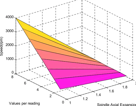
Figure 6. Plot of speed versus axial expansion.
The figure 6 describes the effect of speed on the thermal distortion of spindle in Z direction. It has been analyzed from the figure 6 that in the beginning of cycle i.e. at 500 rpm axial expansion of spindle starts from sixty microns. With increase in speed from 500 rpm to 1000 rpm, there is no significant rise in axial expansion and value remains seventy microns. From 1000 to 3000 rpm, there is gradual increase in spindle expansion and the value remains ninety microns. After 3000 rpm, thermal axial expansion value remains constant up to 4000 rpm.
5. Conclusions
There is an absolute need to address the thermal problem associated with the spindles to enhance the performance of CNC machines. Rotation of spindle generates considerable amount of heat that creates the thermal in-equilibrium. From the literature review, it has been extracted that around three fourth of total error in machine tool arises due to thermal changes in spindle. In this paper, the thermal effects on spindle from theoretical and analytical aspects investigated. It is evident from the investigations that maximum heat generation in spindle are due to the rotation of spindle at high speed and its effect on front bearing mounted at the nose of spindle. The maximum heat and thermal effects lie in this
region. Initially, the thermal stabilization of main spindle front bearing and hydraulic oil circulation around the periphery of spindle explored. Next, computation and analysis remains on the thermal stabilization of main spindle front bearing with cooling by hydraulic oil and circulating water around the periphery of oil. The observation was on the thermal effects from both theoretical and analytical aspects. Next, thermal shift of main spindle in XZ (horizontal), YZ
(vertical) and axial plane has been analyzed. Next, proposed work investigated that among the three planes, thermal shift remains maximum in axial direction on the consistent patterns of references [9-10]. In the future, focus of work remains on analysis of spindle from different facets i.e.
analyzing spindle cooling from different cooling media, with respect to speed and other key factors.
References
[1] Hongrui Cao et al. The concept and progress of intelligent spindles: A review, International Journal of Machine Tools and Manufacturer. 2016.
[2] Teng liu et al. Analytical Modelling for Thermal Errors of Motorized Spindle Unit, International Journal of Machine Tools and Manufacturer. 2016.
1
1.2
1.4 1.6 1.8
2
0 2 4 6 8 0 1000 2000 3000 4000
Spindle Axial Expansion (Micron/meter) Values per reading
S
p
e
e
d
(r
p
m
[3] Zih Siang Yan et al. Measurement of the thermal elongation of high speed spindles in real time using a cat's eye reflector based optical sensor, Sensors and Actuators A: Physical Volume 221, 1 January 2015, Pages 154–160. 2015.
[4] Zhao haito et al. Simulation of thermal behaviour of a CNC machine tool spindle, International journal of machine tool and, pp. 1003-1070, 2007.
[5] Lin et al. Dynamic Models and Design of Spindle-Bearing Systems of Machine Tools: A Review, International Journal of Precision Engineering and manufacturing, Vol. 14, No. 3, pp. 513-521. 2013.
[6] Chen et al. Thermal error of hydrostatic spindles, Precision Engineering Journal, Precision Engineering 35 (2011) 512– 520. 2011.
[7] Jun Yang, Hu Shi, Bin Feng, Liang Zhao, Chi Ma, Xuesong Mei: Thermal error modelling and compensation for a high speed motorized spindle. International Journal Advanced Manufacturing Technology (2015) 77: 1005-1017. 2015. [8] Ahmad A. D. Sarhan: Investigate the spindle error motions
from thermal change for high precision CNC machining capability. International Journal of Advanced Manufacturing Technology 70: 957-963. 2014.
[9] Kuldeep Verma, R. M. Belokar. Optimized Investigations over Diameter and Distance Based Factor towards Rigidity and Accuracy of Spindle in CNC Machining Centers. Journal for Manufacturing Science and Production. Volume 16, Issue 2, Pages 115–121, ISSN (Online) 0375, ISSN (Print) 2191-4184, DOI: 10.1515/jmsp-2015-0026, June 2016.
[10] Kuldeep Verma, R. M. Belokar. Pervasive Investigations of Critical Speed over Weight and Deflection Factors of Shaft Assembly in CNC Ball Screw System, Hindawi Publishing Corporation International Journal of Manufacturing Engineering Volume 2016, Article ID 6198278, 6 pages http://dx.doi.org/10.1155/2016/6198278
Biography
Kuldeep Verma born in Kalka (Haryana), India. He is pursuing Ph.D. degree in Production and Industrial Engineering from PEC University of Technology, Chandigarh, India. He holds Master degree in Manufacturing from Birla Institute of Technology (BITS), Pilani, Rajasthan and Bachelor of Engineering in Mechanical Engineering from Maharishi Dayanand University, Rohtak. He has published papers in Journal for Manufacturing Science and Production, USA and Journal of Manufacturing Engineering, USA. His fields of interests are computer numeric control machines, designing, manufacturing, optimization and project development.