ISSN 2348 – 7968
798
Mono Composite Leaf Spring – Design and Analysis by using FEA
Under Static Load Condition
P. RAVINDRANATHA REDDY1, K. SURESH KUMAR2
1 Assistant Professor, Department of Mechanical Engineering, Annamacharya Institute of Technology and Sciences,
Rajampet, Kadapa(Dist.), Andhra Pradesh, India - 516126
2 Associate Professor, Department of Mechanical Engineering, K.S.R.M. College of Engineering,
Kadapa, Andhra Pradesh, India - 516003
1.
Abstract
The behaviour of vehicle significantly affects by the suspension system, i.e., vibrational characteristics along with ride comfort, stability of direction, etc. Leaf springs commonly used in suspension system of automobiles are subjected to millions of varying stress cycles leading to fatigue failure. If the unsprung weight is reduced, then the fatigue stress induced in the leaf spring is also reduced. Leaf spring contributes about 10-20% of unsprung weight. Hence, even a little amount of reduction in weight of the leaf spring leads to enhance the passenger comfort as well as reduces the vehicle cost. Therefore the aim of this paper is to design a spring with minimum weight that is capable of carrying given static external forces without failure. A single leaf with variable thickness and width for constant cross sectional area of unidirectional Glass Fiber Reinforced Plastic (GFRP) with similar properties as that of a multi-leaf spring is designed and analyzed by considering bending stress and deflection as design constraints using ANSYS 13.0. C-Program has been used for the design of constant cross-section leaf spring. The results showed that spring width decreases and thickness increases from the spring eyes towards the axle seat. The finite element results obtained for stresses and deflection using ANSYS software are verified with analytical results and found that results are close to the analytical values. Compared to the steel spring, the composite spring has stresses that are much lower and the spring weight is nearly 80% lower.
Keywords: Composite material, Leaf Spring, Weight,
Analysis, C-Language
2.
Introduction
Weight reduction is very important factor of automobile manufacturer to save the natural resources and optimize energy. Weight reduction can achieve primarily
by the use of better material, optimization of design and advanced manufacturing processes. In an automobile the leaf spring used for suspension is one of the potential items for weight reduction as it participates about ten to twenty percent of the unsprung weight. It helps the vehicle in achieving the better riding qualities. It is very well known those springs are designed to receive and store energy and then release it. Hence, the material strain energy becomes an important factor in designing the springs. The relationship of the specific strain energy can be expressed as
U=(σ2/ρE) (1)
ISSN 2348 – 7968
799 absorption but also carries lateral loads, brake torque,
driving torque.
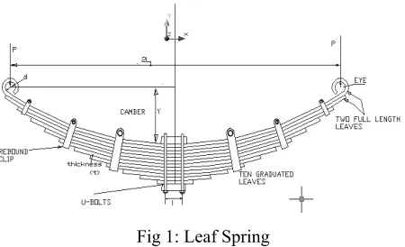
Fig 1: Leaf Spring
The leaf spring has its advantage over helical spring is that the ends of the spring may be allowed to move along a definite path as it deflects to act as a structural member in addition to energy absorbing device. The geometry of the Steel leaf spring is shown in Fig. 1.
2.
Specification of the Problem
The weight of the existing steel leaf spring is about 15Kg. The main aim of the paper is to reduce the weight of steel leaf spring by replacing 7-leaf rear suspension spring with Mono-leaf composite spring. To compare the performance of the steel leaf spring with composite leaf spring the design requirements are taken almost the same as that of the conventional steel leaf spring.
3.
Design Parameters of the Steel Leaf
Spring
Table 1: Design parameters
Parameter Value Max load acting on the spring, 2W 8183N
Max deflection allowable, max 150mm
Static load acting on one end of the spring, W
4091.5N
Distance between eyes, (span) 2L 1130mm
Ineffective length 80mm
Camber required for the spring, C 275mm
Number of leaves, n 7
Width of each leaf, b 45mm
Thickness of each leaf, t 10mm
Spring rate of the leaf spring, K 25kN/m
4. Design of Composite Mono Leaf Spring
Considering several types of vehicles that have leaf springs and different loading on them, mono composite leaf spring of various kinds have been developed.
The cross sections of following types of mono-leaf composite leaf spring for easy manufacturing are considered.
1. Constant thickness, constant width design. 2. Constant thickness, varying width design. 3. Varying width, varying thickness design.
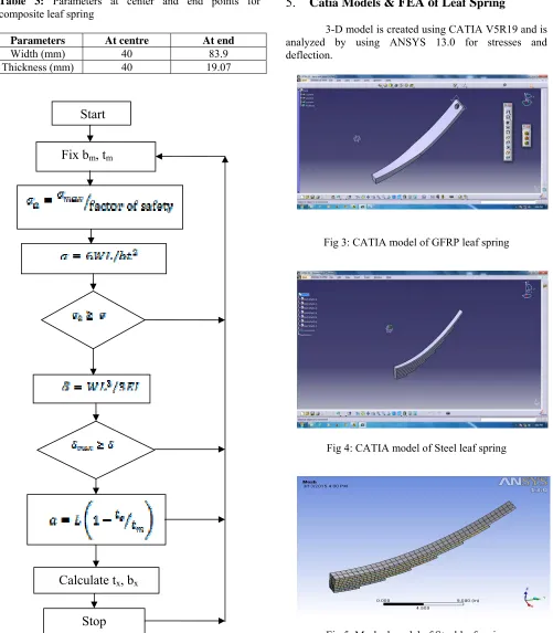
In this paper, only a mono-leaf composite leaf spring with varying width and varying thickness is designed and analyzed. Computer algorithm using C-language has been used for the design of constant cross-section leaf spring. The obtained results explained that spring width decreases and thickness increases from the spring eyes towards the axle seat. Fig. 2 represents flowchart of computer algorithm for design of composite leaf spring. The various parameters of composite leaf spring are shown in Table 3. The material properties of E-Glass/Epoxy [2] are listed in Table 2.
Table 2: Material properties of E-Glass fiber
Parameter Value Tensile modulus along X-direction
(EX) 34000 MPa
Tensile modulus along Y-direction
(Ey) 6530 MPa
Tensile modulus along Z-direction
(Ez) 6530 MPa
Tensile strength of the material 900 MPa Compressive Strength of the material 450 MPa Shear modulus along XY-direction
(GXY) 2433MPa
Shear modulus along YZ-direction
(GYZ) 1698 MPa
Shear modulus along ZX-direction
(GZX) 2433 MPa
Poisson ratio XY-direction (NUXY) 0.217
Poisson ratio YZ-direction (NUYZ) 0.366
Poisson ratio ZX-direction (NUZX) 0.217
Mass Density of the material (ρ) 2.6e-6 kg/mm3
Coefficient of thermal expansion (α) 0.95 x 10⁻⁵/
ºC
Water absorption capacity 0.25% in
ISSN 2348 – 7968
800 Table 3: Parameters at center and end points for
composite leaf spring
Parameters At centre At end
Width (mm) 40 83.9
Thickness (mm) 40 19.07
Fig 2: Flow Chart
5.
C
atiaM
odels& FEA o
fL
eafS
pring3-D model is created using CATIA V5R19 and is analyzed by using ANSYS 13.0 for stresses and deflection.
Fig 3: CATIA model of GFRP leaf spring
Fig 4: CATIA model of Steel leaf spring
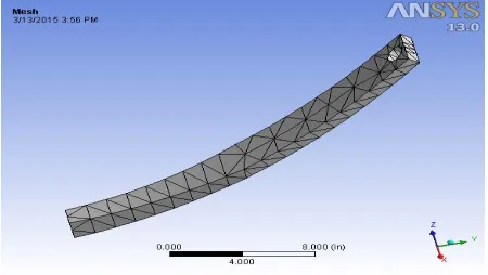
Fig 5: Meshed model of Steel leaf spring
Start
Fix b
m, t
mCalculate t
x, b
xISSN 2348 – 7968
801 Fig 6: Stress distribution in Steel leaf spring
Fig 7: Deformation in Steel leaf spring
Fig 8: Meshed model of composite leaf spring
Fig 9: Stress distribution in GFRP leaf spring
Fig 10: Deformation of GFRP leaf spring
Fig 11: Stress distribution of CFRP leaf spring
Fig 12: Deformation of CFRP leaf spring
6.
Results and Discussion
ISSN 2348 – 7968
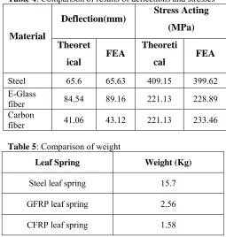
802 Table 4: Comparison of results of deflections and stresses
Material
Deflection(mm) Stress Acting (MPa)
Theoret
ical FEA
Theoreti
cal FEA
Steel 65.6 65.63 409.15 399.62
E-Glass
fiber 84.54 89.16 221.13 228.89
Carbon
fiber 41.06 43.12 221.13 233.46
Table 5: Comparison of weight
Leaf Spring Weight (Kg)
Steel leaf spring 15.7
GFRP leaf spring 2.56
CFRP leaf spring 1.58
The weight of the leaf spring is reduced considerably about 80% by replacing steel leaf spring with composite leaf spring. Thus, the aim of the unsprung mass is reached to maximum extent. The induced stresses in the composite leaf spring are much lower than that of the steel spring.
7.
Conclusion
The steel leaf spring is replaced with a composite one. The aim was to obtain a spring with minimum weight which is capable of carrying given static external forces by constraints limiting stresses and displacements. The weight of the leaf spring is reduced considerably about 80% by replacing steel leaf spring with composite leaf spring. Thus, the aim of the unsprung mass is reached to maximum extent. The induced stresses in the composite leaf spring are much lower than that of the steel spring.
Analysis has been done for unidirectional E-Glass/Epoxy and CFRP mono composite leaf springs. Both the composite materials can be able to with stand given static forces, but CFRP is having less impact strength and more costly than GFRP leaf spring, so GFRP leaf spring is recommended to replace the conventional steel leaf spring. Since, the composite spring is designed for same stiffness as that of steel leaf spring, both the springs are considered to behave almost same in vehicle
stability. The major disadvantage of composite leaf spring is chipping resistance. The matrix material is about to chip off when it is subjected to a poor road environments (that is, if some stone hit the composite leaf spring then it may produce chipping) which may break some fibres in the lower portion of the spring. This will be result in a loss of capability to share flexural stiffness. But it depends on the condition of the road. In normal road condition, this type of problemwill not occur. Composite leaf springs made of polymer matrix composites have high strength retention on ageing at severe environments.
Notations
bm – width at middle (mm); tm – thickness at middle (mm);
σb – design bending stress (N/mm2); δ– deflection of the
spring (mm); δmax – camber of the spring (mm); a – distance from the centre to which the width varies with thickness; L – distance between the centres of the eye[span] (mm).
References
[1] Daugherty R. L., “Composite Leaf Springs in Heavy Truck Applications”, K. Kawata, T.Akasaka (Eds). Composite Materials Proceedings of Japan-US Conference Tokyo, 1981, pp. 529 – 538.
[2] Tanabe, K., Seino, T., Kajio, Y. Characteristics of Carbon/Glass Fiber Reinforced Plastic Leaf Spring, SAE 820403 1982: pp. 1628 – 1634.
[3] Vijayarangan S, Ganesan N, “Static Stress Analysis of a Composite Bevel Gear using a Three-dimensional Finite Element Method”, Computer Structures, vol.51, no. 6, 1994, pp. 771 – 783.
[4] Yu W. J., Kim H. C., “Double Tapered FRP Beam for Automobile Suspension Leaf Spring”, Comp. Structure, 1998, pp. 279 – 300.
[5] Rajendran I, Vijayarangan S, “Optimal Design of a Composite Leaf Spring using Genetic Algorithms”, International Journal of Computer and Structures, vol.79, 2001: pp. 1121 – 1129.
[6] Rajendran I, Vijayarangan S, “Design and Analysis of a Composite Leaf Spring”, Journal of Institute of Engineers India, vol. 82, 2002, pp. 180 – 187.
[7] Gardiner C.P, Mathys Z, “Tensile and Compressive Properties of FRP Composites with Localised Fire Damage”, Applied Composite Materials, vol. 9, 2002, pp. 353–367.