Novel Dual-Band Bandpass Filter Based on Shorted
Rectangular Patch Resonator
Kuan Deng1, *, Caiyue Wen1, Fei Li2, and Wenquan Che2
Abstract—A novel dual-band bandpass filter based on shorted rectangular patch resonator is proposed and experimentally studied. The resonant modes and frequencies of the shorted rectangular patch resonator are analyzed. Based on miniature structure of the new resonator, a novel dual-band bandpass filter with good out-of-band performance is designed for demonstration. The experimental results agree well with numerical simulations.
1. INTRODUCTION
Due to the rapid development of wireless technology over past few years, microwave circuits that can handle signals at multiple frequency bands have become an attractive feature for the reduction of system size and cost. In the past, the dual-band bandpass filters were realized with two circuits for respective frequency bands. However, this kind design requires large circuit size and extra impedance-matching network for each module. To lower the cost and reduce the circuit area, a single circuit capable of operating in two bands is more popular. Among the popular multiple frequency resonators, stepped impedance resonators (SIR) [1, 2] and T-shaped resonators [3, 4] are usually used to design these filters. However, extremely high impedance ratio are sometimes needed to meet the required frequencies, which make it difficult to manufacture.
In general, rectangular patch structures have been widely used in microwave antennas and filters [5– 8]. In those applications, half-wavelength rectangular patch usually operates at the fundamental resonant modes TM10 and TM01 [6] and quarter-wavelength rectangular patch usually operates at the fundamental resonant mode TM10 and the harmonic resonant mode TM30 [6]. Etching slots on the patch could extend the current distribution of resonant mode and can reduce the patch size [7, 8].
In this letter, we propose a novel dual-band bandpass filter based on shorted rectangular patch resonator (quarter-wavelength rectangular patch) and its resonant modes and frequencies are also analyzed. The fabrication of the dual-band bandpass filter based on the shorted rectangular patch is very simple, for it does not require narrow lines to realize high characteristic impedance. To reduce the size of filter, two slots are etched in the shorted rectangular patch resonator, and nearly achieve size reduction of 40%. Finally, a sample of filter based on miniaturized shorted rectangular patch resonators is fabricated and measured to validate the predicted design.
2. FILTER DESIGN
2.1. Resonator Analysis
Figures 1(a)–(b) show the structures of the traditional and proposed shorted rectangular patch resonators. By adding shorted wall at middle symmetry plane of traditional rectangular patch resonator and it can be split in half, then the shorted rectangular patch resonator can be realized.
Received 31 January 2015, Accepted 20 March 2015, Scheduled 13 April 2015
* Corresponding author: Kuan Deng ([email protected]).
(a) (b)
Figure 1. Structures of resonators, (a) traditional rectangular patch resonators, (b) shorted rectangular patch resonators.
(a) (b) (c) (d)
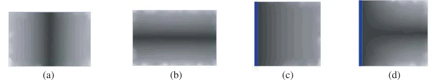
Figure 2. Electric-field distributions, (a) resonant modes 1 of traditional rectangular patch, (b) resonant modes 2 of traditional rectangular patch, (c) resonant modes 1 of shorted rectangular patch, (d) resonant modes 2 of shorted rectangular patch.
According to the theory of traditional rectangular patches [5], traditional rectangular patch resonators exist two resonant modes. The two resonant modes are quasi-TEM half-wavelength resonator alongx-axis direction andy-axis direction. The electric-field distributions of the traditional rectangular patch resonant are shown in Figs. 2(a)–(b). We name the resonant mode alongx-axis direction as mode 1, and the resonant mode along y-axis direction as mode 2. When ignoring the fringing field [5], the resonant frequencies of dominant mode of two modes can be expressed as:
fx1 = c0
4Lx√εr, fy1 = c0
2Ly√εr (1)
where, c0 is the velocity of light in free space and εr the relative dielectric coefficient of the substrate. Next, we analyze shorted rectangular patch resonator along x-axis direction and y-axis direction, which are orthogonal.
Along thex-axis direction, cross-section of shorted rectangular patch resonator is shown in Fig. 3(a). The transmission line in Fig. 3(a) is two-conductor structure, similar to microstrip line. Based on the microwave theory [9], the transmission mode of this structure is quasi-TEM mode, generally simplified as TEM mode. Then, the resonator are shorted at one terminal and open at another terminal, which constitute a quarter-wavelength resonator. We name the resonant frequencies of quasi-TEM modes as fx. As the resonator in case of this mode is a quarter-wavelength resonator, when ignoring the fringing field,fx can be expressed as:
fx= (2k−1)c0
4√εrLx , (k= 1,2,3, . . .) (2) When k= 1, Equation (2) become:
fx1 = c0
4Lx√εr (3)
(a) (b)
Figure 3. Cross sections of shorted rectangular patch resonators, (a) along x-axis direction, (b) along y-axis direction.
structure [10]. The transmission mode of this structure is TE-mode. Then, boundary conditions of the resonator are open at two terminals, which constitute a half-wavelength resonator. According to [10], we name the resonant frequencies of TE modes as fTEm−1/2,0,n, as can be expressed as:
fTEm−1/2,0,n = c0 2√εr
2m−1 2Lx
2
+
n
Ly
2
(4)
When k= 1, Equation (4) became to:
fTE0.5,0,1 = c0 2√εr
1 2Lx
2
+
1 Ly
2
(5)
wherefTE0.5,0,1 is the resonant frequency of the dominant mode of TE modes, which is not equal to fy1 in Equation (1). From the field distributions shown in Figs. 2(b) and (d), the shorted wall changes the distributions of traditional rectangular patch, so the two resonant frequencies are not the same.
2.2. Miniaturization of the Resonator
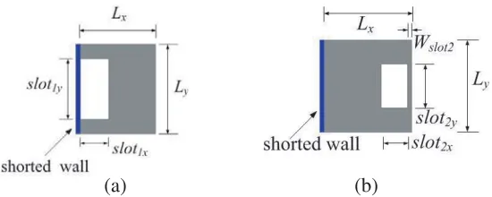
As we know, the etched slot on patch will extend current path of the resonant modes, and thus can decrease the resonant frequency [7, 8]. To reduce the size of the shorted rectangular patch resonator, the following two methods will been studied, which etching slot are near the shorted wall and opposite to the shorted wall, as shown in Fig. 4.
Figure 4(a) shows the structure of shorted rectangular patch with etching slot near the shorted wall. Figs. 5(a)–(b) show the simulated results of resonant frequency with one parameter are different while another parameters fixed. As we can see, the resonant frequency 2 becomes low asslot1xincreases, while the resonant frequency 1 nearly becomes unchanged. Resonant frequency 1 becomes low asslot1y increases, while the resonant frequency 2 nearly becomes unchanged. When the first two resonant modes of the rectangular patch with shorted wall are used to design dual-band filter, the resonant frequency becomes lower as slot1x and slot1y increase. This etching method could achieve size reduction about 30%.
(a) (b)
1 2 3 4 5 6 7 8 slot (mm)
(a) (b)
1x
1 2 3 4 5 6 7 8
slot (mm)1y 4.0 3.5 3.0 2.5 2.0 Frequency (GHz) 4.0 3.5 3.0 2.5 2.0 Frequency (GHz) 1.5 f f 1 2 f f 1 2
Figure 5. Simulated resonant frequencies of the structure in Fig. 4(a), (a) slot1y = 5 mm, (b)
slot1x = 5 mm.
1 2 3 4 5 6 7 8
slot (mm)
(a) (b)
2x
1 2 3 4 5 6 7 8
slot (mm)2y 6.0 5.5 5.0 4.5 4.0 3.5 3.0 2.5 2.0 Frequency (GHz) f f 1 2 f f 1 2 6.0 5.5 5.0 4.5 4.0 3.5 3.0 2.5 2.0 Frequency (GHz)
Figure 6. Simulated resonant frequencies of the structure in Fig. 4(b), (a) slot2y = 5 mm, (b)
slot2x = 5 mm.
Figure 4(b) shows the structure of shorted rectangular patch with etching slot opposite to the shorted wall. Figs. 6(a) and (b) illustrate the simulated results of resonant frequency with one parameters different while another parameter is fixed and Wslot2 = 0.4 mm. As we can see, the resonant frequency 2 becomes lower asslot2x increases, while the resonant frequency 1 changes slightly. Resonant frequency 1 increases as slot2y increases, while resonant frequency 2 changes slightly. Etching slot opposite to the shorted wall can extend the current path of the resonant frequency 2, so to achieve reducing the resonant frequency 2. This etching method cannot reduce the first two resonant frequencies simultaneously, if decreasing the first resonant frequency, it is necessary to increaseLx, which increases the overall area.
As we can see, the above two methods mentioned are difficult to decrease the first two resonant frequency simultaneously. So, the combination of the two etching methods necessary. Two slots are etched on the patch, then we get miniature shorted rectangular patch resonators, as shown in Fig. 10.
2.3. Filter Design
Based on shorted rectangular patch resonator, a 3-stage dual-band bandpass filter can be implemented as shown in Fig. 7, operating at 2.45 GHz and 5.2 GHz. The substrate with relative dielectric constant 9.2 and thickness of 1.016 mm is used. According to Equations (3) and (5), we could getLx= 10.1 mm, Ly = 10.7 mm.
Figure 7. 3-stage dual-band bandpass filter based on shorted rectangular patch resonators.
6.0 5.5 5.0 4.5 4.0 3.5 3.0 2.5 2.0
Frequency (GHz)
7.0 6.5 5 mm 9 mm 13 mm 0
-10
-20
-30
-40
-50
-60
-70
Magnitude (dB)
Figure 8. Simulated results of dual-band bandpass filter in different L2.
6 5 4 3 2
Frequency (GHz)
7 0
-10
-20
-30
-40
-50
-60
Magnitude (dB)
S11
21
S
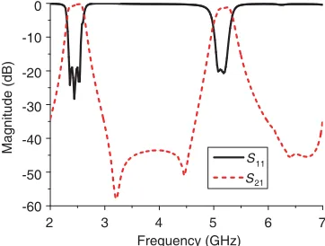
Figure 9. Simulated frequency responses of dual-band dual-bandpass filter.
Figure 10. Proposed dual-band bandpass filter based on miniature shorted rectangular patch resonators.
g1 = 0.2 mm, g2 = 0.9 mm, W1 = 0.3 mm, W50= 1.05 mm (50 Ω microstrip width). L1 and L2 have a great impact on the performance of the filter. Changing the length of L2 respectively equal to 5 mm, 9 mm, 13 mm while keep L1 = 5.45 mm, the simulated frequency responses of the filter is shown in Fig. 8. From the Fig. 8, we can see a transmission zero is obtained when the length of L1+L2 is half-wavelength, this characters similar to DBR (dual-behavior resonators) [3, 11]. So the L-type branch coupling structure could increases the out-band rejection performance of the filter.
Tuning by the full wave electromagnetic (EM) simulator, we got the final values of all dimension parameters: Lx = 10 mm, Ly = 10.5 mm, L1 = 6 mm, L2 = 12.8 mm, g1 = 0.2 mm, g2 = 0.8 mm, W1 = 0.3 mm, W50 = 1.05 mm and the simulated frequency responses are showed in Fig. 9. The simulated fractional bandwidths are 124% at 2.46 GHz and 635% at 5.19 GHz, respectively. The corresponding return losses are greater than 19 dB and 19.5 dB. The passband insertion losses are 0.22 dB for the first passband and 0.76 dB for the second passband.
To reduce the patch size, two slots are etched on the patch, and then we get miniature shorted rectangular patch resonators, as shown in Fig. 10. Two slots extend current path of the two resonant modes, which can reduce the resonant frequency. Tuning by the full wave electromagnetic (EM) simulator, the final sizes are obtained as: Lx = 9 mm, Ly = 7 mm, L1 = 5.8 mm, L2 = 13 mm, g1 = 0.2 mm, g2 = 0.8 mm, W1 = 0.3 mm, W2 = W3 = 0.4 mm, slot1x = 2 mm, slot1y = 5.4 mm,
6 5 4 3 2
Frequency (GHz)
7 -40
-60
Magnitude (dB)
-80
(a) (b)
simulated S simulated S
measured S measured S
11 21 11 21
Figure 11. (a) Simulated and measured frequency responses of the proposed dual-band bandpass filter. (b) Photograph of the proposed filter.
for the second passband.
Compared to conventional shorted rectangular patch resonators, the size of miniature shorted rectangular patch resonators reduced from the 10 mm×10.5 mm to 9 mm×7 mm, with size reduction nearly 40%.
3. MEASURED RESULTS AND DISCUSSIONS
The measurement is carried out with Agilent-8722ES vector analyzer. The simulated and measured frequency responses of this filter are shown in Fig. 11(a). As we can see, the measured and the simulated performance agree well with each other. The measured fractional bandwidths are 15.4% at 2.47 GHz and 5.58% at 5.195 GHz. The corresponding return losses are greater than 15.2 dB and 14.9 dB. Due to the loss of the substrate, conductor, and two SMA connectors, the measured passband insertion losses are approximately 1.29 dB for the first passband and 2.12 dB for the second passband. It may be noted that, frequency shift of the transmission zeros can be observed, which may owe to the fabrication inaccuracy.
4. CONCLUSION
In this paper, a novel shorted rectangular patch resonator is proposed. The resonant modes and frequencies of this new resonator are analyzed. The fabrication of dual-band bandpass filter based on the shorted rectangular patch is very simple, since it does not require narrow lines. To reduce the size of filter, two slots are etched in the shorted rectangular patch resonator. Based on the miniaturized shorted rectangular patch resonator, a novel dual-band bandpass filter with good out-of-band rejection performance is studied. The experimental results show good agreement with numerical simulations.
ACKNOWLEDGMENT
This work was supported by the Jinling Institute of Technology under Grant JIT-b-201423.
REFERENCES
1. Hong, J. S. and M. J. Lancaster, Microstrip Filters for RF/Microwave Applications, Wiley, New York, 2001.
3. Quendo, C., E. Rius, and C. Person, “Narrow bandpass filters using dual-behavior resonators based on stepped-impedance stubs and different-length stubs,”IEEE Trans. Microw. Theory Tech., Vol. 3, 1034–1044, 2004.
4. Feng, W. J., Q. Xue, and W. Q. Che, “Compact dual-band bandpass filter based on stepped impedance resonators and T-shaped line,” Microw. Opt. Technol. Lett., Vol. 12, 2721–2724, 2010. 5. James, J. R. and P. S. Hall, Handbook of Microstrip Antennas, Peter Peregrinus, London, UK,
1989.
6. Wong, K. L.,Compact and Broadband Microstrip Antenna, John Wiley & Sons, Inc., 2002. 7. Lu, J. H., “Single-feed dual-frequency rectangular microstrip antenna with pair of step-slots,”
Electron. Lett., Vol. 5, 354–355, 1999.
8. Tu, W. H. and K. Chang, “Miniaturized dual-mode bandpass filter with harmonic control,” IEEE Microw. Wireless Compon. Lett., Vol. 12, 838–840, 2005.
9. Pozar, D. M., Microwave Engineering, 2nd Edition, Jonh Wiley & Sons, Inc., 1998.
10. Hong, W., B. Liu, Y. Q. Wang, Q. H. Lai, and K. Wu, “Half mode substrate integrated waveguide: A new guided wave structure for microwave and millimeter wave application,” Infrared Millimeter Waves and 14th International Conference on Teraherz Electronics, 219, 2006.