ABSTRACT
LIU, JIA. Density Functional Study on the Magnetic Structures of Some Transition-Metal Magnetic Oxides. (Under the direction of Mike H. Whangbo).
In this thesis we describe results of our density functional theory (DFT) electronic structure studies on the magnetic properties of some magnetic oxide systems containing transition-metal magnetic ions Cu2+, Fe2+, Ag2+, Co2+ and Mn4+. Results of our DFT calculations on FeTe3O7X (X = Cl, Br), Ag2ZnZr2F14, LiNaCo[PO4]F and CuAs2O4 have
Density Functional Study on the Magnetic Structures of Some Transition-Metal Magnetic Oxides
by Jia Liu
A dissertation submitted to the Graduate Faculty of North Carolina State University
in partial fulfillment of the requirements for the degree of
Doctor of Philosopy
Chemistry
Raleigh, North Carolina 2014
APPROVED BY:
Mike H. Whangbo (Chair) Paul Maggard
DEDICATION
I dedicate my work to my families and friends. I feel grateful for all the support from my loving parents, Xiaoping and Hongao Liu who encouraged me along the way. Here I specially thank my dear husband, who unconditionally supported me in the past few years. Also I have to thank my academic advisor Dr. Mike Whangbo for his patient and generous guidance in the past 5 years. The things I have learned are beyond science and they will help me in every step of the way to my success.
此文谨献给我的父母和爱人。
BIOGRAPHY
ACKNOWLEDGMENTS
I wish to thank my committee members who shared their time and effort in my research. A special thanks to Dr. Mike Whangbo, my advisor for his encouragement and patience throughout the entire process. Thank you Dr. Jerry Whitten, Dr. Paul Maggard, Dr. David Shultz, and Dr. Jonathan Olson for agreeing to serve on my committee.
Also, I would like to express my gratitude to all my past and current colleagues, Chuan Tian, Yuemei Zhang, Dr. Erjun Kan, Dr. Hongjun Xiang, Dr. Chang-hoon Li, Dr. Won-joon Son, Jerry Bettis. They helped me tremendously in the past few years.
I would like to acknowledge and thank HPC center at North Carolina State University and NERSC high performance computing center for allowing me to carry out my research projects for valuable computing time. Special thanks go to the members of Chemistry Department at NCSU for continuous support.
TABLE OF CONTENTS
LIST OF TABLES………...…vii
LIST OF FIGURES………...ix
CHAPTER 1. INTRODUCTION………...…...1
CHAPTER 2. THEROTICAL CONSIDERATIONS………...1
REFERENCES………...19
CHAPTER 3. SPIN EXCHANGE INTERACTIONS AND MAGNETIC STRUCTURE OF FeTe3O7X (X = Cl, Br)………...30
REFERENCES………...33
CHAPTER 4. MAGNETIC STRUCTURE AND SPIN EXCHANGE INTERACTIONS OF Ag2ZnZr2F14………... 41
REFERENCES………...43
CHAPTER 5. MAGNETIC STRUCTURE AND SPIN ORIENTATINO IN LiNaCo[PO4]F ………...50
REFERENCES………....…54
CHAPTER 6. SPIN FRUSTRATION AND FIELD-INDUCED MAGNETIC ORDER IN Bi3Mn4O12(NO3)………...62
REFERENCES………....…67
CHAPTER 7. CHARACTERIZATION OF THE SPIN-1/2 LINEAR-CHAIN FERROMAGNET CuAs2O4………...75
CHAPTER 8. QUASI-ONE-DIMENSTIONAL SPIN CHAIN SYSTEM ACo2V2O8(A = Sr,
Ba, Pb)………...88
REFERENCES………...92
CHAPTER 9. SINGLE ION ANISOTROPY OF SPIN-1/2 SYSTEMS………...101
REFERENCES………...111
LIST OF TABLES
Table 3.1 Spin exchange constants (in meV) of FeTe3O7Cl and FeTe3O7Cl obtained from
GGA calculations...34 Table 4.1 Relative energies (in meV) of the ordered spin states AF1 – AF4 of Ag2ZnZr2F14
obtained from GGA+U calculations as a function of U (in eV)...44 Table 4.2 Values (in meV) of the spin exchanges J1 – J3 of Ag2ZnZr2F14 obtained from
GGA+U calculations as a function of U (in eV)...45 Table 5.1 Relative energies (in meV) of the ordered spin states FM – AF6 of LiNaCo[PO4]F
obtained from GGA+U calculations as a function of U (in eV)...55 Table 5.2 Values (in K) of the spin exchanges J1 – J4' of LiNaCo[PO4]F along with the
calculated Curie-Weiss temperature in K) obtained from GGA+U calculations as a function of U (in eV)...56 Table 6.1 Relative energies of eight spin ordered states (in meV/8FUs) with GGA+U calculations with U = 0 – 4 eV...68 Table 6.2 Values (in meV) of the spin exchanges J1 – Jc of Bi3Mn4O12(NO3) obtained from
GGA calculations...69 Table 7.1 Values of the NN and NNN spin exchange constants, Jnn and Jnnn, respectively,
obtained from the DFT+U calculations along with the Curie-Weiss temperatures...83 Table 8.1 Energy difference (Ec E//c), in meV/Co, obtained from DFT+U+SOC (with U =
2, 4, 6 eV) calculations for the FM states () of BaCo2V2O8, PbCo2V2O8 and SrCo2V2O8,
where (Ec E//c) refer to the energies for the c and //c spin orientations, respectively
Table 9.1 The energy (in meV/Cu) of the ||xy spin orientation with respect to that of the xy spin orientation, E||xy - Exy, obtained from the DFT+U+SOC calculations for three models of
CuCl2·2H2O...113
Table 9.2 The values of the three components Jnn-x, Jnn-y and Jnn-z (in meV) of the nearest-neighbor spin exchange Jnn in CuCl2·2H2O determined from DFT+U+SOC calculations………114 Table 9.3 The relative energies, E||xy - Exy, in meV/Cu obtained from DFT+U+SOC
calculations for the “isolated Cu2+ ion” model, the chain model (in parenthesis), and
LIST OF FIGURES
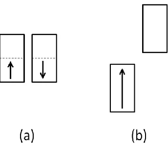
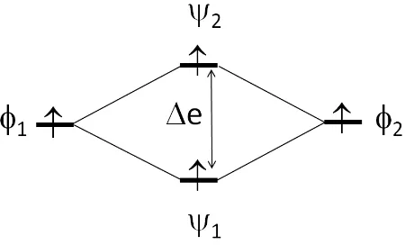
Fig. 2.1 Two electronic states that a system with a half-filled band can have: (a) Non-magnetic metallic state, in which both the up-spin and down-spin states are half-filled. (b) Magnetic insulating state, in which the up-spin band is completely filled, but the down-spin band, separated from the up-spin band by a band gap, is empty...22 Fig. 2.2 Split patterns of the up-spin and down-spin levels ( and , respectively) for the two extreme cases of spin arrangements for a 1D chain with one orbital per site: (a) FM state in which all sites have up-spins. (b) AFM state in which up-spin and down-spin sites alternate. Only two adjacent spin sites of the chain are shown for simplicity...23 Fig. 2.3 Orbital interaction between two spin sites described by the magnetic orbitals ϕ1 and
ϕ2 leading to the dimer levels ψ1 and ψ2 separated by the energy gap ∆e...24
Fig. 2.4 Weak JT distortion of a MO6 octahedron with (t2g)1 configuration leading to a
distorted MO6 octahedron with C3-rotational symmetry. This distortion splits the t2g level into
the pattern of 1a < 1e pattern, where the 1a level is described by the z2 orbital, when the local z-axis is taken along the C3-rotational axis...25
Fig. 2.5 Energies of the AFM, the unrelaxed FM and the relaxed FM states of a 2D square-lattice antiferromagnet described by the nearest-neighbor AFM spin exchange J (< 0). The relaxed FM state is described by a new nearest-neighbor spin exchange J for which J < J
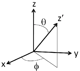
occurs when the spins are collinear. (b) Compromised non-collinear spin arrangement that minimizes the total spin exchange interactions...27 Fig. 2.7 Two coordinate systems used to describe the spin-orbit coupling HˆSOCLˆSˆ , where the spin z-axis (i.e., the preferred spin direction) is defined in terms of the angles (θ, ϕ) with respect to the Cartesian coordinate system describing the orbital angular momentum ...28 Fig. 2.8 (a) Two degenerate electron configurations of (Me3Si)3C-Fe-C(SiMe3)3 containing a
high-spin Fe2+ (d6) ion in the linear two-coordinate site. (b) Correspondence between the Cartesian and the spherical-harmonics representations for the split d-states of the linear-two coordinate Fe2+ (d6) ion...29 Fig. 3.1 (a) Projection view of the crystal structure of FeTe3O5X (X= Cl, Br) along b-axis,
where the blue, yellow, red and green spheres represent Fe3+, Te4+, O2- and X- ions, respectively. (b) An Fe-Te-O slab showing how the Fe2O8 dimer units (blue polyhedra) are
isolated from each other by the Te (grey) and O (red) atoms. The lone pair on Te4+ is marked
as a black circle...35 Fig. 3.2 Structures of the Fe2O8 dimer units in (a) FeTe3O7Cl (1) and (b) FeTe3O7Br (2)
...36 Fig. 3.3 Magnetic susceptibilities of FeTe3O7X (X = Cl, Br) measured with a field of 0.1 T.
The solid (red) lines are fits to the susceptibility of a spin dimer of Fe3+ (S = 5/2) cations
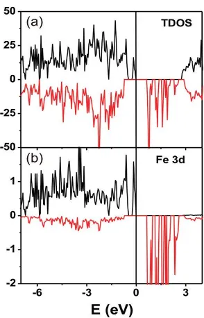
Fig. 3.4 Spin polarized electronic density of states (states/electron FU) of FeTe3O7Cl in the
FM configuration (see Fig. 12). (a) Total density of states. (b) Projected density of states of the Fe d electrons...38 Fig. 3.5 Definition of the three spin exchange parameters J1 (intradimer), J2, and J3 (both
interdimer) in FeTe3O7X (X = Cl, Br)...39
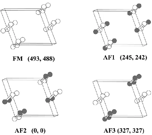
Fig. 3.6 Four ordered spin states FM, AF1, AF2, and AF3 in a (a, 2b, c) supercell employed to extract the values of J1, J2, and J3, where only the Fe atoms are shown for simplicity. The
up-spin and down-spin Fe3+ sites are represented by spheres of different colors. The numbers in parentheses give the relative energies (in meV) obtained from the GGA calculations with for 1 and 2, respectively...40 Fig. 4.1 Perspective view of the crystal structure of Ag2ZnZr2F14. The orange, green, blue
and grey represent silver, zirconium, zinc and fluorine atoms, respectively. The AgF4 units
are highlighted (in grey)………...46 Fig 4.2 Two-leg ladders of Ag2+ ions resulting from Ag2F7 dimers. The dotted lines running
along the b-axis represent the short F…F contacts (2.275 Å) between Ag2F7 dimers
...47 Fig. 4.3 Temperature dependence of the inverse molar susceptibility of Ag2ZnZr2F14 at a
magnetic field of 1T. The transition at around 163K is caused by a small amount of AgF2 in
the sample...48 Fig. 4.4 (a) Intra-ladder spin and inter-ladder spin exchange (J1 J3) Ag2ZnZr2F14, where the
Fig. 5.1 Perspective views of the LiNaCo[PO4]F structure (a) with and (b) without the
phosphorus and alkali metal atoms...57 Fig. 5.2 (a) Magnetic susceptibility vs. Temperature and the corresponding -1 vs. T plots of LiNaCo[PO4]Fmeasured with the applied field H = 10 kOe. (b) Heat capacities Cp(T) of
LiNaCo[PO4]F. The inset displays Cp/T in the region of the phase transition at 10.2(5) K
...58 Fig. 5.3 The magnetic structure of LiNaCo[PO4]F at 3K. The components of the moment
along x, y, and z axes are 2.13(2), 0, and 0.87(2) B, respectively. The total moment is
2.30(2) B, and the angle between the moment direction and ab-plane is 22.2°...59
Fig. 5.4 (a, b) Definitions of the spin exchange paths J1, J2, J3, J1', J2', and J3'. The Co1 and
Co2 atoms are indicated as empty and filled circles, respectively. The numbers 1, 2, 3, 1', 2' and 3' refer to the spin exchanges J1, J2, J3, J1', J2', and J3', respectively. (c) Ordered spin
arrangements of the Co1 and Co2 spin sites used to extract the values of J1, J2, J3, J1', J2', and
J3' by GGA+U calculations. The positions of the Co1FO3 and Co2FO3 chains are identical
Fig. 6.2 (a) Intra-layer spin exchange paths J1 – J4. (b) Inter-layer spin exchange paths Jc – Jc'''. The number 1 – 4 refer to J1 – J4, respectively, and the symbols c - c''' to Jc – Jc''', respectively
...71 Fig. 6.3 Total and projected density of state (DOS) plots of (a) experimental and (b) optimized structure...72 Fig. 6.4 Eight spin ordered states from FM – AF7 for(2a, b, 2c) supercell...73 Fig. 6.5 (a) Neutron powder diffraction patterns in Bi3Mn4O12(NO3) E = 1.7 meV at H = 0 and 10 T and at T = 3 K. At 10 T the broad magnetic peak is reduced and sharp magnetic peaks appear. (b) Magnetic structure in the magnetic field-induced phase. The Mn4+ ions in a 2×2×2 supercell are shown. The magnetic moments lie in the ab plane, although the direction
of the magnetic moments in the plane cannot be determined uniquely. Magnetic interactions
J1, J2, and Jc are also shown...74 Fig. 7.1 (a) Projection along the [001] direction of the trippkeite crystal structure. The Cu2+ atoms are represented by the large (green) spheres, the oxygen atoms by small (red) spheres, and the As atoms by (gray) medium spheres. (b) A corrugated chain of trans-edge connected CuO6 octahedra highlighting the twisted basal planes of the octahedra in CuAs2O4, which
lead to a corrugation of the CuO2 ribbon chains...84
Fig. 7.2 Reciprocal magnetic susceptibility of a polycrystalline CuAs2O4 sample measured in
Fig. 7.3 Three order spin states of CuAs2O4 used to determine the values of Jnn (≡J1) and Jnnn
(≡J2) by DFT+U calculations. Only the Cu sites are shown for simplicity. The unfilled and
filled circles represent up-spin and down-spin Cu2+ sites, respectively...86 Fig. 7.4 The ratio of the NN to NNN spin exchange constants of CuAs2O4 calculated from
the DFT+U calculations as a function of Ueff . The plot displays the dominance of the FM Jnn
term over the AFM Jnnn term...87
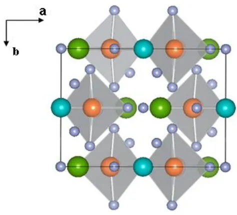
Fig. 8.1 (a) Projection view of ACo2V2O8 (A = Sr, Ba, Pb) on the ab-plane. The octahedra, tetrahedra, large ball and small ball represent CoO6, VO4, A, and O, respectively. The circle shows the Co4V4O16 cluster of a unit cell. (b) Perspective view of the Co2+ arrangements along the c-direction. (c) Projection view of ACo2V2O8 on the bc-plane...94 Fig. 8.2 Temperature variation of magnetization for (a) SrCo2V2O8 and (b) BaCo2V2O8 in an applied magnetic field of 5 KOe. The inset shows a zoomed-in view in 2 – 30 K range
...95 Fig. 8.3 Specific heats of SrCo2V2O8 and BaCo2V2O8 measured in zero magnetic field
...96 Fig. 8.4 Split pattern of the d-states of a high-spin Co2+ ion in an axially-compressed CoO6
octahedron with the C4-rotational symmetry...97
Fig. 8.5 PDOS plots obtained for the Co 3d states of BaCo2V2O8 from DFT+U (U = 2, 4, 6
eV) calculations for the FM state...98 Fig. 8.6 PDOS plots obtained for the Co 3d states of PbCo2V2O8 from DFT+U (U = 2, 4, 6
Fig. 8.7 PDOS plots obtained for the Co 3d states of SrCo2V2O8 from DFT+U (U = 2, 4, 6
eV) calculations for the FM state………100 Fig. 9.1 (a) A perspective view of the crystal structure of CuCl2·2H2O (blue circle: Cu,
yellow circle: Cl, red circle: O, white circle: H). (b) The magnetic structure of CuCl2·2H2O,
where the filled and unfilled circles represent up-spin and down-spin Cu2+ sites, respectively. (c) The local coordinate system chosen for an isolated CuCl2(OH2)2 complex with the
crystal-field split Cu 3d states. (d) The PDOS plots calculated for the Cu 3d states of CuCl2·2H2O using the “isolated Cu2+ ion” model...116
Fig. 9.2 (a) A schematic view of a CuL2 (L = O, Cl, Br) ribbon chain found in LiCuVO4,
CuCl2 and CuBr2. (b) A schematic view of the spin-spiral arrangement in the CuL2
ribbon chain, for the case when the spin-spiral plane is the xy-plane. (c) An “isolated Cu2+ ion” model, in which a chain of Cu2+ ions is replaced with a (Cu2+-Mg2+-Mg2+-Mg2+) chain.
i(d) A schematic view of the collinear arrangement of Cu2+ spins in the CuL2 ribbon
1. Introduction
We have investigated the structure-property relationships in a number of magnetic oxides containing transition-metal magnetic ions Cu2+, Fe2+, Ag2+, Co2+ and Mn4+ on the basis of DFT electronic structure calculations. They include FeTe3O7X (X = Cl, Br), Ag2ZnZr2F14, LiNaCo[PO4]F, CuAs2O4, Bi3Mn4O12(NO3), ACo2V2O8 (A = Ba, Pb, Sr) and
several other oxides of Cu2+ ions. In this document, we report results of our investigations on these magnetic materials. Our DFT studies on FeTe3O7X (X = Cl, Br), Ag2ZnZr2F14,
LiNaCo[PO4]F, Mn[N(CN)2]2 and CuAs2O4 have been published. Results of our DFT
calculations concerning the origin of the magnetic anisotropy of spin-half Cu2+ ions have been written up for publication, and our studies on Bi3Mn4O12(NO3) and ACo2V2O8 (A = Ba, Pb, Sr) have just been completed. This dissertation is organized as follows: Section 2 provides a brief review on the general concepts necessary for understanding magnetic solids and describes the computational methods employed in this study. Results of our studies on FeTe3O7X (X = Cl, Br), Ag2ZnZr2F14, LiNaCo[PO4]F, CuAs2O4, several magnetic oxides of
Cu2+ ions, Bi3Mn4O12(NO3) and ACo2V2O8 (A = Ba, Pb, Sr) are presented in Sections 3 – 9.
2. Theoretical considerations1
In magnetic oxides composed of transition-metal ions Mn+ in oxidation state +n, the transition-metal elements form MOm polyhedra with their first-coordinate O atoms, and these
polyhedra are interlinked to make M-O-M and/or M-O…O-M connections between adjacent Mn+ ions. The unpaired spins of the Mn+ ions are accommodated in the d-levels of the MOm
those M-O-M and/or through M-O…O-M paths to which the magnetic orbitals have non-zero orbital contributions. Thus, the effective interaction between adjacent Mn+ ions increases by
increasing the overlap of the M nd orbitals with the O 2p orbitals in the M-O bonds. In general, the nd orbital of M in zero oxidation state shows spatial extension that increases in the order 3d < 4d < 5d, so the widths of the d-block bands should increase in the order 3d < 4d < 5d. Furthermore, with increasing the spatial extension of the M nd orbital, the electron correlation associated with the M nd orbitals should decrease thereby decreasing their on-site repulsion U in the order 3d > 4d > 5d. Consequently, magnetic insulators are more frequently found for 3d metal oxides than for 4d/5d metal oxides. Nevertheless, a number of 4d/5d metal oxides become magnetic insulators when their d-orbitals are strongly contracted, which occurs when their Mn+ ions are in high oxidation state. In this section we will briefly survey various conceptual, theoretical and computational issues that are needed in analyzing the structure-property relationships of transition-metal magnetic oxides on the basis of electronic band structure calculations and orbital-interaction analysis.
2.1. Magnetic insulating versus metallic state1
consists of up-spin and down-spin subbands degenerate in energy (Fig. 2.1a). Consequently, any solid with partially filled bands has no energy gap between the highest-occupied and the lowest-unoccupied band levels, and is therefore predicted to be a non-magnetic metal. However, a solid with partially-filled bands can be a magnetic insulator,2,3 in which up-spin and down-spin subbands differ in energy such that an energy gap (i.e., a band gap) occurs between the highest-occupied and the lowest-unoccupied subbands (Fig. 2.1b). It should be recalled that the presence of partially-filled bands is only a necessary condition for a system to become either a metal or a magnetic insulator. The failure of the non-spin-polarized DFT method in describing magnetic insulators is partly remedied by employing the spin-polarized DFT method, which allows up-spin and down-spin subbands to have different spatial orbitals and hence differ in energy. For most magnetic insulators, however, this splitting of up-spin and down-spin subbands given by the spin-polarized DFT method is not large enough to produce a band gap. Currently, this deficiency of the spin-polarized DFT method is empirically corrected by using the spin-polarized DFT+U method,4 which adds on-site repulsion U on the magnetic transition-metal atoms to enhance the spin polarization of their nd orbitals (Fig. 2.2).
DFT+U method, currently employed to describe magnetic insulating states, is empirical because U is an empirical parameter. In describing a magnetic insulator by this method, therefore, it is important to first establish a range of U values producing a band gap and then explore their chemistry and physics on the basis of consistent trends resulting from such U parameters.
2.2. Spin exchange interaction1
In analyzing experimental results (e.g., magnetic susceptibility, specific heat and spin wave dispersion) in terms of the spin Hamiltonian
spin ij i j i j
ˆ ˆ
ˆH J S S
, (1)the spin exchange parameters Jij are numerical fitting parameters needed to reproduce these
results. Consequently, the signs and magnitudes of these “experimental” Jij parameters
depend on the spin lattice chosen for the spin Hamiltonian, and two different sets of Jij values
may provide an equally acceptable fitting.5 It is essential to examine the electronic structure of a magnetic solid to obtain a relevant spin lattice.
2.2.a. Qualitative aspect1
For a spin dimer made up of two equivalent spin sites with one electron per site, suppose that the two spin sites 1 and 2 are described by the magnetic orbitals ϕ1 and ϕ2,
respectively. The interaction between ϕ1 and ϕ2 leads to the molecular levels ψ1 and ψ2 of the
singlet and triplet states with the energy difference between them as E = ES – ET. This
energy spectrum is reproduced by the spin Hamiltonian,
ˆHspin JS Sˆ ˆ1 2, (2)
if J = E. When the spin sites 1 and 2 are described by the magnetic orbitals ϕ1 and ϕ2,
respectively, then the J parameter is written as 5,6
2
F AF 12 eff
( e)
J J J 2K
U
(3)
The FM component JF is proportional to the exchange integral K12, which increases with
increasing the overlap density ϕ1ϕ2. The AFM component JAF is proportional to (e)2 and is
inversely proportional to the effective on-site repulsion Ueff. Since e is proportional to the
overlap integral 1 2 , the magnitude of JAF increases with increasing 1 2 . Therefore, a
spin exchange becomes AFM when the overlap integral 1 2 is large and the overlap
density ϕ1ϕ2 is small, but becomes FM when the overlap integral 1 2 is small and the
overlap density ϕ1ϕ2 is large.
In magnetic solids made up of MOm polyhedra, the interaction between spin sites,
say, M1 and M2, takes place through the superexchange M1-O-M2 path or through the super-superexchange M1-O…O-M2 path. As mentioned earlier, the magnetic orbitals of MOm have the M nd orbitals combined out-of-phase with the O 2p orbitals. Therefore, the
overlap density ϕ1ϕ2 and the overlap integral 1 2 between the magnetic orbitals ϕ1 and ϕ2
M1-O…O-M2 super-superexchange. Namely, the sign and magnitude of a spin exchange interaction between two spin sites is determined primarily by the tail parts (i.e., the O 2p orbitals) of their magnetic orbitals lying only in the region between them.5 This is the reason why a spin Hamiltonians defined in terms of only pair-wise spin exchange interactions can provide a good description for the excitation energy spectrum of a given magnetic solid.
It is important to recall that, for magnetic solids consisting of both M-O-M superexchange and M-O…O-M super-superexchange paths, spin exchange interactions that occur through super-superexchange paths with short O…O contact distances (i.e., around the van der Waals distance and shorter) can be much stronger than those through M-O-M paths, and hence should not be neglected.5 In particular, for a M1-O…O-M2 super-superexchange path in which the O…O contact is linked through a d0 cation Mn+ (e.g., V5+, Mo6+ and W6+)
to form an O…M…O linkage, the empty d-orbitals of M can overlap effectively with the
magnetic orbitals of both M1 and M2 and hence dramatically enhance or reduce the spin exchange interaction between M1 and M2,7,8 depending on the symmetry of the linkage. Even when the O…O contact is linked through an alkaline earth cation A2+ (e.g., Sr2+) to
form an O…A…O linkage, whether the M1-O…A…O-M2 spin exchange is FM or AFM can be influenced by the virtual d-orbitals of A2+.9
2.2.b. Quantitative evaluation by energy-mapping1
associated spin exchange parameters J1, J2, …, JN, the energy-mapping method determines
the electronic energies Eelec of the N+1 ordered spin states (i.e., broken-symmetry states) (i =
1, 2, …, N+1) by DFT+U calculations so as to obtain N relative energies Eelec. For these
calculations, it is important to make sure that all ordered-spin states are magnetic insulating states. The total spin exchange energies Espin of the N+1 ordered spin states can be
determined by using the spin Hamiltonian ˆH (Eq. 1) defined in terms of Jspin 1, J2, …, JN
(namely, Jij = J1 – JN) so as to determine N relative energies Espin expressed in terms of N
parameters J1 – JN. In writing the expression of the total spin exchange energy for an ordered
spin state in terms of J1 – JN, we employ the energy expressions for the FM and AFM
arrangements of a general spin dimer whose spin sites i and j possess Ni and Nj unpaired
spins (hence, spins Si = Ni/2 and Sj = Nj/2), respectively.10 Given Jij as the spin exchange
parameter for this spin dimer, the FM and AFM arrangements of this spin dimer lead to the spin exchange energies
FM arrangement: N N J / 4i j ij S S Ji j ij
AFM arrangement: N N J / 4i j ij S S Ji j ij (4)
Thus, the total spin exchange energy of an ordered spin arrangement is obtained by summing up all pair-wise interactions. Then, by mapping the N relative energies Eelec onto the N
relative energies Espin, we obtain the values of J1 – JN. In determining N spin exchanges J1,
J2, …, JN, one may employ more than N+1 ordered spin states, hence obtaining more than N
relative energies Eelec and Espin for the mapping.5 In this case, the N parameters J1 – JN can
strengths of spin exchange parameters Jij involving spin sites with different numbers of
unpaired spins, it is necessary to use the effective spin exchange parameters Jeffij that
incorporate the values of the associated spins Si and Sj, namely, eff
ij i j ij
J S S J (5)
The energy-mapping method described above is objective in that, once a set of spin exchange paths is chosen for a magnetic solid, it does not presume whether the associated spin exchange parameters should be FM or AFM. This method simply maps the electronic energy spectrum of DFT+U calculations onto the energy spectrum of the spin Hamiltonian defined by a set of spin exchange parameters. However, the values of the resulting spin exchange parameters depend on what set of exchange paths one selects. In identifying the spin lattice appropriate for a magnetic solid under consideration, therefore, energy-mapping analysis should be carried out for a set of spin exchange paths large enough to include all important ones. In particular, for magnetic solids consisting of both M-O-M and M-O…O-M spin exchange paths, those M-O…O-M paths with short O…O contact distances should not be omitted in the energy-mapping analysis.
When a set of spin exchange parameters are evaluated by performing DFT+U calculations as a function of U, it is generally found that the values of AFM spin exchanges become smaller in magnitude with increasing U.11c,12a,13 For magnetic systems with well localized electrons, for which increasing U does not increase the moment on each spin site, this is expected because the AFM component JAF of a spin exchange decreases in strength
of spin exchange parameters calculated for a magnetic solid from DFT+U calculations with various U values, the relative strengths of the spin exchange parameters are not strongly affected by U, hence predicting an identical spin lattice for the magnetic system. To check the proper range of U values, one may calculate the Curie-Weiss temperature θ in the mean-field approximation, which is given by 14
i i i B S(S 1) z J 3k
, (6)where the summation runs over all nearest neighbors of a given spin site, zi is the number of
nearest neighbors connected by the spin exchange parameter Ji, and S is the spin quantum
number of each spin site.
2.2.c. Dependence of spin exchange parameters on crystal structure1
An interesting situation occurs when a solid with AFM ground state is forced to adopt the FM state under strong magnetic field. As an example, consider a 2D square antiferromagnet described by the nearest-neighbor AFM spin exchange J. Then, the energy per site of the AFM state is given by 2J, and that of the FM state by −2J (Fig. 2.4). When forced to be in the FM state under magnetic field, this antiferromagnet can lower the energy of the FM state by relaxing its crystal/electronic structure such that the spin exchange is weakened from J to a new value J (namely, J < J) (Fig. 2.5).15 Then, the energy of the FM
state will be lowered from −2J to −2J. For an AFM spin exchange, J −t2 because e t.
2.2.d. Spin frustration1
The spin Hamiltonian, Eq. 1, expresses the total energy of a magnetic system as a sum of pair-wise spin exchange interactions. Each individual term J S Sij iˆ ˆ j forces the spins
and to be collinear; the energy-lowering is maximum when the two spins are
antiparallel and parallel if Jij is AFM (Jij < 0) and FM (Jij > 0), respectively. A collinear spin
arrangement is energetically unfavorable for a certain spin lattice composed of several different spin exchange paths, if the spin lattice generates either triangular or linear spin frustration. An archetypal example of triangular spin frustration is found for a triangular lattice made up of nearest-neighbor AFM spin exchange paths (Fig. 2.6a),16,17 and the minimum-energy spin configuration for such a triangle is given by a non-collinear configuration (Fig. 2.6b).
It should be noted that the non-collinearity dictated by spin frustration deals only with the relative spin arrangement, and has nothing to say about the preferred spin orientation in space. What determines the preferred spin orientation in space is spin-orbit coupling (SOC) 18 and/or magnetic dipole-dipole (MDD) 19 interaction, which will be discussed in the next section. The electronic structures of collinear magnetic states are described by non-collinear spin-polarized DFT+U calculations.
For an AFM system with spin frustration, its Curie-Weiss temperature θ is large in magnitude compared with its Néel temperature TN (i.e., the 3D AFM ordering temperature).
Some extent of spin frustration exists in most AFM systems, so that TN is typically lower
regarded as spin frustrated.16 For a magnetic system with high degree of spin frustration, its magnetic ground state is highly degenerate because a large number of different spin arrangements have the same energy. On lowering the temperature, such a system tends to lower its energy by undergoing a slight structural distortion and hence reducing the extent of spin frustration.
2.3 Spin-orbit coupling, uniaxial magnetism and magnetic dipole-dipole interactions
2.3.1. Spin-orbit coupling and spin orientation in space1
The SOC of a magnetic ion is discussed in terms of the Hamiltonian
SOC ˆ
ˆ ˆ
H L S, (7)
where λ is the SOC constant of the ion, and ˆL and ˆS are the orbital and spin angular momentum operators of the magnetic ion, respectively. For a transition-metal ion with lower than d5 electron count, λ > 0, so the orbital and spin moments couple antiparallel to each
To understand how SOC works, it is necessary to consider the general expression of ˆ
ˆL S in which the preferred spin direction z is allowed to differ from the orbital z-direction,
that is,18,20
2 sin e Lˆ 2 cos e Lˆ sin Lˆ Sˆ 2 1 2 cos e Lˆ 2 sin e Lˆ sin Lˆ Sˆ 2 1 sin e Lˆ 2 1 sin e Lˆ 2 1 cos Lˆ Sˆ Sˆ Lˆ 2 i 2 i z 2 i 2 i z i i z z
, (8)
where the preferred orientation of the spin z axis is defined by the polar angles θ and ϕ of the
orbital Cartesian coordinate system (x, y, z) (Fig. 2.7). For a magnetic solid made up of MOm
polyhedra, the SOC allows the up-spin or down-spin occupied d-levels i (ψo and ψo,
respectively) to interact with the up-spin or down-spin unoccupied d-levels j (ψu and ψu,
respectively) via the matrix element i Hˆsoc j . The energy lowering associated with
soc
ˆ
i H j depends on the polar angles θ and ϕ, so that the SOC determines the preferred
direction of the spin (more precisely speaking, the preferred direction of the moment ) at
the magnetic ion. The moment is related to the spin and orbital momenta (S and L, respectively) as / ) S g L
( B
, (9)
where g is the electron g-factor (i.e., 2.0023) and μB is the Bohr magneton. In addition, it
should be noted that the SOC can lift the d-level degeneracy determined from DFT+U calculations.
calculations, its total energy including SOC interactions should be calculated as a function of the spin direction.21 Then, the easy-axis direction is the spin direction with the lowest total
energy. Experimentally, neutron diffraction refinements at a very low temperature provide information about the magnitudes and orientations of the moments at the spin sites of a magnetic solid.
2.3.2. Uniaxial magnetism1
A magnetic system with uniaxial magnetism has a nonzero magnetic moment only along one direction in space.22,23 The consideration of the crystal field and SOC effects shows that, for a system with transition-metal magnetic ions to have uniaxial magnetic properties, the following three conditions should be satisfied.22
(a) The site symmetry of the transition-metal ion should have an n-fold rotational symmetry with n ≥ 3, so that its d-levels have degenerate sets, i.e., {x2-y2, xy} and {xz, yz} with the z-axis taken along the rotational z-axis.
(b) The d-electron count of the transition-metal ion should be such that one of the two degenerate d-states is occupied by three electrons, and hence the ground state of the ion is described by two degenerate electronic configurations with nonzero orbital angular momentum. As a representative example, Fig. 2.8 shows the two degenerate electronic configurations of (Me3Si)3C-Fe-C(SiMe3)3, in which the C-Fe-C frame is linear and the Fe
atom exists as a high-spin Fe2+ (d6) ion.
Then, in the ground state arising from the SOC interaction , and become parallel to each other so that the J = L + S value is large, and the ΔJz values becomes greater than 1
(note that Jz = ±J). It is important to note that the electronic structure required for uniaxial
magnetism is also the condition leading to Jahn-Teller (JT) instability. The latter refers to the tendency of a system with degenerate electronic states to undergo a geometrical distortion that removes the degeneracy of the electronic state.24 Thus, the JT distortion of a system with uniaxial magnetism will remove the n-fold (n ≥ 3) rotational symmetry that is responsible for the uniaxial magnetism to begin with. In other words, uniaxial magnetism and JT instability are incompatible, unless JT distortion is prevented by steric hindrance as in (Me3Si)3C-Fe-
C(SiMe3)3.23 It is of interest to examine how these opposing factors compete in systems with
no strong steric hindrance.
2.3.3. Magnetic dipole-dipole interactions1
The spin exchange, SOC and DM interactions are short-range interactions, whereas the MDD interaction is a long-range interaction. The MDD interaction is weak, being of the order of 0.1 meV for two spin-1/2 ions separated by 2 Å, but is responsible for the formation of various FM domains in an FM material. Given that two spins located at sites i and j are described by the distance rij with the unit vector along the distance, the MDD interaction
is described by 19
where a0 is the Bohr radius (0.529177 Å), and (gμB)2/(a0)3 = 0.725 meV.
2.4. Computational methods 2.4.1. Density functional theory
In our work, we have applied Density functional theory (DFT) to analyze the electronic structures. In quantum mechanics,27 the electronic structure of a many-electron system is described by the Schrödinger equation
, (11)
where Ĥ is Hamiltonian. In the Born-Oppenheimer approximation, the Hamiltonian is written as,27 i 2 2 2 r
i e j i j i j i i
1 e Ze
ˆH(r,R)
2m 2 r r r R
, (12)which describe the electronic kinetic energy, electron-electron repulsion and electron-nuclear attraction. Describing an interacting system of electrons via its electron density ρ instead of calculating its wave function is the main idea of DFT. Hohenberg and Kohn 28 proved that for a system with nondegenerate ground state, the ground-state energy E0 is uniquely
determined by the ground-state electron density ρ0(x,y,z). The ground-state electronic energy
E0 is a function of ρ0, namely, E0 = E0[ρ0]. According to the Hohenberg-Kohn theorem, the
ground-state electronic wave function ψ0 of a many-electron system is an eigenfunction of
the purely electronic Hamiltonian Ĥ,
2 2
2
i ext i
i i j i j i j
1 e
ˆH v (r )
2m 2 r r
, (13)2.4.2. Exchange-correlation energy functionals
The exact expression of the exchange-correlation functional is not known except for the free electron gas, which is the major problem with DFT. However, one can get approximate expressions that permit the calculation of certain physical quantities quite accurately. In this article, the generalized-gradient approximation (GGA) 28 of Perdew, Burke and Ernzerhof 29 were used as the exchange-correlation functionals. The GGA depends on the local density and its gradient as,28
, (14)
2.4.3. Program package employed and on-site repulsion U
In our calculations of the electronic structures for solid-state magnetic oxides, we employed the frozen-core projector augmented wave 30 method encoded in the Vienna Ab-initio Simulation Package (VASP).31 For magnetic solids containing typically 3d transition
References
1. Xiang, H. J.; Lee, C.; Koo, H. –J.; Gong X. G.; Whangbo, M. –H. Dalton Trans., 2013, 42, 823.
2. Mott, N. F., Metal-Insulator Transitions, 2nd ed.; Taylor & Francis: London, 1990. 3. Whangbo, M. -H., J. Chem. Phys. 1979, 70, 4963.
4. Dudarev, S. L.; Botton, G. A.; Savrasov, S. Y.; Humphreys, C. J.; Sutton, A. P. Phys. Rev. B 1998, 57, 1505.
5. Whangbo, M.-H.; Koo, H.-J.; Dai, D., J. Solid State Chem. 2003, 176, 417. 6. Hay, P. J.; Thibeault, J. C.; Hoffmann, R., J. Am. Chem. Soc. 1975, 97, 4884. 7. Koo, H. -J.; Whangbo, M. -H., Inorg. Chem. 2006, 45, 4440.
8. (a) Dai, D.; Koo, H. -J.; Whangbo, M. -H., Inorg. Chem. 2004, 43, 4026. (b) Koo, H. -J.; Lee, C.; Whangbo, M.-H.; Mclntyre, G. J.; Kremer, R. K., Inorg. Chem., in press.
9. Tian, C.; Wibowo, A. C.; zur Loye, H. -C.; Whangbo, M. –H., Inorg. Chem., in press. 10. (a) Dai, D.; Whangbo, M.-H. J. Chem. Phys. 2001, 114, 2887. (b) Dai, D.; Whangbo,
M.-H. J. Chem. Phys. 2003, 118, 29.
11. (a) Miura,Y.; Hirai, R.; Kobayashi, Y.; Sato, M., J. Phys. Soc. Jpn. 2006, 75, 84707. (b) Derakhshan, S.; Cuthbert, H. L.; Greedan, J. E.; Rahman, B.; Saha-Dasgupta, T., Phy. Rev. B 2007, 76, 104403. (c) Koo, H. –J.; and Whangbo, M. –H., Inorg. Chem. 2008, 47,
128. (d) Sakurai, H.; Yoshimura, K.; Kosuge, K.; Tsujii, N.; Abe, H.; Kitazawa, H.; Kido, G.; Michor, H.; Hilscher, G., J. Phys. Soc. Jpn. 2002, 71, 1161.
T.; Kaburagi, M., J. Phys. Condens. Matter 2003, 15, 5979. (c) Koo, H. -J.; Whangbo, M. -H., Inorg. Chem. 2008, 47, 4779.
13. Xiang, H. J.; Lee, C.; Whangbo, M.-H. Phys. Rev. B 2007, 76, 220411(R). 14. Smart, J. S.; Effective Field Theory of Magnetism: Saunders, Philadelphia, 1966. 15. Musfeldt, J. L.; Vergara, L. I.; Brinzari, T. V.; Lee, C.; Tung, L. C.; Kang, J.; Wang,
Y. J.; Schlueter, J. A.; Manson, J. L.; Whangbo, M. -H., Phys. Rev. Lett. 2009, 103, 157301.
16. Greedan, J. E., J. Mater. Chem. 2001, 11, 37, and the references cited therein. 17. Dai, D.; Whangbo, M.-H., J. Chem. Phys. 2004, 121, 672.
18. Dai, D.; Xiang, H. J.; Whangbo, M. -H., J. Comput. Chem. 2008, 29, 2187. 19. Koo, H.-J. X., H.; Lee, C.; Whangbo, M-H., Inorg. Chem. 2009, 48, 9051. 20. Wang, X.; Wu, R.; Wang, D.-S.; Freeman, A. J., Phys. Rev. B 1996, 54, 61.
21. Kunes 2001: Kuneš, J.; Novák, P.; Diviš, M.; Oppeneer, P. M. Phys Rev B 2001, 63, 205111.
22. Dai, D.; Xiang, H. J.; Whangbo, M. -H., J. Comput. Chem. 2008, 29, 2187. 23. Dai, D.; Whangbo, M.-H., Inorg. Chem. 2005, 44, 4407.
24. Jahn, H. A.; Teller, E. Proc. Roy. Soc. A 1937, 161, 220. 25. Bramwell, S. T.; Gingras, M. J. P., Science 2001, 294, 1495.
26. (a) Ewald, P. P., Ann. Phys. 1921, 64, 253. (b) Darden, T.; York, D.; Pedersen, L., J. Chem. Phys. 1993, 98, 10089.. (c) Wang, H.; Dommert, F.; Holm, C., J. Chem. Phys.
2010, 133, 034117.
28. Levine, I. N. Quantum Chemistry, Prentice-Hall, India, 2006.
29. Perdew, J. P.; Burke, K.; Ernzerhof, M., Generalized Gradient Approximation Made Simple. Phys. Rev. Lett. 1996, 77 (18), 3865.
30. Kresse, G.; Joubert, D., From ultrasoft pseudopotentials to the projector augmented- wave method. Phys. Rev. B: Condens. Matter 1999, 59 (3), 1758.
31. (a) Kresse, G.; Hafner, J., Ab initio molecular dynamics for liquid metals. Phys. Rev. B:Condens. Matter 1993, 47 (1), 558. (b) Kresse, G.; Furthmüller, J., Efficiency of
abinitio total energy calculations for metals and semiconductors using a plane-wave
basis set. Comput. Mater. Sci. 1996, 6 (1), 15. (c) Kresse, G.; Furthmüller, J., Efficient
iterative schemes for ab initio total-energy calculations using a plane-wave basis
set.Phys. Rev. B: Condens. Matter 1996, 54 (16), 11169.
32. Anisimov, V. I.; Aryasetiawan, F.; Lichtenstein, A. I. J. Phys.: Condensed Matter 1997, 9, 767.
33. Dudarev, S. L.; Botton, G. A.; Savrasov, S. Y.; Humphreys, C. J.; Sutton, A. P. Phys. Rev. B 1998, 57, 1505.
34. Dudarev, S. L.; Botton, G. A.; Savrasov, S. Y.; Humphreys, C. J.; Sutton, A. P., Electronenergy-loss spectra and the structural stability of nickel oxide: An LSDA+U
study. Phys.Rev. B: Condens. Matter 1998, 57 (3), 1505.
Fig. 2.3 Orbital interaction between two spin sites described by the magnetic orbitals ϕ1 and
Fig. 2.4 Weak JT distortion of a MO6 octahedron with (t2g)1 configuration leading to a
distorted MO6 octahedron with C3-rotational symmetry. This distortion splits the t2g level into
(a) (b)
Fig. 2.8 (a) Two degenerate electron configurations of (Me3Si)3C-Fe-C(SiMe3)3 containing a
3. Spin exchange interactions and magnetic structure of FeTe3O7X (X = Cl, Br)1
The two isostructural compounds FeTe3O7Cl (1) and FeTe3O7Br (2) crystallize in the monoclinic system, space group P21/c. FeTe3O7X (X = Cl, Br) is made up of covalently
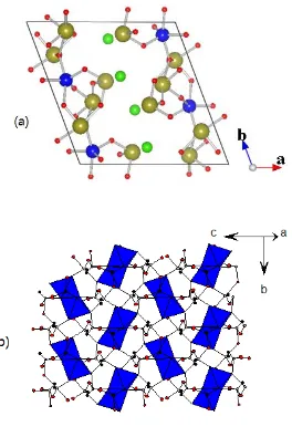
bonded Fe-Te-O slabs with halide ions located between them so that only weak van der Waal interactions are present between adjacent Fe-Te-O slabs. A projection view of the Fe-Te-O slabs and halide ions along the b-axis is shown in Fig. 3.1a. There is one kind of crystallographically unique Fe3+ cations forming distorted FeO
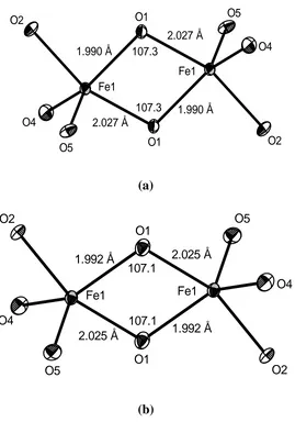
5 trigonal bipyramids, which
share their edges to form Fe2O8 dimer units (Fig. 3.2). In each Fe-Te-O slab the Fe2O8 dimers are well isolated by the Te-O framework made up of corner-sharing TeO4 and TeO3 units containing Te4+-cations (Fig. 3.1b). The halide ions are not considered as fully integrated into the covalent Fe-Te-O network but act more as counter anions as found in other oxohalides such as (TeO3)6Cl2 and Fe3(TeO3)3OCl.2,3
For 1 and 2 we consider three spin exchange interactions J1 – J3 defined in Fig. 3.5,
where J1 is the intra-dimer spin exchange while J2 and J3 are inter-dimer spin exchanges. To
evaluate these interactions, we determine the relative energies of the four ordered spin states, FM, AF1, AF2 and AF3, using a (a, 2b, c) supercell (Fig. 3.6). The relative energies of these states calculated by performing spin-polarized GGA calculations are also summarized in Fig. 3.6. To extract the values of J1 – J3, we express the total spin exchange interaction energies of
the four ordered spin states in terms of the spin Hamiltonian, ij i j
i j
ˆ ˆ
ˆH
J S S , where Jij =J1 – J3 is the spin exchange constant for the interaction between the spins ˆS and i ˆS at the j
sites i and j, respectively. By applying the energy expression obtained for spin dimers consisting of two spin sites with N unpaired spins (i.e., N = 5 for Fe3+), the total spin exchange energies, per supercell, i.e., per eight formula units (FUs), of the four ordered spin states are written as
) 4 / N )( J 16 J 8 J 4 ( E ) 4 / N )( J 16 J 8 J 4 ( E ) 4 / N )( J 8 J 4 ( E ) 4 / N )( J 16 J 8 J 4 ( E 2 3 2 1 3 AF 2 3 2 1 2 AF 2 2 1 1 AF 2 3 2 1 FM
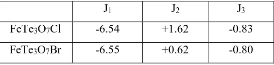
Then, by mapping the relative energies of the four ordered spin states determined from GGA calculations onto the corresponding relative energies determined from the above expressions, we obtain the values of J1 – J3 listed in Table 3.1. The antiferromagnetic intra-dimer
exchange J1 dominates. The inter-dimer spin exchanges are weak but are not negligible. This
the same, and so are the inter-dimer exchange J3. However, 1 and 2 differ mainly in the
inter-dimer exchange J2. We note that the calculated J1 values are greater than the experimental
values by a factor of approximately 4.5-7 In general, GGA calculations are known to overestimate spin exchange constants.
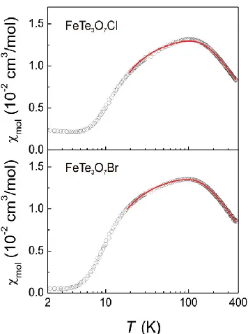
Experimentally, the magnetic properties of FeTe3O7X (X = Cl, Br) are well described
by an isolated antiferromagnetic spin dimer model with spin gaps of approximately 17.5 K and 15.8 K for X = Cl and Br, respectively.1 High-field magnetization experiments suggest
the presence of some inter-dimer interactions of the order of ~1 K.1 These observations are supported by the spin exchange interactions of FeTe3O7X (X = Cl, Br) obtained from our
References
1. Zhang, D.; Kremer, R.K.; Lemmens, P.; Choi, K-Y.; Liu, J.; Whangbo, M-H.; Berger, H.; Skourski, Y.; Johnsson, M. Inorg. Chem. 2011, 50, 12877-12885.
2. Becker, R.; Johnsson, M. J. Solid State Chem. 2007, 180, 1750-1758.
3. Zhang, D.; Johnsson, M.; Berger, H.; Kremer, R.K.; Wulferding, D.; Lemmens, P. Inorg. Chem. 2009, 48, 6599-6603.
4. Dudarev, S. L.; Botton, G. A.; Savrasov, S. Y.; Humphreys, C. J.; Sutton, A. P. Phys. Rev. B 1998, 57, 1505.
5. Dai, D.; Whangbo, M.-H. J. Chem. Phys. 2001, 114, 2887.
6. Dai, D.; Koo, H.-J.; Whangbo, M.-H. J. Solid State Chem. 2003, 175, 341.
Table 3.1. Spin exchange constants (in meV) of FeTe3O7Cl and FeTe3O7Cl obtained from
GGA calculations
J1 J2 J3
FeTe3O7Cl -6.54 +1.62 -0.83
Fig. 3.1 (a) Projection view of the crystal structure of FeTe3O5X (X= Cl, Br) along b-axis,
where the blue, yellow, red and green spheres represent Fe3+, Te4+, O2- and X- ions,
respectively. (b) An Fe-Te-O slab showing how the Fe2O8 dimer units (blue polyhedra) are
107.3 O5 O4 O2 2.027 Å 1.990 Å O1 2.027 Å Fe1 1.990 Å 107.3 Fe1 O1 O2 O4 O5 (a) O5 O4 O2
2.025 Å 1.992 Å
O1 2.025 Å 107.1 Fe1 1.992 Å 107.1 Fe1 O1 O2 O4 O5 (b)
Fig. 3.3 Magnetic susceptibilities of FeTe3O7X (X = Cl, Br) measured with a field of 0.1 T.
Fig. 3.4 Spin polarized electronic density of states (states/electron FU) of FeTe3O7Cl in the
Fig. 3.5 Definition of the three spin exchange parameters J1(intradimer), J2, and J3 (both
Fig. 3.6 Four ordered spin states FM, AF1, AF2, and AF3 in a (a, 2b, c) supercell employed to extract the values of J1, J2, and J3, where only the Fe atoms are shown for simplicity. The
up-spin and down-spin Fe3+ sites are represented by spheres of different colors. The numbers
4. Magnetic structure and spin exchange interactions of Ag2ZnZr2F141
Compounds containing Ag2+ (d9) ions are rare and have interesting magnetic
properties such as the strong antiferromagnetically coupled one-dimensional (1D) chain of Ag2+ ions in AgSO4,2 the two-dimensional (2D) ferromagnetic square net of Ag2+ ions in
Cs2AgF4.3 Ag2ZnZr2F14 was synthesized to study the magnetic properties of the discrete
Ag2F7 dimers.1 This deep blue-violet colored compound crystallizes in the space group C2/m
and each Ag2+ forms a square planar geometry with surrounding F atoms (Fig. 4.1). The
AgF4 units form Ag2F7 dimers by sharing a corner, which are connected by ZnF6 octahedra
and ZrF7 pentagonal bipyramids to provide the 3D framework ofAg2ZnZr2F14. The Ag2F7
dimers are running along b-axis and result in two-leg ladders of the Ag2+ ions as depicted in Fig. 4.2.
The magnetic susceptibility of Ag2ZnZr2F14 (Fig. 4.3) shows that at room temperature
more than ~95 % of the spins are antiferromagnetically coupled. The value of χmol at 300 K
under a field of 1 T is very small (i.e., ~0.9 10-4 cm-3·mol-1). Due to the thermal instability
of the compound, measurements of the magnetic susceptibility at higher temperatures cannot be performed. Consequently, no useful information can be gained from experiments as to what kind of an AFM spin lattice is responsible for the very weak magnetic of Ag2ZnZr2F14
at room temperature.
In order to understand the magnetic properties of Ag2ZnZr2F14, we determine the
three spin exchange interactions, namely, the rung exchange J1 and the leg exchange J2 as
well as the inter-ladder exchange J3 defined in Fig. 4.4a. To determine the values of J1 – J3,
c) supercell. The relative energies of these states per supercell, i.e., per eight formula units (FUs), calculated by performing GGA+U calculations are summarized in Table 4.1. In terms of the spin Hamiltonian, ij i j
j
i S
ˆ Sˆ J
Hˆ
, where Jij (= J1 – J3) is the spin exchangeconstant for the interaction between the sites i and j,4 the total spin exchange energies, per eight formula Fus, of the three ordered spin states are written as
1 2 3 4AF 1 2 3
AF 1 2
AF 1 2
AF 1 2 3
E 4J 8J 8J 1 4
E 4J 8J 1 4
E 4J 8J 1 4
E 4J 8J 8J 1 4
Thus, by mapping the relative energies of the four ordered spin states determined from GGA+U calculations onto the corresponding relative energies determined from the above expressions, we obtain the values of J1 – J3 listed in Table 4.2. Clearly, the rung exchange J1
dominates over the leg exchange J2 and the inter-ladder exchange J3 for all values U = 2 – 6
eV. To a first approximation, therefore, the magnetic properties of Ag2ZnZr2F14 can be
References
1. Tong, J.W.; Kraus, F.; Kӧhler, J.; Simon, A; Liu, J.; Whangbo, M-H. Z. Anorg. Allg. Chem. 2011, 637, 1118-1121.
2. a) P. J. Malinowski, M. Derzsi, Z. Mazej, Z. Jaglicic, B. Gawel, W. Lasocha, W. Grochala, Angew. Chem. Int. Ed. Engl. 2010, 49, 1683-1686. b) M. Derzsi, K. Dymkowski, W.
Grochala, Inorg. Chem. 2010, 49, 2735-2742. c) J. Köhler, Angew. Chem. Int. Ed. Engl. 2010, 49, 3114-3115.
3. a) R. H. Odenthal, D. Paus, R. Hoppe, Z. Anorg. Allg. Chem. 1974, 407, 144-150. b) S. E. McLain, D.A. Tennant, J. F. C. Turner, T. Barnes, M. R. Dolgos, T. Proffen, B. C. Sales and R. I. Bewley, Nature Materials 2006, 5, 561-565. c) D. Dai, M.-H. Whangbo, J.
Köhler, C. Hoch, A. Villesuzanne, Chem. Mat.2006, 18,3281-3286. d) J. Tong, R. K.
Kremer, J. Köhler, A. Simon, C. Lee, E. Kan, M.-H. Whangbo, Z. Kristallogr. 2010, 225, 498-503.
Table 4.1 Relative energies (in meV) of the ordered spin states AF1 – AF4 of Ag2ZnZr2F14
obtained from GGA+U calculations as a function of U (in eV).
U 2 3 4 5 6
AF1 64.53 61.06 54.48 47.16 39.87 AF2 1164.1 997.91 856.74 754.62 656.69
AF3 0 0 0 0 0
Table 4.2 Values (in meV) of the spin exchanges J1 – J3 of Ag2ZnZr2F14 obtained from
GGA+U calculations as a function of U (in eV).
U 2 3 4 5 6
J1 -36.4 -31.2 -27.1 -23.6 -20.5
J2 -1.0 -0.9 -0.8 -0.7 -0.6
Fig. 4.1 Perspective view of the crystal structure of Ag2ZnZr2F14. The orange, green, blue
and grey represent silver, zirconium, zinc and fluorine atoms, respectively. The AgF4 units
Fig. 4.2 Two-leg ladders of Ag2+ ions resulting from Ag2F7 dimers. The dotted lines running
Fig. 4.3 Temperature dependence of the inverse molar susceptibility of Ag2ZnZr2F14 at a
magnetic field of 1T. The transition at aroudn 163K is caused by a small amount of AgF2 in
(a)
(b)
Fig. 4.4 (a) Intra-ladder spin and inter-ladder spin exchange (J1 J3) Ag2ZnZr2F14, where the
5. Magnetic structure and spin orientation in LiNaCo[PO4]F1
LiNaCo[PO4]F 1 has two non-equivalent Co atoms, Co1 and Co2, forming Co1F2O4
and Co2F2O4 octahedra Co2+ (d7, S = 3/2) ions. The Co1F2O4 octahedra share their edges to
form the CoFO3 chains running along the b axis, and so do the Co2F2O4 octahedra (Fig. 5.1),
such that each Co1FO3 chain is surrounded by four Co2FO3 chains, and vice versa. In
direction, the shared O…F edges of the Co1FO3 chains (close to the c-axis) are almost
orthogonal to those of the Co2FO3 chains (close to the a-axis). These chains are interlinked
by PO4 tetrahedra forming the 3D framework of LiNaCo[PO4]F with the Li+ and Na+ ions
occupying the cavities of the framework.
The magnetic susceptibility of LiNaCo[PO4]F (Fig. 5.2a) follows a Curie-Weiss
behavior above 50 K with Curie-Weiss temperature = -21 K, suggesting the presence of dominant AFM interactions.1 The magnetic susceptibility data plus the specific heat measurements (Fig. 5.2b) show that LiNaCo[PO4]F undergoes a 3D AFM ordering at TN =
10.2(5) K. The 3D magnetic structure determined by powder neutron diffraction measurements 1 is shown in Fig. 5.3, which reveals that the spins in each CoFO
3 chain along
the b-direction are ferromagnetically coupled, and these FM chains in the ab-planes are antiferromagnetically coupled. However, the FM chains in the bc-plane have a non-collinear arrangement (136 between adjacent spin vectors (Fig. 5.3), which implies the presence of
spin frustration along the c-direction. This is apparently surprising because the index of spin frustration f = /TN 2 is rather small.2
To gain insight into the observed magnetic properties of LiNaCo[PO4]F, we evaluate
energy-mapping analysis based on DFT electronic structure calculations.3 We consider the seven ordered spin states FM – AF6 shown in Fig. 5.4 and determine their relative energies per eight FUs by performing GGA+U calculations with U = 1 and 2 eV (Table 5.1). Here the ground state (GS) refers to the observed magnetic structure, and our calculations show that the GS is indeed found to be the lowest energy state of the nine ordered spin states. The GS is not calculated to be the lowest-energy state for U = 3 eV or greater. In terms of the spin
Hamiltonian, ij i j
i j
ˆ ˆ
ˆH
J S S , where Jij (= J1 – J4') is the spin exchange constant for theinteraction between the sites i and j. Then by using the expressions of the spin exchange interactions for spin dimers with N unpaired spins per site (N=3 in the present case),4 the total spin exchange energies, per eight FUs, of the seven ordered spin states are written as
2
1 1' 2 2' 3 3' 4 4'
2
1 1' 4 4'
2
1 1' 4 4'
2
1 1' 2 2' 3 3' 4 4'
1 1' 2 2' 3 3' 4
FM
(4J
4J
8J
8J
16J
16J
8J
8J )(N 4)
AF1
( 4J
4J
8J
8J )(N 4)
AF2
( 4J
4J
8J
8J )(N 4)
AF3
( 4J
4J
8J
8J
16J
16J
8J
8J )(N 4)
AF4
( 4J
4J
8J
8J
16J
16J
8J
8J
24'
2
1 1' 2 2' 3 3' 4 4'
2 2'
2
1 1' 4 4'
2
1 1' 2 2' 3 3' 4 4'
)(N 4)
AF5
( 4J
4J
8J
8J
16J
16J
8J
8J )(N 4)
AF6
(8J )(N 4)
AF7
(4J
4J
8J
8J )(N 4)
GS
(4J
4J
8J
8J
16J
16J
8J
8J )(N 4)
To check the proper range of U values, we calculate the Curie-Weiss temperature θ in the mean-field approximation by using the calculated spin exchange parameters.5 Since there
are two non-equivalent Co sites in the 50:50 ratio, θ can be written as
i i i B
1 2 2 3 3 1 2 2 3 3
B S S 1
z J 3k
S S 1
[0.5(2J 2J 2J 4J 4J ) 0.5(2J 2J 2J 4J 4J )]
3k
The θ determined by using the calculated J values are also listed in Table 5.2. The calculated θ is greater than the experimental value (-21 K) by a factor of 2 for all the GGA+U
calculations with U = 1 and 2 eV. Thus, in our analysis of the experimental magnetic properties in terms of our calculated spin exchanges, it is necessary to consider the trends that are independent of the U values used to calculate them.
We now discuss the observed magnetic structure of LiNaCo[PO4]F on the basis of the
calculated J values listed in Table 2. The dominant spin exchanges are J1', J3', J3, J4, and J4'.
Due to the strong FM exchange J1', the spins of each Co2FO3 chain become
ferromagnetically ordered. Because of the strong AFM interchain exchange J3 and the weak
intrachain exchange J1, the spins of each Co1FO3 chain also become ferromagnetically
ordered. Along the a-direction, each FM Co2FO3 chain becomes antiferromagnetically
coupled with its adjacent FM Co1FO3 chains due to the strong AFM exchange J3. Now let us
consider the noncollinear spin arrangement between the FM CoFO3 chains along the
c-direction. If only the interchain AFM exchange J3' is considered, an AFM arrangement
magnitude with the intrachain FM exchange J1'. Thus, the (J1', J2', J3') triangles lead to spin
conflict between adjacent FM CoFO3 chains along the c-direction.2 Consequently, the FM
CoFO3 chains adopt the noncollinear spin arrangement along the c-direction. In the (J2, J2', J4)
and (J2, J2', J4') triangles, the extent of spin conflict is negligible because J2 is weak.
References
1. Yahia, H.B.; Shikano, M.; Kobayashi, H.; Koike, S.; Tatsumi, K.; Kawaji, H.; Avdeev, M.; Liu, J.; Whangbo, M.-H. Inorg. Chem. 2012, 51, 8729-8738.
2. (a) Greedan, J. E. J. Mater. Chem. 2001, 11, 37 and the references cited therein. (b) Dai, D.; Whangbo, M.-H. J. Chem. Phys. 2004, 121, 672.
3. Whangbo, M.-H.; Koo, H.-J.; Dai., D. J. Solid State Chem. 2003,176, 417.
4. (a) Dai, D.; Whangbo, H. J. Chem. Phys. 2001, 114, 2887. (b) Dai, D.; Whangbo, M.-H. J. Chem. Phys. 2003, 118, 29.
Table 5.1 Relative energies (in meV) of the ordered spin states FM – AF6 of LiNaCo[PO4]F
obtained from GGA+U calculations as a function of U (in eV).
U/eV FM AF1 AF2 AF3 AF4 AF5 AF6 AF7 GS
Table 5.2 Values (in K) of the spin exchanges J1 – J4' of LiNaCo[PO4]F along with the
calculated Curie-Weiss temperature in K) obtained from GGA+U calculations as a
function of U (in eV).
U (eV) J1 J1' J2 J2' J3 J3' J4' J4' /K
(a)
(b)
Fig. 5.1 Perspective views of the LiNaCo[PO4]F structure (a) with and (b) without the
0 50 100 150 200 250 300 0.0 0.1 0.2 0.3 0.4 T (K) ( emu mol -1 ) 0 20 40 60 80 100 -1 (emu -1 mol ) (a)
0 50 100 150 200 250 300
0 30 60 90 120 150 180
0 3 6 9 12 15 0.0 0.2 0.4 0.6 0.8 1.0 C p /T ( J m o l
-1 K -2 )
T (K)
Cp (J mo
l
-1 K -1 )
T (K)
(b)
Fig. 5.2 (a) Magnetic susceptibility vs. Temperature and the corresponding -1 vs. T plots
of LiNaCo[PO4]Fmeasured with the applied field H = 10 kOe. (b) Heat capacities Cp(T) of
Fig. 5.3 The magnetic structure of LiNaCo[PO4]F at 3K. The components of the moment
along x, y, and z axes are 2.13(2), 0, and 0.87(2) B, respectively. The total moment is
(a) (b)
(c)
Fig. 5.4 (a, b) Definitions of the spin exchange paths J1, J2, J3, J1', J2', and J3'. The Co1 and
arrangements of the Co1 and Co2 spin sites used to extract the values of J1, J2, J3, J1', J2', and
J3' by GGA+U calculations. The positions of the Co1FO3 and Co2FO3 chains are identical